International Journal of Emerging Technology and Advanced Engineering
Website: www.ijetae.com (ISSN 2250-2459,ISO 9001:2008 Certified Journal, Volume 4, Issue 5, May 2014)
721
Impact of Cladding Permeability on Guided Modes in a
Negative-Index Slab Waveguide
Bouchra. Mokhtari
1, Noureddine. Cherkaoui Eddeqaqi
2, Jacques. Atangana
3, Bedel. Giscard.Onana Essama
4Temoleon. Crepin. Kofane
51,2Department of physics, Moulay Ismail University, Meknes, Morocco 3,4,5
Department of physics, University of Yaoundé I, Yaoundé, Republic of Cameroon
Abstract— We investigate the wave propagation along a
slab waveguide composed of a negative index material (Left handed material) and surrounded by conventional media. We predict that such a waveguide can support symmetric modes in such a symmetric structure. We study the dispersion relation of found modes and the associated energy flow. The effect of cladding permeability is studied on dispersion curves and energy flow. We numerically show that the characteristics of modes of the energy flow and the domain of the existence of the mode are significantly changed and can be controlled by varying the permeability of the linear medium.
Keywords—Dispersion relation, Left-handed material,
Negative-index material, Energy flow.
I. INTRODUCTION
Metamaterials[1], artificially engineered structures with negative average relative permittivity and permeability, provide a route to creating potential devices with exciting electromagnetic properties that cannot be obtained with natural materials. The field of metamaterials has attracted considerable attention in the scientific community due to the exciting potential applications ranging from perfect lenses [2] and cloaking devices [3,4] to sub-wavelength optical waveguides [5]. Currently, metamaterials (MMs) have been investigated theoretically to determine the normalized frequency effect on electromagnetic wave propagating in MM environment for negative and positive index regime [6]. More linear and nonlinear metamaterials have been investigated theoretically and experimentally from microwave to optical frequencies [7, 8]. Moreover, the left-handed materials (LHMs) are widely used to design novel waveguides systems [9, 10, 11, 12, 13]. It was shown that the properties of the normal guided modes of the metamaterial waveguide are completely different than in a conventional waveguide. For example, Engheta and Alu have shown that there is no cut-off thickness for the first mode of metamaterials waveguide. Thus, this feature provides a solution to the problem of energy transmission with lateral cross section below the diffraction limits [5].
Recent investigations [14, 15, 16, 17] of waves guiding by LHM structures have shown that the properties of guided modes in such systems differ essentially from these of conventional waveguides. In this paper, we derive the dispersion equation and the electric field distributions in a
slab waveguide structure, with negative permittivity
2andnegative magnetic permeability
2 surrounded by conventional material with constant magnetic permeability1
and dielectric permittivity
1. To create the left-handed medium, an array of wires has been used, interspersed with an array of split ring resonators [18]. The thin wire array has been shown by Pendry et al [19] to yield an effectivedielectric constant of the form
2 p
2 2
ω
1
ω
, withthe plasma frequency
pin the GHz range. The split ringresonator array has been shown by Pendry et al [20] to yield an effective magnetic permeability
22 2 2
0
Fω
1
ω
ω
, with the resonance frequency0
in the GHz range. The quantity
is the angular frequency of the field,ω
pis the electric plasma frequency, andω
0is the effective magnetique plasma frequency, F is the filling factor. This work is based on the study of the action of material parameters and that of the permeability1
International Journal of Emerging Technology and Advanced Engineering
Website: www.ijetae.com (ISSN 2250-2459,ISO 9001:2008 Certified Journal, Volume 4, Issue 5, May 2014)
722 II. ANALYTICAL TREATMENT
A. Theoretical Model
In this paper, Fig.1
displays the configuration of the
proposed waveguide. The waveguide is a symmetric
slab waveguide and consists of a core made of a
metamaterial having width 2d, surrounded by a linear
dielectric [see inset in
Fig.1] with constant magnetic permittivity and dielectric permeability.We consider a composite structure consisting of negative permittivity and negative permeability, resulting in a negative index of refraction, in the nonlinear wave guide, we study nonlinear guided waves, and we consider a LH(left handed) slab. In this study, we only considered transverse electric field (TE). We look for stationary guided modes in the form:
0, , 0 exp
E
j qx
t
y z,
is the electric field. The quantities q,
are the wave vector and the light frequency. For the following analysis, the equation of partial evolution is given by [15], and the field equation in the LHM layer can be written in the form:
2
2 2
2
2 2 2 2 2 2
2 q 0 (1)
z
Where
2 is the nonlinearity coefficient. ( , )y z is the electric field. The quantities
2a
nd
2 are the linear electric permittivity and magnetic permeability, respectively. The quantity
2 2describes the Kerr-type nonlinearity.Figure1. Schematic illustration of the considered waveguide
Solving Eq. (1) leads to the expressions of 2:
2
tanh (2)
2 2 2 2
2
z z
Where
z
2is a constant.
2
2 2
2
2
q
We assume that
2
0
, and that the dielectric and magnetic responses of the cladding are positives.The field equation in the layer i=1,3 can be written in the form:
2
2
2
0
( 3)
i
i i i
z
International Journal of Emerging Technology and Advanced Engineering
Website: www.ijetae.com (ISSN 2250-2459,ISO 9001:2008 Certified Journal, Volume 4, Issue 5, May 2014)
723 Solving this equation leads to the expressions:
3
3 3
1
1 1
d z
b e z d
d z
b e z d
1
,
3,
b b
are unknown amplitudes.
2 2
0
i
q
i i
, i= {1, 3}
The boundary conditions at z = d and z = -d, require the tangentia l components to be continuous.
For the TE waves at the plane z = -d, the boundary conditions
read as :
1 2
1 2
1 2
1 1
(4)
d d
dz dz
Analogous conditions hold for the plane z =d. These conditions determine unknown parameters of the guided wave, namely
b b z
1,
3,
2.
In the following, we consider for the symmetric mode:2
z
= 0, the corresponding equations can be written in the form:
1 1 2 2
1 3 2 2
1 2
2 2
2 1 1
t
2 sinh
an
2 h
tanh (5)
d
q b
d b
b
d b
Solving equations (2) and (3) with the use of trigonometric identities, we get:
2 32 2
2 1 3 2
tanh 2 d b b ( 6)
b b b
B. Dispersion Relation for a Nonlinear Layered Structure
From the boundary conditions, we get:
22 2 1 1 2 1
sinh 2
d
q
2
(7)
We plot the variation of the normalized frequency.
p
(Fig.2) and the corresponding parameters1
and
2
as a function of the wave number for three values of
1 and (Fig.3), our choice is motivated by the numerical results.International Journal of Emerging Technology and Advanced Engineering
Website: www.ijetae.com (ISSN 2250-2459,ISO 9001:2008 Certified Journal, Volume 4, Issue 5, May 2014)
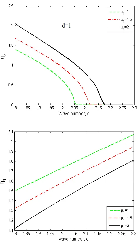
724 Figure3. Dispersion curves of the left-handed waveguide, for
p
=10GHz; F = 0.56, d=1, and for different values of
1.C. Modes of the Energy Flow in the Slab Waveguide
The energy flow in a stationary guided mode has the only component along the waveguide and it can be found as an integral of the pointing vector as [8]:
*
Re (8)
8
c
P E H
Where c denotes the speed of light.
2
(9) 8
i i
i cq
P
z
Where i = 1; 2; 3 denotes each of three layers of the structure. We thus obtain for the general case of non- symmetric cladding:
1 2 3
(10)
d d
d d
P
Pdz
P dz
P dz
In the symmetric waveguide, and in the normalized form:
2 2
2 2
2 2
2 2
1 1
2
2 2 2 2
0 0
(11)
tanh 2
tanh
Fω Fω
1 1
ω ω ω ω
N
P q d d d
[image:4.612.58.293.141.554.2]We give in what follows the evolution of the total energy flow of the LHM layer, we present and discuss the found modes in Fig.4.
Figure 4. Dependence of the normalized power of guided modes on the wave number q, the thickness d=1,
p= 10GHz; F = 0.56, andfor different values of
1.III. DISCUSSIONS
The first step of simulation is refers to the role of the cladding permeability, we plot the variation of the normalized frequency
p as a function of theInternational Journal of Emerging Technology and Advanced Engineering
Website: www.ijetae.com (ISSN 2250-2459,ISO 9001:2008 Certified Journal, Volume 4, Issue 5, May 2014)
725 When the wave number q varies from 1.8 to 2.3, the curves of the normalized frequency are presented between
0.238 and 0.254. Moreover, when
1is taken from 1 to 2, the zones of variation of the curves are changed and decrease from (0.245 and 0.254) to (0.238 and 0.249) as shown in Fig.2. Thus, one can suggest that the domain ofvariation becomes larger and larger when
1increases compared to the result obtained in [24]. The second step of simulations concerns symmetric waveguide and dispersion relation for a nonlinear layered structure, in the aim of giving different trends and emphasizing the new behaviors that can occur when we vary the permeability of the linear medium. Thus, according to the Eq.(12), we lead to the study of the dispersion mode curves as illustrated in Fig.3which is obtained for,
p = 10GHz, F = 0.56 andd = 1known as the normalized thickness. Figure3 presents new forms of TE dispersion modes for three values of the
permeability
1= 1; 1.5; 2, the curves of dispersion modes decrease from 2.1 to 0 as shown in Fig.3. But the domain of variation of that modes becomes significant from (0 and1.5) to (0 and 2.1) with the increase of
1. Those TEmodes become linear for
1 and increase from 1.1 to 2.1with
1as presented in Fig.3. Those results are different and new compared to that obtained in [24]. The third step of our analysis corresponds to the energy flow for the modes which is refereed to Eq. (11) and leading to Fig.4 ford = 1. The curves of energy observed are negatives for the
three values of
1when 1.8 < q < 2.3. Each of them increases, reaches to zero and begins to decrease as shown in Fig.4, so all the modes practically have similar trajectories. The most important fact is that the variation area of curves of energy becomes narrow from (-125 and-19) to (-40 and -21) when the values of
1 (namely,
1= 1; 1.5; 2) increase. One easily emphasizes that byincreasing the quantity
1the type of these modes changes as the wave number grows. Moreover, the total energy flowN
P carried by TE modes has a different behavior to that obtained in [24].
The modes are strongly dependent on the parameter
1, so more novel symmetric modes can be supported by the structure and there is a possibility that the energy flow can be controlled by changing the permeability of the linear medium as seen in Fig.4. In addition, we show behaviors and characteristics of the propagating waves which are different to that exhibited by waves propagating in conventional waveguides [25]. Consequently, the influence of cladding permeability on dispersion curves and energy flow leads to the significant change of the domain of existence of modes and the distribution of the waves guided along the left-handed slab.IV. CONCLUSIONS
In this paper, the effect of the permeability of the linear medium in a slab metamaterial waveguide with simultaneously negative permeability
2and negative permittivity
2 has been investigated. For this end, the dispersion relation in a system that consists of a metamaterial film surrounded by a linear cladding is derived, the guided dispersion characteristics of the slab waveguides are numerically investigated for various valuesof the permeability
1 . The energy flow is plotted againstthe wave number for different values of
1. Firstly, it hasbeen shown that the increase of
1increase the domain of the existence of the mode, so novel families of guided modes are found in a negative-index film. Secondly, the domain of existence of energy curves become narrow with1
. One of the important finding of this study is the appearance of the backward waves when the normalized energy flow depends on the dimensionless wave number qInternational Journal of Emerging Technology and Advanced Engineering
Website: www.ijetae.com (ISSN 2250-2459,ISO 9001:2008 Certified Journal, Volume 4, Issue 5, May 2014)
726 REFERENCES
[1] G. VESELAGO, ―THE ELECTRODYNAMICS OF
SUBSTANCES WITH SIMULTANEOUSLY NEGATIVE
VALUES OF
AND
,SOV.PHYS.USPEKHI, VOL.10,NO.4, PP.509–514.1968.
[2] J. B. Pendry,Negative refraction makes a perfect lens, Phys. Rev. Lett. 85, 3966, 2000.
[3] A. Alu, N. Engheta, “Achieving transparency with plasmonic and metamaterial coatings”, Phys. Rev. E, vol. 72, 016623, July 2005.
[4] J. B. Pendry, D. Schurig, D. R. Smith, “Controlling elec- tromagnetic fields”, Science , vol 312, pp. 1770-1780 , May 2006. [5] A. Alu, N. Engheta, Guided modes in a waveguide filled with a pair
of single- negative (SNG), negative (DNG), and-/or double-positive (DPS) layers, IEEE Trans. Microwave theory Technol. 52, 199, 2004.
[6] B.G. Onana Essama, J. Atangana, B. Mokhtari, N.Cherkaoui Eddeqaqi and T.C. Kofane, “Theoretical model for electromagnetic wave propagation in negative index material induced by cubic-quintic nonlinearities and third-order dispersion effects”, Opt. and Quant. Electron, vol. 45, pp. 292- 300, October 2013. [7] C.M. Soukoulis, S. Liden and M. Wegener, Negative refraction
Index at optical wavelengths. Science, 315, vol. 47-49. 2007. [8] M. Lapine, M. Gorkunov, and K. H. Ringhofer, Nonlinearity of a
metamaterial arising from diode insertions into resonan conductive elements. Phys. Rev. 2003, E 67: 065601.
[9] Shadrivov, I.V., Sukhorukov, A.A., Kivshar, and Y.S.: Guided modes in negative-refractive-index waveguides. Phys. Rev.E 67, 057602, 2003.
[10] Manenkov, A.B. Scattering Froman Abruptly Terminated Planar Metamaterial Waveguide. Opt. Quantum Electron. 53, 210-220, 2010.
[11] Manenkov, A. B. Abruptly terminated planar left-handed material waveguide. Opt. Quantum Electron. Vol. 45, pp. 529–541, 2013. [12] Manenkov, A.B. Proper and improper modes of the lefthanded
material waveguides. Opt. Quantum Electron. Vol. 44, pp.717-729, 2012.
[13] B. Mokhtari, N. Cherkaoui Eddeqaqi, J. Atangana, B. G.Onana Essama and T. C. Kofane, “Nonlinear dispersion equation and guided modes in a slab waveguide composed of negative- index medium”, Opt. and Quant. Electron, vol. 45, pp. 155–163, August 2013.
[14] A. Essadqui, J. Ben-Ali, D. Bria, B. Djafari-Rouhani and A. Nougaoui, Photonic band structure of 1D periodic composite system with left handed and right handed materials by green function approach, Progress In Electromagnetics Research B. 23, pp. 229-249, 2010.
[15] M.M.Shabat and H. M. Mousa,“The propagation of electromagnetic TE surface waves in magnetic super-lattices(LANS) film”, Proceedings of SPIE, vol. 6582, May 2007.
[16] H. M. Mousa, M. M. Shabat, H. Khalil and D. Jager, “Nonlinear surface waves along the boundary of magnetic superlattices(LANS)”, Proceedings of SPIE, vol. 5445, pp. 274-278, April 2004.
[17] J. B. Pendry, A. J. Holden, D. J. Robbins and W. J. Stewart, Magnetism from conductors and enhanced phenomena, IEEE Trans. Microw. Theory Tech. 47, 2075, 1999.
[18] Smith D R, Padilla W J, Vier D C, Nemat-Nasser S C and Schultz S, Phys. Rev. Lett. 84 4184, 2000.
[19] Pendry J B, Holden A J, Robbins D J and Stewart, W J. Phys.: Condens. Matter 10 4785. 1998.
[20] Pendry J B, Holden A J, Robbins D J and Stewart W J IEEE Trans. Microwave Theory Tech. 47 2075. 1999.
[21] K. Y. Kim, J. H. Lee, Y. K. Cho, and H. S. Tae, Electromagnetic wave propagation through doubly dispersive subwavelength metamaterial hole, Opt. Express 13, pp. 3653-3665 , 2005.
[22] L. F.Shen and Z. H. Wang, Guided modes in fiber with lefthanded materials, J. Opt. Soc. Am. A, vol 26, pp. 754-759 2009.
[23] S. Atakaramians, A. Argyros, S. C. Fleming, and B. T. Kuhlmey Hollow- core waveguides with uniaxial metamaterial cladding: modal equations and guidance conditions,J. Opt. Soc. Am. B, vol. 30, 851-867. 2013.
[24] S. A. Darmanyan, A. Kobaykov,D. Q. Chowdhury,“Non-linear guided waves in a negative-index slab waveguide”, physics Letters A, vol. 363, pp. 159-163, November 2007.