ON-DEMAND OFFLOADING COLLABORATION
FRAMEWORK BASED ON LTE NETWORK
VIRTUALISATION
Subah A. D. Albinali
School of Computing, Science and Engineering
College of Science and Technology the University of
Salford, Salford, UK
ii
Acknowledgements
Firstly, I would like to express my sincere gratitude to my supervisor Dr Omar Alani, for his continuous support of my PhD study and related research, for his patience, motivation, and immense knowledge. His guidance helped me during my research work and the writing of this thesis. I could not have imagined having a better supervisor and mentor for my PhD study.
iii
Abstract
iv
List of Abbreviations
1G First Generation 2G Second Generation 3G Third Generation
3GPP Third Generation Partnership Project 4G Fourth Generation
5G Fifth Generation AIPN All IP-Network AS Access Stratum
CAC Call Admission Control CAPEX Capital Expenditure
CDMA Code Division Multiple Access CN Core Network
D2D Device to Device eNB eNodeB
EPC Evolved Packet Core
E-UTRAN Evolved UMTS Terrestrial Radio Access Network FDMA Frequency Division Multiple Access
GERAN GSM EDGE Radio Access Network GGSN Gateway GPRS Support Node GPRS General Packet Radio Service
GSM Global System for Mobile Communication GSM-EFR GSM – Enhanced Full Rate
v IaaS Infrastructure as a Service
IMS IP Multimedia Subsystem
IMT International Mobile Telecommunication InP Infrastructure Provider
IoT Internet of Things
ITU International Telecommunication Union LBO Local Break Out
LIPA Local IP Access LTE Long Term Evolution M2M Machine to Machine
MAC Medium Access Control (layer) MME Mobile Management Entity MVNE Mobile Virtual Network Enabler MVNO Mobile Virtual Network Operator MVNP Mobile Virtual Network Provider NaaS Network as a Service
NAS Non-Access Stratum NRT Non-Real Time
OFDM Orthogonal Frequency Division Multiplexing OFDMA Orthogonal Frequency Division Multiple Access OPEX Operating Expenses
OTT Over the top operator
PCRF Policy and Charging Rules Function PDN Packet Data Network
vi QoE Quality of Experience
QoS Quality of Service RAN Radio Access Network RT Real Time
RWP Random Way Point
SAE System Architecture Evolution SDN Software Defined Network SIPTO Selective IP Traffic Offload SNR Signal to Noise Ratio SP Service Provider UE User Equipment
UMTS Universal Mobile Telecommunications Service UTRAN UMTS Terrestrial Radio Access Network VLAN Virtual Local Area Network
VN Virtual Network
VOIP Voice over Internet Protocol Wi-Fi Wireless Fidelity
vii
ON-DEMAND OFFLOADING
COLLABORATION FRAMEWORK BASED
ON LTE NETWORK VIRTUALISATION
Contents
Acknowledgements ... ii
Abstract ... iii
List of Abbreviations ... iv
Contents ... vii
List of figures ... xii
List of Tables ... xv
Chapter 1 ... 16
1 Introduction... 16
1.1 Background ... 16
1.2 Problem Statement ... 18
1.3 Motivation... 19
1.4 Objectives ... 20
1.5 Contributions ... 20
1.6 Research Methodology ... 22
1.7 Thesis Structure ... 24
1.8 Literature Review ... 25
viii
2 Underpinning Concepts ... 32
2.1 Introduction ... 32
2.2 LTE and LTE-Advanced ... 33
2.2.1 LTE Frame Structure ... 39
2.2.2 Bandwidths ... 41
2.2.3 Road to 5G ... 41
2.3 Virtualisation ... 42
2.3.1 Requirements for Wireless Virtualisation ... 44
2.3.2 Virtualisation in Mobile Communication ... 45
2.3.3 Business Model of Wireless Virtualisation ... 46
2.4 Offloading Techniques ... 49
2.4.1 Data Offloading Via Mobile Pathways ... 53
2.4.2 Homogeneous Deployments ... 54
2.4.3 Heterogeneous Deployments ... 55
2.5 Offloading (LBO) ... 56
2.5.1 Difference Between LIPA and SIPTO ... 57
2.5.2 Network Coupling ... 58
2.6 CAC Concepts ... 60
2.6.1 QoS Parameters ... 65
ix
2.6.3 Challenges in CAC Design ... 67
2.6.4 EPS Bearer QoS ... 70
Chapter 3 ... 74
3 Framework Fulfilments ... 74
3.1 Introduction ... 74
3.2 Derivation of The Average Number of Resource Blocks... 74
3.3 Channel Model of The LTE Simulator ... 75
3.4 Summary of The LTE Simulator ... 77
3.5 Proposed Framework ... 79
3.6 Symbology ... 83
3.7 Mathematical Model ... 84
3.8 Mobility Model ... 87
3.9 Poisson Process ... 89
3.9.1 Characteristics of the Poisson Process ... 89
3.9.2 Poisson Distribution ... 90
3.10 Poisson Distribution Simulator ... 93
3.11 Simulation and Emulation ... 94
Chapter 4 ... 95
4 Results and Discussions ... 95
x
4.1.1 Proposed CAC Algorithm ... 95
4.1.2 Numerical Results ... 96
4.1.3 Bandwidth Utilisation ... 99
4.2 Second Stage: Emulation EVE and Wireshark ... 101
4.2.1 Emulation preview... 101
4.2.2 Devices Topology Explanation: ... 103
4.2.3 TCP Retransmissions ... 104
4.2.4 TCP Duplicate/Selective Acknowledgments ... 106
4.3 The Emulation Scenarios ... 107
4.3.1 First Emulation Scenario ... 110
4.3.2 Second Emulation Scenario ... 115
4.3.3 Third Emulation Scenario ... 120
4.3.4 Fourth Emulation Scenario ... 123
4.3.5 Fifth Emulation Scenario ... 126
4.4 Evaluation of the proposed framework ... 128
Chapter 5 ... 130
5 Future Research Work and Conclusion ... 130
5.1 Future Research. ... 130
5.2 Conclusion ... 133
xi
APPENDIX A: MATLAB Code for LTE Simulator ... 145
APPENDIX B: MATLAB Code for PDS Simulator ... 149
APPENDIX C: Sample of Commands For Emulation Configuration ... 157
xii
List of figures
Figure 1 Voice And Data Traffic In Mobile Networks Between Q4 2011 And Q4
2016 [11] ... 18
Figure 2 Research Methodology Phases ... 23
Figure 3 A High-Level Mobile System Architecture In 2nd And 3rd Mobile Generation [38] ... 34
Figure 4. Evolution of Generations in Mobile Networks ... 35
Figure 5 Evolution Of The System Architecture From GSM And UMTS To LTE [44] ... 36
Figure 6 System Architecture Evolution [46] ... 38
Figure 7 LTE FDD Frame [49] ... 40
Figure 8 Business Models of Wireless Network Virtualisation [10] ... 48
Figure 9 Data Offloading Via Mobile Pathways [59] ... 53
Figure 10 New Call and Handover Call Process ... 62
Figure 11. End-to-End service delivery in LTE/LTE-Advanced architecture [44] 70 Figure 12 EPS QoS definitions and parameters [44] ... 71
Figure 13 High Level- Network Layout ... 82
Figure 14. Two Non–Overlapping Time Intervals of Duration 𝑡1 And 𝑡2, Respectively [79]. ... 91
xiii Figure 16 Blocking Probability of voice and data calls for the normal and
virtualised cases ... 98
Figure 16 Bandwidth Utilisation (non-virtualisation) ... 100
Figure 17 Bandwidth Utilisation. ... 100
Figure 18 Proposed Framework Flow Chart ... 102
Figure 19. TCP Retransmission [92] ... 105
Figure 20. TCP Duplicate/Selective Acknowledgments [92] ... 106
Figure 21: Emulation Diagram Created on EVE ... 109
Figure 22. Logic flowchart of the first scenario ... 110
Figure 23. Emulation Results for the First Scenario ... 111
Figure 24. TCP Retransmission Due to Network Congestion for the First Scenario ... 112
Figure 25 Normal RTD for Traffic that will pass to MNO1 in the First Scenario113 Figure 26. Significant Drops & Delay for the Excess Traffic for MNO1 in the First Scenario ... 114
Figure 27. Logic Flowchart of the Second Scenario ... 115
Figure 25. Traffic Analysis Towards MNO1 In the Second Scenario... 116
Figure 29. Traffic Analysis Towards MNO2 In the Second Scenario... 117
Figure 30. RTT shows congestion in MNO1 in the Second Scenario ... 118
Figure 31. TCP Capture of Live Traffic, MNO1 ... 119
xiv Figure 33. Logic Flowchart of the Third Scenario ... 121
Figure 34. Download Traffic carried over LBO. ... 122
Figure 35. Traffic Carried Over the LTE Core Network of MNO1 ... 122
Figure 39. All Traffic is carried over the LTE Core Network of MNO1 in the Fourth Scenario. ... 125
Figure 40. Logic Flowchart of the Fifth Scenario ... 126
xv
List of Tables
Table 1. Classification of Previously Reported Works Among Virtualisations and
Offloading Techniques ... 31
Table 2 LTE FDD Frame Boundaries [48] ... 40
Table 3 Bandwidth vs No. of subcarriers [49] ... 41
Table 4 Types of Network Coupling [60] ... 60
Table 5 Standardised QCI characteristics [78] ... 69
Table 6 Features of the LTE Simulator [16,76] ... 78
Table 7. Symbology ... 83
Table 8 PDS Numerical Results ... 97
Table 9. Emulation Scenarios ... 108
Table 10. Detailed Information about the Behaviour of the Packets in the First Scenario ... 115
16
Chapter 1
1
Introduction
1.1 Background
Recent technical reports show a tremendous increase in data traffic on mobile broadband networks [1], due to the growing numbers of users and the average data volume per user. Figure 1 illustrates such increase between the fourth quarters of 2011 and 2016; data traffic grew 55% and that the data traffic significantly overpasses voice traffic. In addition, worldwide mobile broadband users raised from 268 million in 2007 to 2.1 billion in 2013 [2]. This corresponds to an average yearly growth rate of 40%, making mobile broadband the most active market in Information and Communications Technology (ICT). Fulfilling this growing traffic poses an operational and cost challenge for mobile service providers considering that, (i) the spectrum dedicated to mobile communications is limited; in fact, nowadays is very difficult to obtain a new spectrum band since most have already been assigned (e.g. TV, satellite, Privet Mobile Radio) [3], and (ii) deploying a new network element such as a base station is difficult in some cases due to site issues, which create additional expense or even QoS degradation as a result of possible interference.
17 operators to guarantee coverage of up to 99.6% of the country’s population. In a similar
way, the United Kingdom, through the spectrum regulator known as Ofcom (Office of Communication), held an auction between the end of 2015 and the beginning of 2016 to make the new spectrum available for mobile broadband with a reserved price of between £2.5 million and £5 million per lot (10 MHz) for the 2.3 GHz spectrum, and £1 million for the 3.4 GHz lot (5 MHz) spectrum, leading to a total value of £50 million and £70 million. Yet more spectrum is required, together with the new technology needed to use the spectrum in a more efficient and effective way to cope with the tremendous increase in data [4].
18 which will require more efficient use of the spectrum, more aggressive frequency reuse and the collaboration of several enabling technologies [8].
[image:18.595.118.507.292.590.2]To this end, the wireless virtualisation technique has become a good alternative, attracting the attention of industry and academia as one of the critical enabling technologies towards the fifth generation (5G) [9]. In addition, the selective offloading strategy will deal with the demand for intensive bandwidth applications in a cost-effective manner, by bypassing the operator core network and lowering congestion [10].
Figure 1 Voice And Data Traffic In Mobile Networks Between Q4 2011 And Q4 2016 [11]
1.2 Problem Statement
19 to reduce both measures. Such a solution should necessarily rule out any physical expansion as a way to increase the capacity of the network and mainly devise real-time strategies to utilise the spectrum more efficiently. Some of these strategies might include (i) mobile network offload, either by employing underutilised resources from alternative operators or using other types of networks (e.g. Wi-Fi, WiMAX), or LTE network virtualisation, a technique that allows various virtual operators to use the same physical infrastructure simultaneously.
1.3 Motivation
Most of the previously reported research approaches and techniques in call admission control (CAC) have addressed the problem either degrading the quality of service to admit more calls or implementing costly solutions, such as installing additional base stations to increase capacity. In addition, typically a higher priority is given to handoff calls over new calls, which became a fundamental issue from a user perspective [12].
The spectrum dedicated to mobile communications has been licensed to different service providers or operators. Such spectrum remains to be somewhat limited, and it seems that the physical capacity required to fulfil the projected surge in mobile data traffic is higher than what the air interface can provide under the actual operating strategies.
20 QoS, which will require improving not only the spectral efficiency at the radio link level but the overall network efficiency. In a few words, it is necessary to find new methods and solutions to efficiently utilise the spectrum and manage such an increase in data traffic.
1.4 Objectives
General Objective
Propose a CAC algorithm to manage a collaborative strategy that combines network virtualisation and offloading to avoid network congestion and guarantee the quality of service.
Specific Objectives
- Build a mathematical model to determine the average number of resource blocks required for voice and data calls and the blocking probability of both types of calls.
- Evaluate the performance of the mathematical models by means of a simulation using MATLAB.
- Propose the CAC algorithm.
- Evaluate the performance of the proposed CAC algorithm by means of an emulation using open source applications, such as EVE, and Wireshark.
1.5 Contributions
21 alternatives for data offloading are LTE network virtualisation and Local Break Out (LBO) procedures implemented by the local operator. It is important to remark that any strategy to tackle this problem should be suitable for real-time functioning; this additional issue further complicates the solution of the problem.
In order to address the above-mentioned problem of traffic offloading, this work proposes an adaptive collaborative strategy among mobile network operators, by implementing the concept of Virtual Mobile Network Operator(VMNO) using a Virtual Network Enabler (VNE) element in conjunction with an LBO technique which is mainly the over the top service provider. To the best of our knowledge, most of the work carried out in this area has implemented a single approach.
The proposed strategy takes into consideration the possibility that one operator takes advantage of underutilised resources from other operators, as an opportunity to compensate a shortage in its resources and thus serve unbenefited traffic which may congest the core network (e.g. video stream and gaming), by diverting it to the LBO.
This should result in an essential reduction of the blocking and dropping rates, lead to better utilisation of the spectrum.
22 1.6 Research Methodology
The research methodology comprises the following phases:
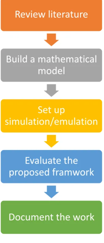
• Phase 1: Review the relevant literature
The literature review focused on topics related to this research, which include mobile networks standards (e.g. LTE and LTE-Advanced), elements of wireless virtualisation (Mobile Virtual Network Operator and Virtual Network Enabler (MVNO, VNE), Infrastructure Provider (InP), Service Provider (SP)), infrastructure and air-interface resources’ sharing, LBO, data offloading methods (LIPA, SIPTO, Wi-Fi offload) and its benefits, and CAC algorithms.
• Phase 2: Build a mathematical model
A mathematical model is built to describe the on-demand resource sharing (via virtualisation/offloading) for voice and data calls to operators. This model should include the calculation of average resource blocks required for voice and data calls, and the blocking probabilities of both types of calls using a Poisson distribution model. Also, a mobility model of users should be considered.
• Phase 3: Set up the simulation (first stage) and the emulation (second stage)
Regarding the first stage, MATLAB will be used to verify the proposed framework. This comprises an LTE simulator, to determine the average number of LTE Physical Resource Blocks required for voice and data calls, and a Poisson Distribution simulation, to determine the overall voice and data call blocking probabilities of the CAC algorithm which is a part of the framework for all operators in the air interface level.
23 The simulation will be used to verify the mathematical model through a numerical example, while the emulation will be used to validate the performance of the proposed framework.
• Phase 5: Document the work
The complete work is documented in a thesis structured in four chapters, as described below.
[image:23.595.225.401.320.729.2]Figure 2 illustrates how the phases are sequentially carried out.
Figure 2 Research Methodology Phases
Review literature
Build a mathematical
model
Set up
simulation/emulation
Evaluate the
proposed framwork
24 1.7 Thesis Structure
The rest of the thesis is organised as follows:
Chapter 2 gives the underpinning concepts related to the topic of the thesis. It starts describing the evolution of the generations in mobile networks, emphasising in LTE and LTE-Advanced. Then, it describes offloading techniques such as virtualisation and LBO, highlighting business models of Mobile Virtual Network Operators (MVNO), Virtual Network Enablers (VNE), Infrastructure Providers (InP) and Service Providers (SP). At last, it gives concepts related to the CAC, in particular, pros and cons of most of the CAC strategies and the challenges in CAC designs, including QoS parameters together with QoS of bearer in the evolved packet switch (EPS) network of the LTE and LTE-advanced system the End-to-End service delivery in LTE/LTE-Advanced architecture.
Chapter 3 describes the mathematical model within the proposed framework for on-demand sharing of air interface resources among mobile operators. This model constitutes the support of the applications that will be used to emulate real traffic situations in mobile networks in different scenarios. The average numbers of physical resource blocks (PRB) required for voice and data calls are computed using an LTE simulator. Then, the required PRBs are allocated both in the standard and virtualisation scenarios. In addition, a Poisson Distribution Simulator (PDS) is used to compute the voice and data calls blocking probabilities in the virtualisation scenario. At last, the Random Waypoint mobility model, which is used in the simulation, is explained.
25 second stage consisted of using commercial applications for emulating real traffic in the network for different scenarios, to validate the performance of the proposed framework utilising Offloading and Virtualisation.
Chapter 5 gives the overall conclusion of the thesis, highlighting all the main points and achievements. Finally, an outlook concerning future work is given.
1.8 Literature Review
Network virtualisation enables multiple network operators to share a common physical infrastructure (including core network, transport network and access network), in order to simultaneously reduce implementation costs and improve the overall performance. In recent years, substantial research efforts have focused on building virtual networks above the same physical infrastructure towards the future of the Internet [10]. Mobile network virtualisation is an essential technique which has recently attracted more research attention. For instance, Zaki [16] proposed an LTE virtualisation scheme, mainly focusing on addressing the benefits (in terms of capacity) that can be achieved by sharing the spectrum resources between different mobile network operators; more practical scenarios were investigated in [17].
26 solve the BIP with less computational overhead. All in all, the outcome shows the efficient use of the resources among the operators and preserves the sharing condition agreement. In [20] a collaborative spectrum-sharing framework was proposed with minimal modifications in the radio resource manager (RRM). Motivated by the virtualisation technology, a framework based on the 3GPP LTE is developed, in which the spectrum can be used by more than one operator in air interface level, taking into consideration the enhanced intercell interference cancellation (eICIC) feature, which is used as an isolation technique in the proposed virtual RMM. The network simulation parameters are based on the power and the radio propagation characteristics. The result verified the benefit of sharing compared to a standalone operator.
Similar work was applied in [21] to limit the mobile virtual networks (MVNs) embedded in the physical network, and to make use of the long- and short-term physical resource allocation leasing, with the formulation of the MVN admission control problem as a robust optimisation problem. Then the two-stage admission control has been converted to convex problems which have been solved effectively according to the simulation results and confirmed the usefulness of the proposed scheme.
27 resources to the mobile virtual network operators (MVNOs) to fulfil the dynamic needs of users, while satisfying the requirements of efficient resource allocation.
28 service providers (SPs) and the infrastructure providers (InPs). As a result, a framework has been developed which consists of pre-set parameters and an algorithm based on game theory, namely the Vickrey-Clarke-Groves (VCG) mechanism, to benefit from resources utilisation by modelling an auction game between the InPs and SPs, which are the MVNOs in this case. Zhang ,Zhao, ,Lopez, & Chen in [24] cited the importance of resource allocation in orthogonal frequency division multiple access (OFDMA) systems, which led to the efficient use of the energy because the focus was mainly placed in the power consumption and in maximising the data rate using a virtual resource allocation algorithm between the MNOs and MVNOs. The simulation shows that the performance in energy usage has been increased by 50 percent for the virtualisation approach, compared to the normal approach.
In [25] a new framework of wireless virtualisation is used to decouple the responsibilities of network entities. For instance, the network operator is responsible for resource allocation and the SPs for QoS. In addition, a VCG mechanism is used to verify that spectral efficiency can be reached, while the RRM and QoS provisioning can be decoupled from each other.
29 A few works considered the problem of resource allocation to VMNOs. For instance, an opportunistic sharing-based resource allocation scheme was proposed in [27], also driven by the virtualisation concept in wireless networks to overcome the shortage in spectrum by utilising it in more efficient and optimal manners. First, the problem of resource allocation has been formulated as an “NP-Hard integer program”. Then, two algorithms have been proposed: (i) a dynamic algorithm which mainly deals with resource sharing, by determining the most suitable process to be implemented to increase the revenue and resource utilisation rate, while reducing the cost of virtual networks and (ii) a heuristic algorithm to afford a simple but effective process which is easy to execute. At last, simulation results show the benefits of the proposed scheme. On the other hand, a bankruptcy game was proposed in [28] for dynamic wireless resource allocation among multiple operators. However, in this work, the users were not involved.
30 an alternative low-cost path [3]. Furthermore, solutions that focus on network capacity alone are not really tackling the root of the problem [30, 93].
On the other hand, the offloading strategy has also been used to decongest a network, by partially transferring the traffic to other types of networks, such as WiFi and WiMAX, among others. In [31] the authors proposed an algorithm for offloading LTE networks to WiFi networks, while in [32-34] show advances in the use of offloading to improve QoS in congested LTE networks. Now, as was previously mentioned, most of the reported works employ either virtualisation or offloading, i.e. they have been used separately.
Table 1 classifies some reported work among virtualisation or offloading. These works propose a collaborative strategy which combines virtualisation and offloading to improve QoS.
31
Table 1. Classification of Previously Reported Works Among Virtualisations and Offloading Techniques
Paper authors Virtualisation Offloading
C. Liang and F. R. Yu X
M. Kalil, A. Shami, and Y. Ye X
X. Wang, P. Krishnamurthy, and D. Tipper X
C. Liang and F. R. Yu X
G. Chochlidakis and V. Friderikos X
L. Gao, P. Li, Z. Pan, N. Liu, and X. You X
Y. Zhang, L. Zhao, D. Lopez-Perez, and K. Chen X
F. Fu and U. C. Kozat X
M. Yang, Y. Li, D. Jin, J. Yuan, L. Su, and L. Zeng X
K. Zhu and E. Hossain X
Y. Zaki, L. Zhao, C. Goerg, and A. Timm-Giel X
K. Samdanis, T. Taleb, and S. Schmid, X
Aiping Huang et al. X
Mojdeh Amani, et al. X
32
Chapter 2
2
Underpinning Concepts
2.1 Introduction
The bandwidth requirements in mobile networks have significantly increased in recent years. In the last few years, the usage time of smartphones has grown by 75 % and the usage time of tablets exhibits a similar trend [31].
In this context, mobile operators have been urged to offer higher transmission velocities, while simultaneously keeping the QoS to an increasing number of users. This necessarily involves increasing the capacity of the system to accept and maintain voice and data calls.
In addition, this situation has also motivated the research in the area, and the 3GPP has successively increased the capacity of the system developing the second (GSM+GPRS), third (WCDMA+HSDPA) and fourth (LTE and LTE Advanced) generation of mobile networks, and currently the fifth generation.
33 Now, the implementation of these strategies demands more complex algorithms to control the traffic flow in the network. This work proposes a CAC algorithm to manage the whole process on an LTE network.
2.2 LTE and LTE-Advanced
34 digital and micro-processing computing technologies. Historically, mobile technology has undertaken four evolution stages or generations.
Figure 3 A High-Level Mobile System Architecture In 2nd And 3rd Mobile Generation [38]
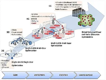
35 mobile networks. QoS provisioning in wireless networks is an arguing problem due to the scarceness of wireless resources (i.e. Bandwidth), and the mobility of users. Figure 4 illustrates the evolution of the different generations of mobile networks. In addition, Figure 5 illustrates the evolution of the system architecture from GSM and UMTS to LTE.
[image:35.595.121.463.353.612.2]In order to avoid network congestion and QoS degradation for the served users, a CAC mechanism became a necessity, since it can limit the access to the network resources based on the availability and simultaneously can provision the QoS of the service provided or will be provided to the end users [38]. According to the network layer architecture, different QoS parameters are involved in different layers.
Figure 4. Evolution of Generations in Mobile Networks
36 1 Gbps in the downlink and 500 Mbps in the uplink [7,40], and in the long run deliver peak data rates up to 3000 and 1500 Mbps respectively, using a total bandwidth of 100MHz that is made of five bandwidth components of 20MHz [40]. The specification also includes aims for the spectral efficiency in specific scenarios. LTE-Advanced is designed to be backwards compatible with LTE, i.e. an LTE mobile terminal can operate with a base station that is operating LTE-Advanced and vice-versa [41]. The introduction of Relay Stations (RS) and other techniques are the major differences between LTE and Advanced [42,43]. The use of OFDMA, MIMO and HARQ technologies allow LTE-Advanced to configure its bandwidth according to available frequencies dynamically and can support high mobility environments such as 350km/h in the case of high-speed rails [42].LTE-Advanced networks enable enormous flexibility in higher data rate provision and better QoS guarantee, but at the same time it is more complicated to gain precise quantitative insight into the capability of the system under different service provision scenarios, especially for practical LTE-Advanced network deployment, which requires professional capacity planning for improved user experience and reduced cost [43].
37 Along with improvements in the access technology for LTE, the overall system architecture of both the Radio-Access Network (RAN) and the Core Network (CN) was revisited. This also means that the split of functionality between the two network components was reconsidered. This work was known as the System Architecture Evolution (SAE), which resulted in a flat RAN architecture, while the Evolved Packet Core
(EPC) emerged as the new core network architecture [45].
The RAN handles radio related functions including radio-resource handling, retransmission protocols, scheduling and control of various multi-antenna schemes. The EPC provides a complete mobile-broadband network by means of functions such as authentication, charging functionality and setup of end-to-end connections [45]. Handling these functions separately, instead of integrating them into the RAN, is beneficial as it allows for several radio-access technologies to be served by the same core network. For example, the Radio Access Networks for 3G-HSPA and 4G-LTE could be served by the same core network [45].
Note that the Evolved Packet Core supports access to the packet-switched domain only, with no access to the circuit-switched domain. All voice and data accesses are done in the packet-switched domain only. The EPC consists of several types of nodes, which are described below.
38 The Serving Gateway (S-GW) is the user plane node connecting the EPC to the LTE RAN, which acts as the mobility anchor when the UEs move between eNodeBs in the LTE network, and even between other 3GPP technologies and the LTE network. This means that the S-GW will be the same even as the eNodeBs change due to the mobility of a terminal, i.e. the S-GW acts as an anchor for the mobility of the terminal.
The Packet Data Network Gateway (PDN Gateway, P-GW) connects the EPC to the internet. The P-GW handles allocation of the IP address for a specific terminal. The Policy and Charging Rules Function (PCRF) is responsible for QoS handling and charging, and the Home Subscriber Service node is the database containing subscriber information [45].
[image:38.595.123.512.454.726.2]The network architecture of the 4G, 3.5G and 3G systems along with femtocell deployments is shown in Figure 6.
39 The salient features of this evolution are [46]:
- System Architecture Evolution (SAE) is the core network architecture of the 3GPP’s LTE wireless communication standard
- SAE is the evolution of the GPRS Core Network for LTE, with some differences:
• Simplified architecture
• An all IP Network (AIPN)
• Support for higher throughput and lower latency radio access networks (RANs)
• Support for multiple heterogeneous access networks, including E-UTRA (LTE and LTE-Advanced air interface), 3GPP legacy systems (GERAN or UTRAN), also non-3GPP systems like WiMAX. The mobility of the terminal between above systems is supported.
2.2.1 LTE Frame Structure
40 The smallest unit of resources that are allocated to a user is known as a resource block (RB). In frequency the RB is 180 kHz wide, being either 12 x 15 kHz or 24 x 7.5 kHz subcarriers wide. In the time it is 1 slot long. Frequency units are expressed as several subcarriers or RBs. For example, as shown in Table 3, 1.4 MHz bandwidth in Downlink could be described as 6 RBs or 73 subcarriers wide [47].
The underlying data carrier for an LTE frame is the resource element (RE). which is the smallest part of the frame with 1 subcarrier x 1 symbol, and contains a single complex value representing data from a physical channel or signal (See Figure 7).
Table 2 LTE FDD Frame Boundaries [48]
Time Unit Value
Frame 10 ms
Half-frame 5 ms
Subframes 1 ms
Slot 0.5 ms
Symbol
(0.5 ms) / 7 OFDM symbols for normal Cyclic Prefix (0.5 ms) / 6 OFDM symbols for extended Cyclic Prefix Ts 1/ (15000 × 2048) sec » 32.6 ns
41 2.2.2 Bandwidths
The bandwidths of an LTE channel defined by the standard are 1.4, 3, 5, 10, 15, and 20 MHz. Table 3 shows how many subcarriers and resource blocks are there in each bandwidth for uplink and downlink.
Table 3 Bandwidth vs No. of subcarriers [49]
Frequency measures
Bandwidth Resource Blocks Subcarriers (downlink)
Subcarriers (uplink)
1.4 MHz 6 73 72
3 MHz 15 181 180
5 MHz 25 301 300
10 MHz 50 601 600
15 MHz 75 901 900
20 MHz 100 1201 1200
2.2.3 Road to 5G
3GPP continues to expand the LTE platform to new services while improving its efficiency to meet the increasing mobile broadband demand. To address the expanded connectivity needs of the future, 3GPP has started to work on the standardisation of the next generation mobile technology, also known as the fifth-generation technology or 5G [50].
42 Although there is not a definitive standard yet for a 5G technology, the groups working on the early trials have defined several key requirements going forward. Here are some of the most important ones [46]:
• 1Gbps to 10Gbps connections for peak data rates • 100Mbps cell edge data rate (mobile data speeds) • 1-millisecond end-to-end latency
• 1000x bandwidth per unit area
• 10-100x number of connected devices • 90% reduction in network energy usage • Full coverage.
Despite the advancements in technologies that enable high data rates over the wireless medium, the demand for data keeps increasing. Although more and more mobile spectrum is being allocated to operators to meet the customer’s insatiable
expectations of bandwidth, it keeps falling short. Offloading of data (for example, via Wi-Fi) provides a way to meet this demand. Mobile devices have built-in Wireless LAN transceivers, that can connect directly to the Wi-Fi access points when mobile access is unavailable or is congested, resulting in slow download speeds. Data offloading via Wi-Fi or via femtocells helps decongest data traffic. A drawback of offloading is that a mobile operator cannot monitor data traffic that does not go through its core network [46].
2.3 Virtualisation
43 Formerly, in the mid-1960s, the project IBM M44/44X was introduced, where the expression Virtual Machine (VM) was announced for the first time [51]. Virtualisation is the process of creating virtual layers of physical resources that duplicate the same physical characteristics. It is frequently deployed in the information technology field to convert the physical resources into some virtual parts, for instance, virtual memory, partitioning the hard disk, virtual machine.
Today, Server Virtualisation refers to the creation and maintenance of virtual machines. Since computers were very expensive in the past, at the beginning of this project the aim was creating several virtual machines out of one mainframe computer, to enable multi-task processes such as running applications and processes at the same time on one computer. Network virtualisation is the procedure of joining different virtual network resources into a Virtual Network. Individual virtual networks can contain operator specific protocols and architectures, which could be totally different from other coexisting virtual networks [52].
Moreover, network virtualisation also offers full flexible end-to-end control for the operators over their virtual networks [16]. Many research activities are focusing on the Future Internet architecture, have been launched around the world, such as (FP7 4WARD PROJECT) in Europe [53], VINI (Virtual Network Infrastructure) [54] in the U.S. and AKARI (Architecture Design Project for New Generation Network) [55].
44 In this work, a novel virtualisation collaborative structure will be adapted to allow mobile network operators to share the mobile spectrum and the infrastructure, such as the eNB hardware entity. The proposed structure targets the concepts of wireless virtualisation applied within the 3GPP LTE system, which represents one of the latest mobile communication systems technologies that are yet entering and still developing in the telecommunication market. Thus, such a technique will be used in an LTE network simulator with some changes, to cope with the proposed framework.
2.3.1 Requirements for Wireless Virtualisation
The requirements for carrying out wireless network virtualisation are the following [10]:
1) Isolation: Network virtualisation means the creation of individual virtual networks on top of shared physical network resources. These networks should behave independently of each other, i.e. they should be isolated. Security issues in one virtual network should not affect the other virtually created networks. A malfunctioning virtual network could end up consuming most of the resources of the underlying physical infrastructure of network elements. This should be prevented by having a limit of the resource consumption by individual virtual networks. In the wireless scenario, isolation would involve monitoring interference between the virtual networks, which makes isolation more complex in wireless networks compared to the wired counterparts.
45 networks should be programmable by their users; in case the users are service providers, they should be able to manage configuration and allocation of virtual networks, e.g., a routing table and virtual resource scheduling among others. Each logical isolated network partition (virtual network) should support the free deployment of control schemes or network architecture independent of other virtual or physical networks.
3) Coexistence: All virtual networks should be able to coexist on the same physical substrate network. Multiple virtual networks will have different QoS requirements, topology, security level, the behaviour of users etc.
4) Other requirements: Wireless virtualisation has some unique characteristics such as limited resource usage, signal interference, etc., that do not appear in wired networks. One of the biggest challenges is virtualisation of the wireless links because establishing a wireless link requires configuring parameters of the air channel between transmitter and receiver, such as the channel of operation, appropriate setting of transmitting power and receiver sensitivity, among others. In order to create two separate virtual networks that coexist on the same hardware, communication activities from one virtual network should not affect reception behaviour on the other virtual network in any form.
2.3.2 Virtualisation in Mobile Communication
46 consumption and the overall investment and operational costs [16]. Network virtualisation also gives the opportunity that small mobile operators can join the market and provide new services to their customers, by using existing physical infrastructure.
Furthermore, the idea of being able to share the frequency resources among multiple operators is a very interesting issue, which gives them full control to scale up/down the infrastructure and spectrum resources they use [16,52]. Thus, there are three main requirements to enable the virtualisation of mobile networks [19]:
1. Isolation between Mobile Network Operators (MNOs): Isolation is the capability of preventing the impact of one MNO on another, despite them sharing the same physical substrate. For instance, any modification in the traffic load or channel quality for any specific operator should not affect the others.
2. Customisation: MNOs have the ability to implement different custom scheduling policies, aiming to maximise profits and fulfil user requirements. Thus, different MNOs may have different services, QoS requirements, and business models. Radio resources are allocated to users based on scheduling policies, and every MNO have to be offered the flexibility to implement its own scheduling policy to achieve its objectives.
3. Efficient radio resource utilisation: Efficient use of the radio resources have to be maintained to the possible extent.
2.3.3 Business Model of Wireless Virtualisation
47 the constitution of the roles in the wireless network market and the main functions of these roles [10].
Generally, there are two logical roles following wireless network virtualisation, namely Mobile Network Operator (MNO) and Service Provider (SP) ([56-58]). All the infrastructure and radio resources of the physical substrate of the wireless network, including the licensed spectrum, radio access networks (RANs), backhaul, transmission networks (TNs), and core networks (CNs), are owned and operated by MNOs.
MNOs execute the virtualisation of the physical substrate networks into some virtual wireless network resources, which, for brevity are called virtual resources. SPs lease operate and program these virtual resources, in order to offer end-to-end services to end users. In some papers (e.g., [10]) the MNO becomes Infrastructure Providers (InP), which is only responsible for owning and leasing wireless network resources to SPs, who create and deploy virtual resources by themselves, based on the leased and allocated resources, to satisfy the requirements of end-to-end services.
The roles in the below business models are further decoupled into more specialised roles, including InP, a mobile virtual network provider (MVNP) and in some references such as in [10] refer to it as virtual network enabler (VNE), the mobile virtual network operator (MVNO) and SP. The functions of each of them are described in the following [10]:
48
• MVNP: Responsible for the creating process of the virtual resources and the leasing process of the network resources, because in some regulation cases the MVNP have the rights to own a licensed spectrum, so no need to request and utilise spectrum resources from the InP.
• MVNO: Operates and assigns the virtual resources to SPs. In some approaches, MVNOs performs the roles of both MVNOs and VNE. This model fits the emerging concept of the so-called providers of Anything-as-a-service (XaaS) [42] in cloud computing. InPs provide the Infrastructure-as-a-service (IaaS), while MVNOs provide networks-as-a-service (NaaS).
• SP: Concentrates on providing services to its subscribers based on the virtual resources provided by MVNOs.
Figure 8 Business Models of Wireless Network Virtualisation [10]
49 virtual resources are requested by SPs, managed by MVNOs, created by MVNP/VNE, and run on the physical resources owned by the InPs. Obviously, this four-level model can create more opportunities in the market and intuitively simplify the functions of each role. However, it requires more coordination mechanisms and interfaces, which may significantly increase the complexity and latency.
2.4 Offloading Techniques
Internet gaming, video and social media has become very popular on new devices such as tablets and smartphones, creating a surge of network data traffic. In addition, device to device connectivity commonly known to as machine to machine (M2M), is expected to give rise to a new set of applications that will require even more network capacity. Consequently, data traffic will grow significantly, thus urging operators to expend capacity, while data revenues are expected to only grow slowly creating a considerable gap accordingly. In this context, telecom operators need to continuously review their data traffic patterns and implement offloading mechanisms, which can help them manage their load and capacity more efficiently. Over-the-top (OTT) players are capturing a growing share of the value of the data that flows over the network. Combined with decreasing gain margins of telecommunication companies, requires that all this should be done in a more cost-efficient way. Some of the means that operators have to consider it in their network [59]:
50 resources by offloading data between licensed and unlicensed spectrum, as the number of connected devices continues to increase.
2) Controlling CAPEX. Operators are already investing heavily in upgrading their networks, to be able to meet the growing data needs of their consumers. However, their revenues do not increase as much as the increase in the data traffic. Hence, operators need to focus on core and access network investments only in those areas that offer the most active potential returns.
3) Backhaul Network Optimisation. Besides causing strain to the operator radio access networks, the growth in data traffic is also generating backhaul bottlenecks. Therefore, operators also need to design and implement an efficient backhaul system to transport the data from the access to the core network.
4) Transactional Load Management. It is crucial for operators to keep the signalling and transactional load to a minimum so that bandwidth optimised. With the increasing number of devices, this becomes a firm requirement.
51 Data traffic offload is an alternative that operators have at hand to reduce the traffic on their radio spectrum and lower the operating load on base stations. It also represents an opportunity for service providers to charge users to offload solutions such as small cells and help customers to reduce their usage costs by offloading data to alternate networks. In few words, a robust data offload solution can provide operators with flexibility to control data flow across the network based on traffic patterns, class of service and type of customers, thus achieving a better QoS.
There have been numerous research initiatives to explore potential solutions to efficiently utilise network resources, while simultaneously maintaining a high QoE for subscribers. Offloading is one specific family of solutions among the several possible solutions. The primary goal of offloading is to avoid transporting low priority traffic in costly networks, which may be done to avoid degrading the perceived QoE. The traffic that causes network congestion without creating any additional revenue should be targeted by mobile operators. Traffic redirection from parts of the network where congestion could occur to other low-cost parts of the network where capacity is available and less expensive is the basis of offloading. There are six different alternatives to offload data from the mobile network at either the access or the core network level. Each of them can co-exist, and the operator will have to determine which is the best based on multiple factors such as current infrastructure, customer usage patterns, associated costs, deployment and maintenance complexities and user density in a location. These alternatives are [59]:
1. Wi-Fi Hotspot
52 3. Integrated Femto / Wi-Fi
4. Direct Tunnel
5. Internet offload Gateway (IOGW)
6. M2M Gateway
In LTE systems, the idea behind traffic offloading is to free up the costly loaded paths, such as 3GPP Radio Access Network (RAN) and the Mobile Packet Core Network (MPCN), by redirecting part of the traffic to alternate, cost-effective paths. This could also be done by enabling the direct communication between nearby UEs via a D2D solution [51]. Several alternate offloading paths are standardised within 3GPP, such as the Interworking Wireless Local Area Network (I-WLAN) that integrates non-3GPP access (Wi-Fi) with the MPCN [52].
53 2.4.1 Data Offloading Via Mobile Pathways
Direct tunnelling is a method in 3G networks, in which data flows from the base station to the radio network controller GGSN and then directly to the Internet, thus avoiding the SGSN network element. This implies that service providers utilising this offloading solution would require much lesser SGSN nodes, which would result in reduced capital and operating expenses [59].
The Internet Offload gateway solution gives the possibility to selectively offload data traffic in a 3G network, between the Radio Network Controller and the SGSN. The non-profitable applications such as streaming media and surfing the internet are offloaded from the RNC to the internet bypass the core network, while the profitable ones are pass through the core network SGSN and GGSN [59].
54 Implementing this solution in the network, it would not be necessary for the operator to upgrade SGSN/GGSN in order to serve the important data growth because both are offloaded. However, the challenge of a restricted radio spectrum continues, since this solution is implemented in the core network [59].
Data may be offloaded via several pathways, within the mobile network itself (through same or different operators) or outside of the mobile network (for example, through Wi-Fi). Various data offloading pathways are illustrated in Figure 9.
2.4.2 Homogeneous Deployments
Multiple mobile operators co-exist in the same geographical area to provide services to their respective users, and they may have an unutilised spectrum which may be shared. Wireless virtualisation enables the dynamic sharing of physical infrastructure and air interface resources amongst the operators, based on user demand. In this way, the operating and capital expenses of the operators are reduced significantly. The users are unaware that they may be using the resources of other operators via virtualisation, so they are seamlessly connected to the LTE network [60].
Air interface virtualisation means the sharing of air interface resources among the mobile operators, for the benefit of their users. The LTE transmission frequencies are shared so that the user calls are not blocked or dropped as they move in and out of cells. Once the air interface resources are shared (obtainable via a Mobile Network Enabler), the call may use the Home Operator’s core network for reaching the Internet
55 Resources may also be shared through an LBO, in which both air interface and core network resources are obtained from a partner operator. In fact, the voice/data call is transferred completely to the partner operator. Therefore, the LBO is different from virtualisation since even the access to the internet is through another partner operator.
A network function virtualisation has been proposed as a promising way to allow multiple heterogeneous virtual networks (VNs) to coexist on a shared infrastructure. A major challenge in this respect is the VN embedding problem, which deals with the efficient mapping of virtual nodes and virtual links onto the substrate network resources. Since this problem is known to be NP-hard, research has been focused on designing heuristic-based algorithms which had a clear separation between the node mapping and the link mapping phases [61].
2.4.3 Heterogeneous Deployments
A mobile operator may operate via high power base stations (macro-cells) or low power base stations (femto or pico cells, also known as small cells), even with overlapping coverage areas. Calls of mobile users might be routed through the small cells rather than through the macro-cells if routing through the core network is not required. The former may be connected directly to the internet to offload the data [60].
56 for the high traffic and user density area , and it could very useful long-term strategy if it can manged and operated by the MNOs , but with some challenges in deployments that may affect the CAPEX and OPEX , on the other hand small cells in LTE technology can be deployed easier, which consider as one of the advantage in this technology [60].
2.5 Offloading (LBO)
As mentioned earlier, the rapid growth of mobile data traffic has posed challenges for mobile operators, who are looking for more cost-effective solutions to deliver mobile data without significantly compromising the QoS. To achieve CAPEX savings, 3GPP has offered some options to selectively offload certain mobile data to another path, without passing through Evolved Packet Core (EPC). Despite the fact that mobile operators have already deployed the LTE/LTE-Advanced networks that support high downlink/uplink peak rate as compared to legacy systems, the increasing network capacity still cannot keep up with the data traffic growth [67].
A large percentage of macro-mobile traffic initiates from local environments, such as home and enterprise networks, along with users that use bandwidth-intensive applications. Offloading selective mobile data traffic by low-cost fixed access networks and the Internet, thus avoiding the operator core network, is a promising solution [67,62].
57 solutions are currently offered by 3GPP’s System Architecture 2 (SA2) working group, namely LIPA (Local IP Access) and SIPTO (Selective IP to Offload) [67,62].
2.5.1 Difference Between LIPA and SIPTO
LIPA is mainly for end users to access their intranet locally through a local 3GPP access point such as indoor femtocells or picocells. In other words, whenever a user has his own internet access in his/her residential area by either a femtocell or a picocell, mobile devices can use LIPA to access other devices connected to the local network, such as a local computer. LIPA is subscription-based. A mobile device can use LIPA in its own network or in a visited network, subject to roaming agreements between mobile operators. It is up to the mobile operator to enable or disable Local IP Access for user subscriptions, per Closed Subscriber Group (CSG) for each LIPA Access Point Name (APN). The key benefits that mobile operators get from LIPA include [68]:
• Reduced network congestion for Local IP access
• Better quality of experience for services delivered through LIPA
• Improved revenues due to increased usage of operator networks for local access, which otherwise would have used WiFi, WLAN, etc.
58
• Reduced network congestion by offloading certain services
• Reduced CAPEX and OPEX with fewer backhaul requirements, which are typically leased by most operators.
• Improved Quality of Experience for subscribers, thus improved consumer satisfaction, leading to better revenues
2.5.2 Network Coupling
59 In a broader sense, network coupling is about the level of integration between two networks. The femto base station is another good example of tight coupling. In addition to the tight coupling at the core network level described above, a heterogeneous network may also create a tight coupling at different levels, for instance between two radio access networks, and allow one of them to take over the control of the other in the radio resource management control scheme.
An application example is the CDMA-LTE handover model, which is considered a tight coupling case at the radio link layer, offering the same level of fast handover performance [20].
In LTE-Advanced and beyond, this type of tight coupling can be extended to the air interface of the physical layer PHY and MAC layer, to allow the processes of joint radio resource management and traffic scheduling. In LTE networks, more tight-coupling issues in the context of the heterogeneous environment have been already implemented, such as the X2-link interface between a macro base (eNB) station and a femto base station (HeNodeB) [60].
Network coupling deployment is a difficult task and a hard business decision too, driven by the trade-offs of complexity, cost, security and performance. A mobile network operator may choose loose-coupling over tight-coupling, despite its potential higher performance; therefore, it all depends on the situation [60].
60 continue to advance in different markets and in different environments too, such as homes and enterprises [60].
Table 4 Types of Network Coupling [60]
Type of Network Coupling Exam. Design Characteristics Benefits and Complexity
No Coupling • Two networks operate
independently
• Mobile device connection manager coordinates wireless connectivity.
• No change to existing networks, suitable for roaming.
• The operator may perform offline billings
consolidation for a single bill.
Loose Coupling • Two networks share user credential and AAA. • Data traffic goes through
separate core networks.
• Common users/device credential for the two networks; potentially eliminate user intervention for WiFi access.
• Core network traffic offload to the internet.
Tight Coupling • User traffic goes through the mobile operator core network, (e.g., home femtocells connected through a Femto gateway)
• Opportunity for operators to offer value-added services.
• Opportunity to offer service continuity or even seamless handover. Very Tight Coupling • Two access networks are
directly interconnected. • Real-time radio resource
management across networks, (e.g., picocell connected through X2 interface)
• Opportunity to implement carrier aggregation and interference coordination. • Requires significant design
and implementation efforts.
2.6 CAC Concepts
61 (i) Accessibility: if a user makes a request for a call or data session, he/she gets
connected to the network.
(ii) Mobility: if a user is moving through the coverage while in the middle of a call or data session, he/she can keep the session even if a handover is necessary.
(iii) Retention: all sessions must only be released by the decision of the user.
In the third generation (3G) of mobile network technology, calls are known as RAB, with voice sessions being called CS RAB and data sessions PS RAB. Basically, there is two Key Performance Indicator (KPI) to measure the operation of the network: CALL DROPPED (CD) and CALL SETUP FAILURE (CF); the drop of both voice and data sessions are considered RAB DROP.
Fundamentally, the CAC constrains the access to the mobile network based on different criteria that primarily depend on the availability of the channel, in order to avoid, network congestion and service degradation, to fulfil the desired QoS parameters [12,64,65]. Figure 10 illustrates the concepts.
62 Home CellBS
UE
Neighbour Cell
BS
UE
Ne w C
all Pro
cess
Handov er Pro
cess
Figure 10 New Call and Handover Call Process
63 In heterogeneous networks, as a result of the collaboration between different radio access technologies (RATs) such as Wi-Fi and mobile networks, the seamless connection and global information mobility requirements need a type of collaboration CAC scheme, such that a call in one network has to be capable of moving and being handed over a different network technology pervasively; this is the so-called vertical handoff, and several related issues have to be considered [72].
A CAC approach based on signal quality parameters to trigger the handoff process will not perform satisfactorily if such parameters may be not measured reliably; furthermore, other system parameters have to be considered, such as the congestion level in the system in terms of channel availability. For instance, non-real time applications can be offered by WLANs in order to mitigate the congestion in mobile networks. All these factors will impact the distribution of the call holding time in both networks, which leads to increased dropping and blocking probabilities, especially in peak hours [72].
Generally, the data traffic varies along the day. For example, traffic reaches high levels during the daytime in the downtown area of a city, and alternatively high-level consumption at night in residential areas [57]. Moreover, such variation mainly depends on the geographic location and data dynamics, which is subject to the user movement and data consumption behaviour [57].
Therefore, this traffic difference among times and locations will lead to an imbalance usage, due to the static bandwidth and the dynamic demand by users.
64 which may affect the network performance in terms of highest allowed interference level and may lead to increases in CAPEX and OPEX. As mentioned earlier, single class CAC schemes are no longer appropriate to face growing requirements of data and multimedia services; multiple-service/class CAC schemes are more applicable, especially in the third-generation networks and beyond.
The design of multiple service/class CAC schemes is more challenging since some critical issues, such as service prioritisation, fairness, and resource sharing policy, have to be considered. Optimal CAC schemes as in [73] are always preferred, but not certainly achievable in a particularly realistic problem scenario.
Additionally, Cognitive Radio (CR) technology assists the progress of an intelligent and adaptive wireless communications system, which is basically aware of the radio frequency environment. So, the communication parameters (such as carrier frequency, bandwidth and transmission power) can be dynamically chosen, which lead to an efficient spectrum utilisation [74].
However, this technology faces many technical challenges, including protocol design, interference characterisation, environmental awareness, as well as the development of distributed algorithms, distributed measurement techniques, and quality of service (QoS) guarantees [75].
65 Similarly, [43] presents a study of mobile wireless networks which lease spectrum bands from another system. Both [41] and [43] show the benefits of spectrum renting in heterogeneous architectures and address the trade-offs between different CAC policies. These works consider a reserved band approach to mitigate the blocking and dropping probabilities
2.6.1 QoS Parameters
This section describes the QoS parameters that can be considered as admission criteria in CAC, to guarantee performance with acceptable KPI in a scenario with many users. This section and (2.6.2) cited from [58,66]
1. Signal Quality: This parameter is used to guarantee acceptable interference levels in wireless networks. In few words, more congestion will result in a network with the more degraded signal quality for the users in terms of the interference level. Therefore, the possible admission criteria could be the following:
(i) Number of users in a cell (ii) Interference level
(iii)Transmitted power from the base station
(iv)Received power from the base station or the user terminal
The call is granted admission if and only if it can keep a minimum signal quality level without interfering with existing calls; this applies to new and handoff calls.
66 reserving a portion of the bandwidth for handover calls use only. The corresponding admission criteria may be:
(i) Nnumber of users per class in a multiple-class system. (ii) Approximate handover failure probability.
(iii)Availability of resources.
3. Packet-Level Parameters: When a wireless network provides packet-oriented services, overloading can cause an unacceptable level of packet delay or end-to-end system delay (delay jitter) by the system service bearer. Therefore, CAC should be deployed to manipulate the packet level threshold to warrant the required QoS parameters (packet delay, delay jitter, and throughput). Under this circumstance, the admission criteria may be:
(i) Number of users.
(ii) Availability of resources.
(iii)Estimation of packet-level QoS parameters.
4. Transmitting Rate: CAC schemes are utilised in wireless networks through data services that intend to guarantee a minimum transmission rate. Nevertheless, it is more complex in wireless networks due to user mobility, limited bandwidth, channel characteristic and channel noise.
2.6.2 Other QoS Strategies
67 offered to calls already active and may lead to a higher dropping rate in calls. Hence, CAC can be used to increase the network revenue function based on the potential profit and the consequences of admitting new calls. In this situation, the admission criteria can be:
(i) Number of users.
(ii) Estimate of the probability of QoS deterioration.
2- Prioritise some services or classes: One of the purposes of a CAC scheme may be assigned a higher priority to some services or classes.
3- Fair Resource Sharing: Establish equality between different users in the same class and between users of different classes, based on criteria such as channel condition and mobility characteristics. A CAC can be employed to accept or reject users based on the allocated resources, such that no user class controls the network resources.
2.6.3 Challenges in CAC Design
68 The aim of CAC is to help service provider to ensure that their customers are satisfied with appropriate QoS parameters while utilising the limited network resources in a more efficient way.
The quality of service class identifiers (QCI) shown in Table 5 is the most important parameters used to measure the QoS of a bearer in an LTE network. With respect to Table5, the following quantities can be defined [73]:
(i) Resource type: Guaranteed bit rate (GBR) or non-guaranteed bit rate (Non-GBR).
(ii) Packet loss rate: Indication for the part of packets that are lost as a result of errors in the transmission and reception processes.
(iii)Packet delay budget: Indication, with 98% assurance, for the delay that a packet experiences between the mobile and the packet data network (PDN) gateway. (iv)QCI priority level helps in the scheduling process.
As aforementioned, the GBR and non-GBR are the two types of bit rate bearers involved in Evolved Packet System (EPS). The GBR value is predefined permanently and linked with an EPS bearer by an admission control function executed at eNB level; else, an EPS bearer is considered as a Non-GBR [73].
![Figure 1 Voice And Data Traffic In Mobile Networks Between Q4 2011 And Q4 2016 [11]](https://thumb-us.123doks.com/thumbv2/123dok_us/8663813.871026/18.595.118.507.292.590/figure-voice-data-traffic-mobile-networks-q-q.webp)

![Figure 3 A High-Level Mobile System Architecture In 2nd And 3rd Mobile Generation [38]](https://thumb-us.123doks.com/thumbv2/123dok_us/8663813.871026/34.595.140.480.148.458/figure-high-level-mobile-architecture-nd-mobile-generation.webp)
![Figure 6 System Architecture Evolution [46]](https://thumb-us.123doks.com/thumbv2/123dok_us/8663813.871026/38.595.123.512.454.726/figure-system-architecture-evolution.webp)
![Figure 11. End-to-End service delivery in LTE/LTE-Advanced architecture [44]](https://thumb-us.123doks.com/thumbv2/123dok_us/8663813.871026/70.595.127.514.74.313/figure-end-end-service-delivery-lte-advanced-architecture.webp)