5th International Scientific and Business Conference—Future Engineering 2019 ISBN: 978-1-60595-632-9
Rehabilitation Robot for Upper Limbs
Andrzej Michnik
1, Jakub Wołoszyn
1, Mariusz Sobiech
1and Grzegorz Nowak
1ABSTRACT
In an aging society, injuries and diseases are the causes of the dysfunction of motor structures. Recovering the required efficiency of the motor structures, in addition to immediate medical help, usually requires a tedious and long-term rehabilitation process. In the classic approach, rehabilitation is conducted and carried out by a rehabilitator, whose work consists in selecting appropriate types of exercises to limit dysfunction and then physical work, consisting in performing the appropriate exercises with a rehabilitated limb. This paper presents the process of creating a rehabilitation robot at the Institute of Technology and Medical Equipment in Zabrze, which, in the future, can relieve the physiotherapist from performing physical work, while providing a diagnostic tool, thanks to data obtained from robot sensors. An objective and rapid estimation of the patient's limb abilities can be valuable information that can be used to assess the progress of rehabilitation. Information about the progress of rehabilitation along with an attractive training scenario, in the form of 3D games, can be an important factor motivating the patient to long-term and laborious rehabilitation exercises.
Keywords: rehabilitation, upper limb, robot, control system, force feedback
INTRODUCTION
Physiotherapy is a major part of the treatment process of motor dysfunctions of the limbs as a result of past diseases or injuries. The large number of patients in ________________
1Łukasiewicz Research Network – Institute of Medical Technology and Equipment ITAM,
need of rehabilitation is due to several different reasons. The main reasons include the fact that the society is aging and civilization diseases caused by unhealthy lifestyles and road traffic accidents. Impairment of the locomotor system hinders the performance of vital functions, causes pain, and makes the patients unable to work [1,2].
Physiotherapeutic training implemented sufficiently fast following the occurrence of the dysfunction is a prerequisite for the recovery of lost ability as much as possible. Limited access to rehabilitation often results in long waiting times. As a consequence, subsequent procedures are less effective than might be expected [3].
[image:2.612.171.427.471.643.2]Rehabilitation is likely to become more accessible due to the use of robotic devices supporting this process. Physiotherapists currently use devices that relieve them from the burden of performing exhausting exercises with the patient. Owing to the costs, popular devices mainly perform simple movements in single joints. Examples of simple devices for the rehabilitation of single joints include the following: for the fingers and wrist joint—Kinetec 8080, elbow joint—Artromot-E, and shoulder joint—Kinetec Centura Shoulder CPM [4]. There are also devices for spatial training. The main instance of such a device is the robot called ARMin, developed at the Zurich Polytechnic. In its first version, six degrees of freedom of movement were applied, four of which were driven while two were passive. ARMin had a kinematic scheme allowing it to work from the shoulder joint to the forearm. In the next version, two degrees of freedom of movement for the forearm and wrist were added [5]. The design of the ARMin robot, Version III, was commercialized under the name of Armeo Power by HOCOMA and is currently a reference example of a commercial rehabilitation robot as shown in Fig. 1. The robot makes it possible to perform spatial rehabilitation training with feedback.
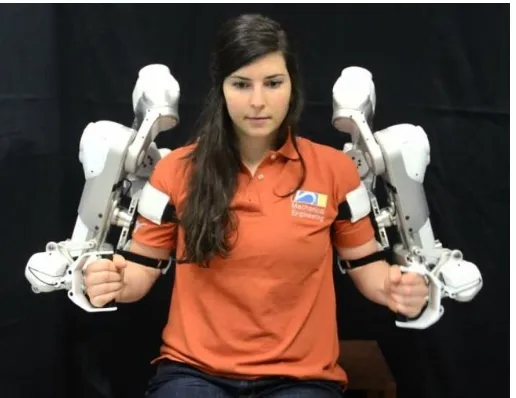
Figure 2. A photo of the rehabilitation robot Harmony.
Other interesting designs of fixed exoskeleton rehabilitation robots include Harmony, an example of a robot developed at the University of Texas at Austin, USA. The robot is unique in that shoulder anatomy is mapped by the kinematic scheme of the robot arm and exercises can be performed simultaneously with two limbs [6] as shown in the photo in Fig. 2.
The physiotherapist’s tool of the future that will make their work easier and will improve access to rehabilitation for the patients will be a robot that could repeat with the patient set patterns reflecting spatial movements without the need to involve the physiotherapist’s muscles [7,8]. Depending on the type of training, a physiotherapist’s task would boil down to choosing a workout scenario and programming the essential parameters of the workout performed by the robot. In addition to relieving the physiotherapist from physical work and achieving a high repeatability of set parameters, sensor elements of the robot also make it possible to obtain precise information on flexion angles in the joints and the patient’s muscle strength. Hence, the robot can also become a diagnostic tool to facilitate the evaluation of the patient’s condition and rehabilitation progress, which is likely to increase motivation for further exercise. Another important factor that can increase the motivation for strenuous and exhausting exercises may be to offer the patient rehabilitation in the form of games in which the robot will play the role of human-machine interface with feedback.
Technomex in Gliwice, within the framework of the competition InnoNeuroPharm announced by NCBiR. However, with regard to the ARM-200 robot, due to the current lack of patent applications, detailed information will not be provided. The work will focus mainly on the components of the control system of the rehabilitation robot.
KEY ASSUMPTIONS OF THE CONTROL SYSTEM
The key assumption of the design of the ARM-100 rehabilitation robot was that the robot should take the form of a mechatronic exoskeleton operating one of the upper limbs. The exoskeleton was to be connected to the patient’s seat, where the patient would perform exercises in a sitting position. An assumption was also made that the mechanical design and control system of the robot would allow the exoskeleton to be reconfigured to either the right or left upper limb. Another assumption was that the patient could have both passive and active training.
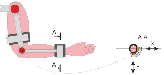
Figure 3. The general idea behind the control of a rehabilitation robot; presentation of the connection between the drive and the correct pressure sensor.
THE CONTROL SYSTEM OF THE ROBOT
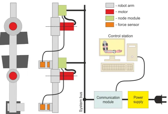
The control system of the rehabilitation robot consists of three main elements: modules of measurement and performance nodes, the communication module, and a PC with control software, Fig. 4. In the presented diagram, the node modules are placed on the robot’s arm elements. This reduces the number of wires running through the moving parts of the robot’s arm between the sensors and the node module.
Figure 4. The structure of the robot control system.
A PC with control software makes it possible to remember the trajectory of the movement of the rehabilitated limb in the form of a training program as well as makes it possible to replay the remembered training program by adequately controlling the measurement and performance nodes. During the training session, the system operator starts the trajectory recording in the program. After the training trajectory input is complete, the operator initiates the trajectory replay. The program plays the role of a multi-channel movement recorder. Each of the remembered trajectories can be saved on a disk to compare rehabilitation progress later on.
The communication module is also used for disconnecting the power supply to the robot drives in an emergency. Emergency power supply disconnection results in immediate activation of the brakes in robot drives that may potentially cause hazard. The brakes are also activated in the event of power failure. The disconnection of the power supply for the brakes is operated by an independent control line. As a result, robot drives will definitely be stopped as soon as the emergency button is pressed.
THE CONSTRUCTION OF THE NODE
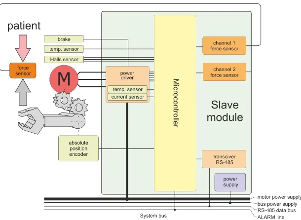
calculates the relative rotational position and rotational velocity of the drive based on changes in signals from Hall sensors. The core of the Slave module in the ARM-100 robot is the 8-bit microcontroller PIC18F4431, dedicated to BLDC motors. Two force measurement channels, motor current measurement, and temperature sensors are connected to the microcontroller’s analog-to-digital converter. The Slave module design diagram shown in Figure 5 presents the components of a node, where the letter M stands for a three-phase BLDC motor which works with the brake: a temperature sensor and Hall sensors on the one hand and the gear behind which the absolute position sensor is placed on the other. The figure also demonstrates the schematically placed force sensor which is mounted between the robot arm and the patient. This makes it possible to use modes in which the robot arm follows the patient’s arm based on pressure to achieve zero force. The information from the force sensor can also be used to stop the workout and thus protect the patient’s limb from excessive load in the event of, e.g., spasmodic muscle contraction. It is also possible to use the force sensor to set the load by adjusting the appropriate insensitivity threshold. After the threshold is passed, the controller will enable the movement.
[image:7.612.145.450.427.650.2]During system startup or after starting the zero position procedure, the Slave module reads the absolute position from the external angular position sensor in the form of a magnetic sensor working with the magnet. The absolute position sensor is another element developed for the design. Figure 6 shows a photograph of the control system node, i.e. the Slave module, together with a connected BLDC motor, force sensor, and absolute angular position sensor.
Figure 6. A photo of the elements of the measurement and performance node.
BLDC drives with MAXON MOTOR planetary gearheads were used to develop the ARM-100 robot. In the current development of the ARM-200 robot, one of the major changes is the replacement of planetary gearheads with harmonic gears, which are more compact in size, with virtually no backlash and no additional bearing required. Moreover, 8-bit microcontrollers were replaced with 32-bit microcontrollers with an ARM Cortex-M4 core. 32-bit controllers make it possible to perform a much larger number of operations between successive cycles of queries in the control system.
Figure 7. A photo of the test stand for testing single-engine operation control algorithms.
BLDC motor with gear
Slave module
Force sensor
Absolute position sensor
motor drive arm
force sensor
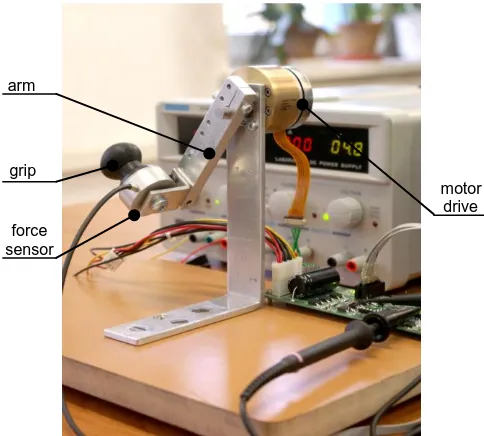
[image:8.612.176.418.442.660.2]After assembling the electronics of the Slave module, a simple test stand was constructed to enable verification of the controller’s operation, performance tests, and the improvement of drive control algorithms in different modes of operation. An important element of the work on the test stand was also the initial selection of coefficients for regulators stabilizing velocity and position. The stand shown in Fig. 7 consisted of a single Slave module working with a BLDC motor and a force sensor on the arm. A grip was mounted on the other side of the force sensor to allow hand contact with the sensor.
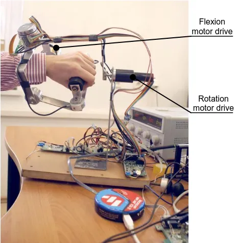
[image:9.612.205.435.345.583.2]A second test stand, demonstrated in Fig. 8, was then built to test the end part of the robot’s arm with three degrees of freedom. The second test stand made it possible to test the operation of the control system with two connected robot nodes. In this configuration, the Slave modules provide each other with amplified signals from force sensors F1 and F2, which makes it possible to bend and rotate the hand with the sum and difference of the signals from the force sensors. Figure 9 shows a diagram of how the nodes operate in such a case. An additional third motor located at the top performs independent abduction and adduction movements in the wrist joint.
Figure 8. A photo of the test stand for testing three-engine operation control algorithms.
The built-in software of the Slave modules is the same for all nodes; however, the required parameters can be configured individually using the PC application. In this way, the gain of the measuring channel and the insensitivity zone can be set in order to limit the influence of the hysteresis of the sensor system in
Rotation motor drive
movement tracking modes based on the indications of force sensors. Individual configuration of PI regulators and other parameters, due to differences in the motors, gears, and sensors used, is also required. The configuration parameters are transferred during the initialization of the workout after the connection with the PC control program is made.
Figure 9. A diagram of pairing nodes with the hand grip as an example.
Each node is capable of operation in force-support mode or position stabilization mode. The force-support mode is mainly used for programming the rehabilitation trajectory, but it also allows for active training by adjusting the insensitivity threshold of the force measurement path. The position stabilization mode enables passive training, in which the robot replays the previously saved rehabilitation movement by moving the robot arm to the next previously saved points. Sending a new position frequently enough results in a smooth movement that maps the movement entered by the physiotherapist.
A simplified operating algorithm of the measurement and performance module in the force support mode is shown in Fig. 10. Two PI regulators are the core elements of this system. The first regulator stabilizes the rotation velocity of the drive, and the velocity is directly proportional to the applied force. The second regulator is intended to stabilize the position. As a consequence, the range of movement in a given node is limited. The direction of force is switched by the position regulator between two states: the position change to the angular position MAX or to MIN. However, a given element is displaced only if appropriate force is applied which exceeds the set insensitivity threshold of the force measurement path. The displacement velocity is directly proportional to the applied force above the insensitivity threshold—subject to the permitted range of motion. The position controller automatically reduces the velocity to zero when the moving element reaches the limits of the movement range of a given part.
Rotation motor drive
Figure 10. A simplified block diagram of the force-support algorithm.
STRUCTURE OF THE COMMUNICATION MODULE
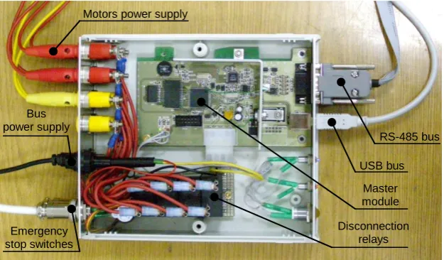
The communication module (Master module) mediates in communication between the computer application, which controls the workout and the performance modules. The communication module is responsible for receiving the data packet from the computer application via a USB interface, then for distributing and sending sequentially the commands contained in it to individual Slave modules using the RS-485 bus, waiting for the answers of the Slave modules, and then sending the collected information to the control application via the USB interface. During the experiments, a significant impact of the access time of about 20 ms to the USB bus was observed. In order to limit the impact of this delay, commands and answers sent via the USB interface were grouped into single packets as demonstrated in Fig. 11. In the current ARM-200 robot design, the Ethernet 100 MB interface, which is free from the above-mentioned disadvantage, is used to communicate with the computer.
An additional function of the communication module is to disconnect the power supply from the robot drives when one of the two emergency stop switches is pressed by means of relays built into the communication module shown in Fig. 12.
Figure 12. A photo of the elements of the communication module.
COMPUTER APPLICATION
The main element of the control system of the robot is a training control application installed on a PC. The application makes it possible to configure the parameters of performance nodes, present the status of individual performance nodes, and give commands. In the basic scenario, the movement trajectory learning mode can be started by pressing the RECORD button. After entering the trajectory, the trajectory playback mode can be started with the set number of repetitions by pressing the PLAY button. The trajectory is replayed back and forth from the first to the last sample and then from the last to the first sample. As shown in Fig. 13, the application window makes it possible to monitor the parameters of the robot. This is a test application used to evaluate the operating parameters of the device.
RS-485 bus
USB bus Motors power supply
Bus power supply
Emergency stop switches
Disconnection relays
Figure 13. The main window of the application controlling the ARM-100 rehabilitation robot.
[image:13.612.152.445.357.629.2]In order to better evaluate the robot’s performance, a visualization of the robot’s components has also been developed (Fig. 14) by means of the OpenGL standard function [9,10], with the use of appropriately modified basic objects, such as a sphere, a cuboid, and a cylinder. The obtained information on rotations in individual physical nodes of the robot was used to animate the virtual robot in the application window in real time. The computer application of the current design of the ARM-200 robot will be equipped with simple 3D games to make the rehabilitation process more attractive, and, in addition, the games will be an important factor stimulating the regeneration of the patient’s nervous system.
A PROTOTYPE OF THE ARM-100 ROBOT
[image:14.612.140.454.403.654.2]The end result of the project was the construction of a prototype of a rehabilitation robot with seven degrees of freedom (Fig. 15), containing the control system that has been described above. The design is based on drives from the Swiss company MAXON MOTOR, consisting of BLDC motors and planetary or cylindrical gearheads. In the current design of the ARM-200 robot, planetary gearheads have been replaced with harmonic gears in several nodes, which make it possible to significantly reduce the size of drive elements as well as to eliminate additional bearings and backlash in gears.
SUMMARY
This work presents the stages of building a prototype of the ARM-100 rehabilitation robot from the vantage point of the control system, without focusing on the mechanical challenges of the design. The aim of the paper is to present the path from a simple idea behind a single node of a control system to a working prototype. Current work on the new design of the ARM-200 robot shows new hardware capabilities that enable the completion of tasks with greater accuracy, capabilities, and safety. An example can be power transistors, which at present are in the same housing, have ten times lower conductivity resistance. This translates into a significant reduction in the power lost in drive controllers. Another instance of a technological leap forward between the prototype of the ARM-100 robot and the present version is the available microcontrollers. The previously used 8-bit microcontroller processed data with a 10 MHz clock, while the currently selected microcontroller is a 32-bit device with a 240 MHz clock. Moreover, the new microcontroller has a number of internal structures to carry out hardware tasks in order to relieve the processor. The paper is also aimed to inspire other engineers to build low-level solutions, such as drive controllers or 3D visualization using simple OpenGL functions.
REFERENCES
1. Zambaty, A., ed. 2002. Kinezyterapia. Kraków: Wydawnictwo “Kasper”.
2. Kwolek, A., M. Drużbicki, and G. Przysada. 2004. “Zasady rehabilitacji szpitalnej chorych po udarze mózgu”, Postępy Rehabilitacji, 18(3): 7-9.
3. Najwyższa Izba Kontroli. 2018. Realizacja Zadań Narodowego Funduszu Zdrowia w 2017 Roku, Nr ewid. 156/2018/P/18/055/KZD.
4. Blauth, W. 1992. The CPM therapy with motorized exercise devices. München: Urban & Vogel.
5. Nef, T. and R. Riener. 2012. “Three-dimensional multi-degree-of-freedom arm therapy robot (ARMin)”, in Neurorehabilitation technology, V. Dietz, T. Nef, W.Z. Rymer, eds.. London: Springer; pp. 141–57.
6. Bongsu, K. and D. Ashish. 2017. “An upper-body rehabilitation exoskeleton Harmony with an anatomical shoulder mechanism: Design, modeling, control, and performance evaluation”,
The International Journal of Robotics Research, 36(4): 414–435.
7. Michnik, R., J. Jurkojć, Z. Rak, A. Mężyk, Z. Paszenda, W. Rycerski, J. Janota, and J. Brandt. 2008. “Kinematic analysis of complex therapeutic movements of the upper limb”,
Information Technologies in Biomedicine, 47: 551-558.
8. Michnik, R., J. Jurkojć, Z. Rak, A. Mężyk, Z. Paszenda, W. Rycerski, J. Janota, and J. Brandt. 2008. “Analiza kinematyki ruchów kończyny górnej podczas wykonywania ćwiczeń rehabilitacyjnych metodą PNF”, Modelowanie Inżynierskie, 36: 243-248.
9. Matulewski, J. 2006. C++Builder 2006 - 222 gotowe rozwiązania. Gliwice: Wyd. Helion, pp. 391-423.