Test Case Generation using UML State Diagram and
OCL Expression
Md Azaharuddin Ali
School Of Computer science VIT University Tamil Nadu-
600048, India
Khasim Shaik
School Of Computer science VIT University Tamil Nadu-
600048, India
Shreyansh Kumar
School Of Computer science VIT University Tamil Nadu-
600048, India
ABSTRACT
Manual software testing is both an expensive and time consuming activity, requires proper planning and resource. This paper proposed a method to automate the process of test case generation. This proposed technique reduces time and increase the reliability of the software testing processes. The main criteria of software testing are to generate test cases. This methodology consist of transforming the state diagram (UML) into finite state machine (DFA / NDFA) where each node represent state and the arrow connecting the states represent transition. The nodes store state information and arrows maintain trigger information which is necessary for state transition. Mined information and pre- and post- condition of the states are used to build test case. The proposed technique attains sufficient test coverage without increasing the number of test cases. It also achieves much important coverage like transition coverage, transition pair coverage, and provides state coverage
General Terms
Software Testing, UML, State Diagram, Test Case
Keywords
DFA, NDFA, Sequence diagram graph (SDG), OCL
1.
INTRODUCTION
Software testing includes executing software on a group of test cases and verifies the particular results with the expected results. The important task of software testing is to assure the quality of software product. Existing test sequence generation methods are costly, time consuming and also with less testing coverage. This may cause the following critical issues: a) The project budget may be increase, particularly in the
large software systems. Testing may take about 50% of total budget [1].
b) It may cause a delay of developing software system phase. c) Some test cases may not be covered (less coverage) and tested properly, In future which may causes to many known flaws.
A well tested software package will be checked by the client before acceptance. However, in object-oriented environment the designing and implementation of software is complicated because it has to deal with important object-oriented concept like polymorphism, inheritance, encapsulation, dynamic binding etc. This makes software testing complicated and more chance to error-prone.
In software engineering a test case is a set of criteria or variable under that a tester will validate whether the software system or an application is working properly or not. Usually
software developers may not have enough time to create test case after coding phase to test their code. This problem can be solved by generating test case before the coding phase. It will help the developers to test their software after the end of coding [2]. Generation of test cases using UML model are one of the most significant method. This method has many advantages it can cover the issues raised by object-oriented paradigm. However, test case generation from UML model is not an easy task it is the most challenging task. Because test case needs so many parameters like input values, pre- and post-condition of the input values, and the expected output. Several researchers propose to way out of this problem, but that increase the complexity of test case generation effort. In this paper the proposed technique is use to generate test case automatically using UML models. UML State diagram is used as a source for test case generation. Generated test suits achieve much important coverage like transition coverage, state coverage, transition pair coverage etc. State diagram alone is not sufficient to generate test data, some more different parameters that is input values, pre- and post-condition of the test case, and expected output is needed. For that purpose UML model like use case diagram is also used here.
2.
RELATED WORKS
Several research attempts have been proposed for test case generation under various circumstances, mainly scenario based, path oriented, model based, goal oriented approaches. Scenario-based test case based on concurrent approach with concurrence coverage criteria. Path-oriented testing based on static and also dynamic flow of the software. Static path testing is based on symbolic execution, and dynamic path testing done by evaluation of running time of executing program. Model based technique is deal with different UML models such as state-chart, sequence diagram, object diagram, activity etc. Goal oriented technique identify test case which covers a selected goal such as a branch or statement. Many researches have been going to generate test case based on the specifications.
a) Monalisa [3] have proposed a technique which used UML sequence diagram to generate test case. They transformed the UML case diagram to sequence diagram graph (SDG), and they generate test case based on two coverage criterion.
b) Novada Haji Ali and Sufian Idris [4] they design an assessment system for UML diagrams. They developed a tool named UCDA that can produce list of comments on a UML diagram.
8 system and user, that information is used to generate
automatic test suit. In this process use cases textual description is converted into activity diagrams.
d) Ranjit Swain, Prafulla Kumar Behara at al [6] they used function minimization technique and construct test case automatically from UML state chart diagrams. First the diagram is prepared then the diagram is traversed using DFS to select associated predicates. After that initial dataset is guess and conditional predicates are transformed to generate test cases.
e) Bertolino and Basanieri [1] [7] they proposed a technique which describe how to generate test cases manually using Use Case and Interaction diagrams. The main objective of this technique is to check the pre-tested software modules are interact correctly at integration testing or not. In sequence diagram the different component interacts with each other through message passing. This message information is used with category partition method (CPM) to generate test case manually.
f) A novel approach proposed by M.Lettrari and J. Klose [9]. They focus on real time system only.
g) P.Tonella and Potrich [10] they used reverse engineering technique on UML sequence diagram to generate test case.
Now UML becomes most widely used language. For model based test case generation several researchers are focused on different UML models like sequence diagrams, use-case diagrams, state-chart diagrams, class diagram etc.
3.
PROPOSED APPROACH
The propose approach is to transform a given state diagram into a finite state machine (FSM). Each node in FSM stores necessary information for test case generation. The important feature for test case generation are stored in node of FSM, these important feature collected from use case diagram including pre and post- conditions are expressed using Object Constrained language (OCL). Finally based on different coverage criteria FSM is traversed to generate the suitable test case.
3.1
OCL expression for pre and
post-conditions
Object Constrained Language (OCL) is a declarative language for describing rules that apply to Unified Modeling Language (UML). It was developed at IBM and presently part of the UML standard [13]. It is very advantageous for UML model because of following reasons.
OCL provides expressions that are not ambiguous like natural language.
OCL has higher abstraction level than any other OOPL. For this reason generating code from OCL reduce error rate. In addition, this allows reuse of the captured business rules on all supported target platforms.
The most important benefit of using OCL is that its gives a precise specification of the systems requirements, and also helps us to gain a better and more complete understanding of the system
An example of ATM is given below to show, how to determine pre and post condition of ATM system using use case diagram.
3.2
Pre- and Post- Condition of Use Case
Pre-condition:- Before creation of use case diagrams it is the necessary state that must be present to the system.
Post-condition:- It is lists of possible states that may be exist just after a use case has finished.
Example 1.
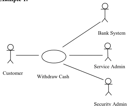
[image:2.595.320.542.107.292.2]Fig 1: Use Case diagram of money withdraw from a bank account using ATM
Pre-conditions of Cash Withdraw
The customer with valid ATM card.
Context ATM :: withdraw (amount : Integer ): Boolean Pre: bank.atm.valid=true;
Active network connectivity with the Bank System must exist.
Context ATM
Pre: bank.network.alive=true;
There must be sufficient cash in the account to withdraw. Context ATM :: withdraw(amount : Integer) : Boolean Pre: customer.account.balance >=0 and
account.balance>= amount.
Post-conditions of Cash Withdraw
If the customer enters the wrong PIN three times, the card should be retained.
Context ATM :: withdraw(amount:Integer):Boolean Post: numberOfPinTrials = numberOfPinTrials@pre + 1 and
if uPin = customer.card.pin and numberOfPinTrials <= 3
then pinAccepted and
result = PinResult::true else
not pinAccepted
numberOfPinTrials = numberOfPinTrials+ 1 result = PinResult::false
endif
If the customer enters correct PIN number and the customer's account balance is greater or equal to the requested amount, then only the customer can able to withdraw the requested amount and the same amount must be deduced from the customer’s account.
Context ATM::withdraw(amount:Integer) : Boolean Pre: pinAccepted
Customer
Withdraw Cash
Bank System
Service Admin
Post: if (amount <= customer.account.balance) then customer.account.balance =
customer.account.balance@pre - amount and
result = true else
customer.account.balance = customer.account.balance@pre and
result = false endif
The ATM card will be returned back to the customer if the customer wants to withdraw excess money.
Context ATM::withdraw(amount:Integer) : Boolean Pre: pinAccepted and withdraw=true
Post: if (withdraw=true) then customerAccountClose and
result= AtmCardReturn::true else if(numberOfPinTrials>3) then customerAccountClose and
result= AtmCardReturn::true endif
3.3
Transformation of State diagram to
FSM
UML state diagram provide a way to model the behavior of the system by analyzing how the state of the system changes in response to input data.
Every software system has something that is called its state. Software state consists of the current value of the entire variable in program at any given moment in time. In the case of object oriented system the state of the system is stored within the object in the system, and each object has its own state which is stored in the object’s variables (class fields). The essence of running a computer program is changing the software from one state to another. Finite state machine (FSM) used to model the software system conceptually. FSM has fixed number of states and the system is always any one of the fixed number of states when it is running. As computation progress the FSM transition from one state to another. Each state machine can receive input and it possibly produces output during state transition upon entering a state, upon leaving a state or even within a state. FSM is two type Deterministic and Non-deterministic. In practice of writing software model, the effect non-determinism are trying to be reduced. Since non-deterministic program could produce different result each time, they run with same input. Therefore deterministic approach is considered in this process.
Definition of DFSM:
A deterministic finite automata consist of 5-tuple M=Q,, , q0, F
Where
Q Is finite set of all states i.e. set of all FSM nodes defining various conditions of operation scheme; each node signifies an event.
Is finite set of input symbol, transition is happened for these inputs.
Transition function, it describe from where to where states are moving for a particular input.
q0 Operation begins from this state, means it is initial state.
F Operations will terminate to this state. It may be single or set of node.
We define operation scheme (OpScm) as 4 tuple, OpScm: <SId, BeginState, TransitionSet, NextState> SId A unique id for each operation scheme. BeginState Is a starting point of scheme.
TransitionSet It include set of all events that happens in an operation scheme.
NextState System enters to this states after completion of an operation scheme. It may happen that a DFSM has a single begin state but multiple end state which depends on various operation scheme.
Four tuple is used to represent an event in a “TransitionSet”. aEvent :<tr, S, R, G>
tr Value or name of the trigger for which transition occur. S Current node/state which sends trigger.
R Next node/state where transition occur form current node. G It is a guard condition used to decide which event will
occur next.
Example2.
`
[image:3.595.318.537.343.688.2]
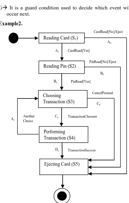
Fig 2: State diagram of one session ATM system.
CardRead[No]/Eject
Reading Card (S1)
Reading Pin (S2)
Choosing Transaction (S3)
Performing Transaction (S4)
Ejecting Card (S5)
CardRead[Yes]
PinRead[No]/Eject
CancelPressed
/Eject
PinRead[Yes]
TransactionChoosen
TransactionSuccess Another
Choice
Dy
Cy
Cn
Ac
Ay
By
Bn
10
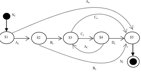
[image:4.595.356.541.71.266.2]Fig 3: DFSM for the state diagram of fig 2.
Table 1. Is defined by following State Transition Table
Ay An By Bn Cy Cn Dy Ac
S1 S2 S3
S2 S3 S5
S3 S4 S5
S4 S5 S3
S5
List of possible operation scheme from DFSM
OpSCm1: Nf S1S5N1 OpScm2: Nf S1S2S5Nl OpScm3: Nf S1S2S3S5Nl
OpScm4: Nf S1S2S3S4S3 S5Nl OpScm5: Nf S1S2S3S4S5Nl
3.4
Test Case Generation
A state diagram provides a way to model the behavior of the system by analyzing how the state of the system changes in response to input data. So, the test set is essential to detect faults during the state of an object is changes from one to another. It is necessary to cover all possible combination of paths from start to end node of DFSM to ensure maximum coverage.
Algorithm TestCaseGeneration
Input: DFSM Graph Output: TestSet T
Notation: Nf, Nc, Nn, Nl are the first, current, next and last node respectively.
Testcase Γ= {Pr, s, r, G, Po} Where
Pr Pre-condition of node/state.
s Set of input value/ trigger for senderNode.
r Set of output value/ resultant node after transition. G Set of guard condition for transition.
Po Post-condition of node/state.
The event Ec corresponding to current node Nc is Ec= (tr, S, R, G).
Steps:
Take all paths = 1, 2,….., n from the start to end node in DFSM.
FOR each path i do Nc← Nf
Γi ← ɸ //Initially testcase for the operation //scheme OpScmi will be empty. Nc ← Nn //Move to next node of OpScmi WHILE (Nc ≠ Nl)
Ec= (tr, S, R, G) //The event of Nc.
IF G = ɸ THEN
Γ= {Pr, s, r, Po} Γi =Γi U Γ ENDIF
IF G ≠ ɸ THEN
Γ= {Pr, s, r, G, Po} Γi =Γi U Γ
ENDIF
Nc ← Nn+1 //Go to next node of Nn //on the path i. Γ =ΓU Γi
ENDWHILE
Determine the final output r and Po from the operation scheme OpScmi stored in Nl. Γ= {Pr, s, r, G, Po}
T← T U Γ //Add the test case to test set ENDFOR
RETURN (T) STOP.
TestSetGeneration algorithm starts by considering all paths in DFSM from start to end node. A path essentially corresponds to an operation scheme. The test case for all possible paths from start to end node are considered and integrate them one by one to generate final TestSet T.
The main strategy of testing is to detect certain type of fault that can be called as fault model [12]. Our testing technique is based on following fault model.
Transition fault: Generally in a state diagram the state
of an object is changed from one to another when some certain conditions are true. In this state transition there may be several faults like, incorrect response or state change to an input, correct input pass to a wrong state, incorrect input pass to a right state, input passed with improper or incorrect condition or guard value.Scheme fault: Each operation scheme represents to all
possible sequence of transition path in state diagram. For a particular operation scheme, transition of state may not adopt a particular route because of inappropriate guard statement, or abnormal termination etc.4.
EXPERIMENTAL RESULT
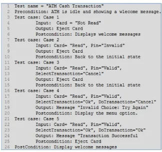
To prove the effectiveness of the generated test cases, we took the example of ATM Cash Transaction problem. Visual Paradigm v. 8.0 is used to produce UML diagram, and exported in XML format. We have developed a Java based parser which reads a UML state diagram in XML format and convert it into DFSM Graph. The node of DFSM graph is defined using template defined inside java program. The OCL 2.0 syntax is used to represent pre or post conditions and Breadth-first traversing algorithm is used to traverse the all possible paths of DFSM.
The experimental approach is built on Java programming language in Linux OS and run the program in Intel machine. The above experiment is consider on 5 different path of the DFSM (in Fig. 3) and produce 5 test cases as shown in Fig. 4.
5.
CONCLUSIONS
It has been proved that different UML models are effectively used to generate test cases. This paper suggests a technique to achieve test cases based on UML state diagram. This approach will help software developer and tester to start the testing process quickly in the software development life cycle.
S1 S2 S3 S4 S5
Ay By
Cy
Dy
Bn
AC
Cn
Nf
The prerequisite information like pre and post-condition is collected from use case diagram and expressed in terms of Object Constrained Language (OCL 2.0) [11][13]. The best part of this approach it does not require any alteration in the UML models to generate test cases. DFSM is basically a graph based methodology and the proposed algorithm enumerate all possible path to generate test case. In worst case with n nodes the time complexity of the proposed algorithm is O (n2) which is significantly less and this suggests that this technique is capable enough to handle big enterprise project efficiently. The major impact of this paper is use case and state diagram and this approach could be extended for Nested State diagram and other UML diagrams for further research.
6.
REFERENCES
[1] Myers G. “The Art of Software Testing” 2nd ed. Year 2004: John Wiley
[2] Beck K. “Test-Driven Development by Example” Year-2003: Addison- Wesley. 220.
[3] Monalisa Sarma, Debasish Kundu and Rajib Mall, “Automatic Test Case Generation from UML Sequence Diagrams”, 15th International Conference on Advance Computing and Communication, 2007, pp. 196-201.
[4] Novada Haji Ali, Zarina Shukur and Sufian Idris, “A
Design of an Assessment System for UML Class Diagram”, 5th International Conference on computational Science and Applications, 2007, pp. 539-544.
[5] J. Hartmann, M. Vieira, H. Foster, and A. Ruder, A UML-based Approach to System Testing, Journal of Innovations System Software Engineering, Vol. 1, PP. 12-24, 2005.
[6] Ranajita Swain, Vikas Panthi, Prafulla Kumar Behera,Durga Prasad Mohapatra, “Automatic Test case Generation From UML State Chart Diagram”, International Journal of Computer Application, Vol 42, March 2012,
[7] A. Bertolino, and F. Basanieri, A practical approach to UML-based derivation of integration tests, in Proceedings of the Fourth International Software Quality Week Europe, Brussels, Belgium, 2000.
[8] T.J. Ostrand, and M.J. Balcer, The category-partition method for specifying and generating fuctional tests, Communications of the ACM 31 (6)
[9] M. Lettrari M. and J. Klose, Scenario-Based Monitoring and Testing of Real Time UML Models, in the Proceedings of UML 2001, Springer Verlag, pp. 312-328. (1998).
[10] P. Tonella, and Potrich, A. Reverse Engineering of the Interaction Diagrams from C++ Code, in the Proceedings of IEEE International Conference on Software Maintenance (2003) 159–168.
[11] Object Constraint Language 2.0 is available from the main website of Object Mangement Group (http://www.omg.org/).
[12] M. Esser and P.Struss,"Fault-model-based Test Generation for Embedded Software" International Journal of Computer Application, 2007.
[13] Absolute Astronomy Object Constraint Language, Encyclopedia
[image:5.595.136.460.436.739.2](http://www.absoluteastronomy.com/topics/Object_Cons traint_Language)