Analysis of Performance Parameters for Microstrip
Antenna using Novel Hybridization Method
Mithila R. Ghuge
M.E (EXTC Dept) Matoshri College of Engineering and Research
Center,Nasik Maharastra, India.
A.P.Khedkar
A.P(IT Dept) Matoshri College of Engineering and Research
Center,Nasik Maharastra, India.
Prathmesh U. Indulkar
M.E(EXTC Dept) Vidyalankar Institute of Technology,Wadala,Mumbai
Maharstra,India
ABSTRACT
In the recent era of wireless communication, Microstrip antenna (MSA) is hot research topic attracting attentions of many researchers. But MSAs have few foremost drawbacks viz narrow impedance Axial Ratio Bandwidth (A.R.BW), low gain and power handling capability. To overcome these drawbacks, novel hybridization method is proposed. A hybridization method includes array method, parasitic patch on superstrate cover and multi stacking instead of the conventional superstrate cover. To achieve the high efficiency, air is used as dielectric medium between feed patch and ground plane as well as between superstrate and feed patch. Due to low cost, availability and ease of fabrication FR4 material is used as superstrate. Proposed system is implemented using FR4 and the results of simulation clearly indicate parametric variations for the various hybrid methods.
General Terms
Wireless communication, Microwave application
Keywords
Array method, gain enhancement, hybridization, microstrip antenna, superstrate cover
1.
INTRODUCTION
In wireless communication for long coverage of wireless devices there is need for an antenna which works on the high frequency range. For the need of wireless devices MSAs are perfect choice because of their operation in the high frequency range from 1GHz to 300GHz. Before two and half decades, Deschamps from USA and also Gutton and Bassinot from France delivered the concept of MSA (MSA) [1]. Later Munson developed MSA which use as low profile flush mounted antenna on rocket and missiles proved that MSA was practical concept for use in many antenna system problems and from his valuable invention new era of antenna industry come into picture [1]. The previous research study on MSA reveals the limitation of narrow BW and low gain there by indicating further scope of research [1]. At frequency range of 5.725 GHz to 5.875 GHz and 2.4 GHz to 2.5 GHz which is license free ISM (Industrial Scientific and Medical) band frequencies, communication system requires compact, high performance and low cost wireless equipment. This is one of the reasons for getting importance to MSA [1]. ISM radio band of frequencies are used for the entire antenna design, simulation and testing. Performance parameters such as gain, directivity, return loss, antenna efficiency and radiating efficiency get affected for each modified antenna structures. This wok studied the effect of these parameters in detail.
The proposed hybridization methods are designed, implemented and the results of simulation are presented in section IV below.
2.
LITERATURE SURVEY
Researchers studied the MSAs considering different parameters such as gain, BW, radiation pattern etc. They also consider methods to improve these parameters such as change in shape of patch antenna, change in dielectric substrate, using superstrate, removal of substrate, and combination of different methods. For enhancement of gain of MSAs array method is effectively used by H. Wang et.al designed 2 x 2 MSA line feed U-slot rectangular array these antenna gave gain of 11.5 dBi and 18% BW [2]. Chao Sun, Jiu-sheng Li proposed planar microstrip antenna for WLAN application at 5GHz WLAN band without any modification in structure presented by H. Wang et.al gave gain of 19.72 dBi [2][3]. M.T.Ali et. al developed 2 x 2 MPA with air substrate at 5.8 GHz operating frequency and they found enhancement of gain up to 38.21% [4]. Horng-Dean Chen, Chow-Yen-Desmond Sim, Jun-Yi Wu, and Tsung-Wen Chiu modified MSA by developing two novel array antenna i.e 3 x 2 and 3 x 3 array antennas for WiMAX application and these antenna structure gave gain of 17 dBi and cover up to 3.3 GHz to 3.8 GHz WiMAX band operating frequency [5]. Tommy Reynalda et al designed 4 x 4 array antenna using dielectric constant of 2.5. This structure is inspired by [4] having difference in number of array and dielectric substrate. Later it compare with single patch antenna having dielectric constant of 2.5. Researcher observed that modified structure has gain 16.02 dB and 150 MHz BW, while single patch antenna has gain 6.10 dB and 50 MHz BW [6]. This proved that array structure enhances the gain of the MSAs.
antenna tends to increase gain of MSAs was scrutinize by these researchers.
Furthermore change in dielectric substrate also influences the gain of the MSA. Sudhipta chattopadyay et.al devises rectangular MPA with part of dielectric substrate as PTFE and rest is air and enhanced gain of the MSA [11]. Dongying Li et al considered structure in which low meta-material used as substrate at 9.45 GHz frequency range and observed 80% gain enhancement [12].Using superstrate in MSAs also contributes in gain enhancement Avinash R. Vaidya et.al deliberate the superstrate height on MSA. They observed that high gain is achieved by placing superstrate layer at above integral multiple of half wavelength above the ground plane [13]. Siew bee yeap and Zhi Ning Chen improved gain of MSA by partial removing the substrate and observed that gain enhanced up to 2.4 dB to 2.7 dB by this method [14].
Different gain enhancement method is studied by the many researchers some authors also combine two methods like V. Priyashman et.al analyzed the performance of elliptical shaped antenna by using superstrate with random slots at 5.8GHz frequency they also showed that gain and BW influenced by the superstrate structure [15]. In this author combine change in shape along with the superstrate cover. Kaushik Mandal and Partha Prtim Sarkar designed U-shaped patch antenna with two equal arms using PTFE (poly tetra fluro ethylene) substrate. Just under the U shaped patch introduced inverted U-shaped slot on circular shaped ground plane. They achieved 4.1 dBi gain and BW enhancement of 86.76%. Structural modification in MSAs effect the gain of the MSAs these proved by the researches [16].
3.
DESIGN OF ANTENNA
Before presenting the Antenna design details, the brief introduction of performance parameters is given. Further in the design process of antenna, it is prerequisite to do analysis of antenna in terms of length, width, εr, thickness etc. This
analysis in terms of mathematical expression is presented below.
3.1
Performance Parameter of Antenna
3.1.1. Antenna Gain
Antenna gain defined by the intensity of an antenna in a given direction to the intensity that would be produced by a hypothetical ideal antenna that radiates equally in all directions or isotropically and has no losses. Since the radiation intensity from a lossless isotropic antenna equals the power into the antenna divided by a solid angle of 4π steradians, we can write the following equation:
1) ...( ... ... ... P ower Input Antenna Intensity Radiation 4Π Gain
...(2) ... ... ... ... ... ... P φ θ, U 4Π Gainin
where U(θ,ϕ) is radiation intensity and Pin is antenna input
power.
3.1.2. Return Loss
It is the measure of how well devices or lines are matched and it is given by
...
3 P P log 10 dB R r i 10 L where RL is return loss, Pi is incident power and Pr is reflected
power.In other words, it is logarithmic ratio that compares the power reflected by the antenna to the power that fed into the antenna from transmission line.
) 4 ....( ... ... ... ... ... 1 SWR SWR Log 20
RL 10
where SWR is Standing Wave Ratio.
3.1.3. Directivity
It describes how much power is transmitted in direction of peak radiation to that of an isotropic source. Directivity is the ability of antenna to focus energy in the particular direction when transmitting or to receive energy better from a particular direction when receiving. i.e ability of antenna to receive signals from one direction while rejecting interference signal from other direction. Directivity is defined as
1.6 ...
5 Log 10 6 . 6 W 2 . 0 D 2 / 1 r 10 where W is width of the antenna and εr is relative dielectric
constant.
3.1.4. Radiating Efficiency
It is the ratio of radiated power to the input power of antenna. It is between 0 and 1 and measures in terms of percentage (%) for example 0.1=10%.It is define as
) 6 ...( ... ... ... ... ... ... ... ... P P e i r r
where er is radiating efficiency. Radiating efficiency is less
than 100% due to conductor loss, dielectric loss and surface wave power.
3.1.5. Antenna Efficiency
It is the radiation efficiency multiplied by the impedance mismatch of the antenna. Total antenna efficiency is always less than the radiating efficiency.
3.2
Physical Design Parameter of Antenna
3.2.1. Choice of Substrate
While designing MSA substrate selection is as crucial as the design itself. Radiating properties of MSAs is depends on the substrate used in antenna design. Dielectric constant, thickness, stiffness as well as loss tangent are important factors for substrate selection. To encourage fringing and hence radiation dielectric constant should be as low as possible. A use of thicker substrate can increase the impedance bandwidth but it incurs a loss in accuracy. For the approximation in the analysis a thin substrate is use in most MSA models. In our project we have selected air as the dielectric material having dielectric constant as 1.
3.2.2. Element Length
The length of the patch should be slightly less than half the dielectric wavelength since the actual patch is ‘longer’ due to the fringing fields. The length of the patch is given as ) 7 ...( ... ... ... ... ... ... ε 2f C L eff 0 eff
Where Leff represented effective length of antenna, f0 represent
effective dielectric constant and ΔL represent the line extension at the ends given by Hammerstad as
0.8 ...(8) h W 0.258 ε 0.264 h W 0.3 ε 0.412h ΔL eff eff Where W is the width of the feed patch and h is the height of the feed patch from the ground plane. The effective dielectric constant ε may be static or frequency dependent value which is given as follow.
[image:3.595.328.540.77.225.2] [image:3.595.58.279.112.159.2] [image:3.595.323.536.319.425.2] [image:3.595.68.268.530.601.2]
9 ... ... ... ... W h 12 1 2 1 2 1 2 1 r r eff Where εr represented relative dielectric constant of material
Therefore length of the feed patch can be calculated as
10 ... ... ... ... ... ... ... L L L eff 3.2.3. Element Width
For an efficient radiator, width is given by
11 .... ... ... ... ... ... ... 2 1 f 2 C W r 0 4. STRUCTURES OF ANTENNA
4.1. Design of Reference MSA Antenna
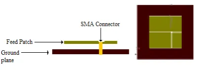
Design of MSA is initialized by specifying antenna parameters and finding its length, width and feed location. For reference antenna, air is used as substrate with 5mm thickness having width and length of 54.8 mm. SMA connector is used for feeding, feed location for antenna 11 mm along length towards right with 0.6mm radius of connector. Antenna resonates at frequency 2.4GHz.Figure 1: Reference Antenna
4.2. Design of 2x2 array MSA
Further the structure modified by introducing 2x2 array on same superstrate cover with length of 52.8mm and width of 54.8mm.parasatic patch length and width 38mm, distance between two parasitic patch i.e. ‘s’ is 0/2.
Figure 2: MSA with 2x2 Array Elements
4.3.Design of 2x2 array MSA
Array structure is further modified as shown in Figure 6 by introducing superstrate cover above superstrate cover containing 2x2 array.
Figure 3: MSA with Multi stacking
5.
RESULTS AND DISSCUSSIONS
Antennas as per design are simulated on software IE3D and the results are presented below. Two types of antennas are simulated viz reference antenna and the MSA with superstrate cover which is one of the method to enhance the gain of MSAs. Results of the antennas are verified and compared by checking five parameters such as return loss, gain, directivity, antenna efficiency and radiating efficiency of the antenna and displayed
5.1. Simulation of reference antenna
Figure.4. Return loss of reference antenna
Figure.5.Gain of reference antenna
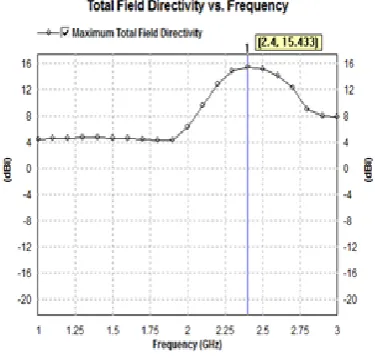
Figure.6. Directivity of reference antenna
Figure.7. Antenna efficiency of reference antenna
Figure.8. Radiating efficiency of reference antenna
5.2.
Simulation of 2x2 array MSA
MSA with superstrate cover design is showed in Figure 4 the simulated results of MSA with superstrate cover contains parasitic patch considering parameters like return loss, gain, directivity, antenna efficiency and radiating efficiency is verified and displayed in Figure.21, Figure.22, Figure.23, Figure.24 and Figure.25 respectively.
Figure.10. Antenna Gain
Figure.11.Directivity of antenna
Figure.12. Antenna Efficiency of Antenna
Figure.13.Radiating Efficiency of Antenna
5.3.
Simulation of Multi stacking MSA
MSA with superstrate cover design is showed in Figure 5 the simulated results of MSA with superstrate cover contains parasitic patch considering parameters like return loss, gain, directivity, antenna efficiency and radiating efficiency is
verified and displayed in
Figure.26,Figure.27,Figure.28,Figure.29 and Figure.30 respectively
Figure.14. Return loss of antenna
Figure.16.Directivity of Antenna
Figure.17. Antenna Efficiency of Antenna
Figure.18.Radiating Efficiency of Antenna
[image:6.595.310.548.155.421.2]In these section simulated results of the reference antenna and all other modified MSA are presented for different parameters which describe earlier at resonating frequency 2.4 GHz. Table 1 is summarized with the comparative study of all antennas considering five parameters as mentioned before.
Table 1. Comparison of antennas with different parameters
Antenna
Parameter
Reference Antenna
2x2 Array Antenna
Multi stacking Antenna
Return Loss (dB) At 2.4GHz
-16.00 -11.40 -10.38
Gain (dB) At 2.4GHz
9.36 13.92 14.52
Directivity (dB) At 2.4GHz
9.538 14.46 15.43
Antenna Eff. (%) At 2.4GHz
96.13 91.32 89.84
Radiating Eff. (%) At 2.4GHz
98.60 94.95 81.15
6.
CONCLUSION
As per the results displayed in Table 1, comparing all the parameters of each modified antenna with the reference antenna parameters, it is observed that there are changes for each parameter as compared to reference antenna. Return loss, antenna efficiency and radiating efficiency decreases because as number of obstacles here it is superstrate cover increases on the path of radiation direction radiating efficiency as well as antenna efficiency tends to decreases. On the other hand these superstrate cover help to enhance the gain and directivity of the antenna which is observed in table 1. With the help of this analysis it is concluded that 2x2 array antenna is more favorable antenna as compared to other two antennas. This is because though multi stacking helps to improve gain and directivity but it affects the return loss and efficiency. For application such as mobile communication, point to point communication 2x2 array MSA is more approving. But there is scope for developing multi stacking antenna which has more efficiency and improved return loss and it can be done by changing height of the superstrate cover, by varying length and width of feed patch etc.
7.
REFERENCES
[1] V. C. Kshirsagar, “Design and development of stacked planar high gain antenna for wireless communication”, M.E. thesis, Mumbai university.
[image:6.595.68.267.524.716.2][3] Chao Sun, Jiu-sheng Li “A Novel Planar Microstrip Array Antenna for WLAN Applications” IEEE conference 978-1-4244-8268-9/11
[4] M.T.Ali, H. Jaafar, S. Subahir and A. L. Yusof “Gain enhancement of air substrate at 5.8 GHz for microstrip antenna array” IEEE conference 978-1-4577-1559-4112 2012
[5] Horng-Dean Chen, Chow-Yen-Desmond Sim, Jun-Yi Wu, and Tsung-Wen Chiu “Broadband High-Gain Microstrip Array Antennas for WiMAX Base Station” IEEE transactions on antennas and propagation, vol. 60, no. 8, august 2012
[6] Tommy Reynalda, Achmad Munir and Endon Bharata “Characterization of 4x4 high gain microstrip array antenna for 3.3 GHz WiMAX application” The 6th International Conference on Telecommunication Systems, Services, and Applications 2011
[7] Halim Boutayeb, Tayeb A. Denidni “Gain enhancement of microstrip patch antenna using a cylindrical electromagnetic crystal substrate” IEEE transactions on antennas and propagation, vol. 55, no. 11, November 2007.
[8] Shi – Wei Qu, Quan Xue “A Y-Shaped Stub Proximity Coupled V-Slot Microstrip Patch Antenna” IEEE antennas and wireless propagation letters, vol. 6, 2007. [9] Jung-han kim, Joong-Kwan Kim, Yong-Jin kim and
Hong- min lee “High gain antenna using parasitic shorted annular patch structure” IEEE Proceedings of Asia-Pacific Microwave Conference 1-4244-0749-4/07 [10]Bahadir Yildirim and Bedri A. Cetiner ”Enhanced gain
patch antenna with a rectangular loop shaped parasitic radiator” IEEE antennas and wireless propagation letters, vol. 7, 2008.
[11]Sudhipta chattopadyay, Jawad Y. Siddiqui and Debatosh Guha “Rectangular microstrip patch on a composite dielectric substrate for high gain wide beam radiation patterns” IEEE transactions on antennas and propagation, vol. 57, no. 10, October 2009.
[12]Dongying Li, Szabo, Z.Xianming Qing, Li.E.P. Zhi Ning Chen “High Gain Antenna with an optimized metamaterial inspired superstrate” IEEE Transactions on Antennas and propagation 12/2012; 60 (12): 60186023. DOI :10.1109/TAP.2012.2212231
[13]Avinash R. Vaidya “Effect of Superstrate Height on Gain of MSA Fed Fabry Perot Cavity Antenna “2011 Loughborough Antennas & Propagation Conference, Loughborough, UK, 14-15 November 2011.
[14]Siew bee yeap and Zhi Ning Chen “Microstrip patch antennas with enhanced gain by partial substrate removal” IEEE transactions on antennas and propagation, vol. 58, no. 9, September 2010
[15]V. Priyashman, M.F. Jamlos, H.Lago, M. Jusoh, Z. A. Ahmad, M. A. Romli and M.N. Salimi ‘Effect of superstrate on the performance of an elliptical shaped antenna without dots “ IEEE Symposium on Wireless Technology and Applications (ISWTA), September 23-26, 2012, Bandung, Indonesia
[16]K.P. Ray and G. Kumar, “Broadband Microstrip Antennas”, Archtech House, ISBN: 1-58053-244-6, 2003.