CAN based Boot Loader using PSoC 5
Rajasekhara Reddy Challa
JNTU-Hyderabad, M.Tech VARDHAMAN College of Engineering,
Hyderabad, India
Krishna Chaitanya Janapati
JNTU-Hyderabad, Associate Professor (PhD), VARDHAMAN College of Engineering,
Hyderabad, India
ABSTRACT
In this paper, we describes how to use PSoC Creator™ in building of CAN-based boot loader applications and working flow of boot loader (its requirements) to create CAN communication between host and Psoc5.The complete system design is constrained on two different theories named wired and wireless. In UART and USB the communication is wired, so these can’t accommodate longer distance communication and speeds (Full UART mode data rate is 57600 bps) are less. In I2C and SPI communications between PSoC is wireless and invisible i.e. Flow of data and the speed is good enough. The complete design is isolated on a single PCB with multiple ICs (master and slave ICs) respectively.
Keywords:
pSoC Creator, CAN, boot loader, host, PSoC5.1.
INTRODUCTION
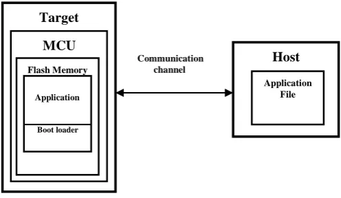
Bootloaders are a common part of Micro Controller Unit system design. A boot loader provides the facility for the developer for the up gradation of the product's firmware in the field. During the manufacture of the product at the factory, initial programming of firmware into a product is typically done through the MCU's Joint Test Action Group (JTAG) or Serial Wire Debugger (SWD) interface. However, these interfaces are usually not accessible in the customer site. This is where boot loader comes into the picture. Bootloading is a process that allows upgrading system’s firmware over a standard communication interface such as USB, I2C, UART or SPI [7]. The paper describes design and development of CAN based boot loader. It communicates with the host to get new application code or data, and writes it into the device's flash memory. Here, the discussion leads to two different issues among those one, the basic building blocks and functionality of a CAN boot loader. Second, how to establish a CAN communication between boot loader and PSoC Creator of PSoC 5.Figure 1 illustrates the main elements in a bootloadable system. It shows that the product's embedded firmware must be able to use the communication port for two different purposes – normal operation and updating flash. The portion of the embedded firmware that knows how to update the flash is called a bootloader. The Target embedded system must have the microcontroller or microprocessor as its core element which controls and monitors the whole system, which takes the input from the external environment from input devices such as sensors and controls the operation of the entire system. The memory in the microcontroller unit is one of the main constraints during consideration of controllers during the design of the embedded products. The memory of the microcontroller unit is divided into different parts among those one is called flash memory, in which generally flashed program is stored. The flash program is again classified into boot loader part and application part. Boot loader resides in the Boot loader region and boot loadable application is stored
[image:1.595.325.573.254.398.2]in the application memory region. The memory size of the Boot loader and application memory regions is varies from the microcontroller to microcontroller.
Figure 1: Boot loading System Diagram
The system which provides the data to update the flash is called the host, and the system being updated is called the target. The host can be an external PC or another MCU (such as PSoC 5LP) on the same PCB as the target. The act of transferring data from the host to the target flash is called bootloading, or a bootload operation, or just bootload for short. The data that is placed in flash is called the application or bootloadable. A bootloader communication port is typically shared between the bootloader and the actual application. The procedure is as follows,
Step 1: Need to check whether the product is executing boot loader or not.
Step 2: Once the boot loader is running, the host can send a "start boot load" command over the communication channel.
Step 3: If the boot loader sends a "+VE" response as, (+VE Frame Format)
During boot loading, the host reads the *.cyacd file (cyacd file means cypress application code file) for the new application, parses it into flash write commands, and sends those commands to the bootloader. After the entire file is sent, the bootloader can pass control to the new application. The application which is running on the target is observed in the output device of the PSoC 5 development kit.
2.
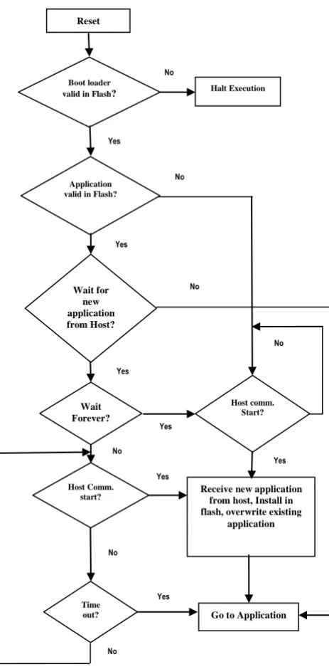
BOOT LOADER FUNCTION FLOW
Typically when the device resets, the bootloader is the first function to execute. It then performs the following actions:
Checks the application's validity before letting it runs
Host
Application File Target
MCU
Flash Memory
Application
Boot loader
Manages the timing to start host communication
Do the boatload / flash update operation
Finally, passes control to the application
After reset start CAN component by calling CAN start () function. This function sets CAN Component into Run mode and starts the rate Counter if polling mailboxes available and then call bootloader start () function, all the bootload-related tasks are called from this function. This method will never return. It will either load a new application or reset the device or it will jump directly to the existing application’s boot loader Start function checks for boot loader validation.
If the system is disturbed by external constraints then, the boot loader performs as
Calculated checksum does not much one stored in metadata section
Invalid pointer to the place where bootloader application ends
Flash subsystem where not initialized correctly
If valid boot loader application is in flash then it checks for active boot loadable application validation and application is not valid in flash go to the communication subroutine vice versa. It will wait for commands forever until host communication starts. If host starts communication to receive new application from host, install in flash and overwriting existing application. If timeout, boot loader jump to boot loadable application otherwise boot loader continuously looking for communication start with host until timeout and within this specified time host need to start communication then, target receives new application from host, overwrites existing application, resetting the Psoc5 and jump to bootloadable application.
The CAN peripheral is a fully functional Controller Area Network, supporting communication in baud rates up to 1 Mbps at 8 MHZ of frequency. The CAN protocol was originally designed for automotive applications with a focus on high level fault detection and recovery. This ensures high communication reliability at low cost[6]. Because of its success in automotive applications, CAN was adopted as a standard communication protocol for motion oriented embedded control applications (CAN Open) and factory
automation applications (Device Net). Figure 2 .flow diagram of boot loader
[image:2.595.340.572.75.546.2]3. PROPOSEDCOMMUNICATION
BETWEEN HOST AND TARGET
3.1 Block Diagram
Figure 3 Block diagram of complete setup
The PSoC5 hardware board (CY8CKIT-050)[2] with CAN/LIN expansion kit (CY8CKIT-017) [3] is considered as the complete target board, it is not necessary to power the board from the separate power supply or a battery. We can
PC with PSoC Creator and
CANAlyzer Tool
VECTOR CAN Data Logger
Device
PSoC5 Target Board
USB UART
Reset
Boot loader valid in Flash?
Application valid in Flash?
Host Comm. start?
Time out?
Wait Forever? Wait for
new application from Host?
Halt Execution
Go to Application Receive new application
from host, Install in flash, overwrite existing
application
Host comm. Start?
start
cation start No
Yes
No
Yes
Yes
No
No
Yes
Yes No
No
No
Yes
[image:2.595.303.561.576.692.2]use the USB power to the programming section. The interface between the target and personal computer is Vector CAN data logger device which is used to observe the CAN Frames communication between host and the target and also provides the log data of the frames. Due to this kind of Interface, the reliability of the communication can achieve with low cost. The main requirement for observing the CAN Frames in computer, the user needs to install the CANALYZER tool in their PC.PSOC Creator is required for developing the CAN based boot loader and to debug the operation, which is works just as a IDE(integrated Development Environment).
3.2 Construction of Can Frames
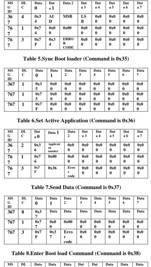
Each CAN Frame consists of information regarding mainly 3 things. Those are message ID, data length and data[6]. Again message IDs are of 2 types, those are either standard ID (which represented by 11 bits) or extended ID (which represented by 29 bits).Data length is always less than or equal to 8 bytes. Each CAN frame can send 8 bytes of data. For identification purpose we have considered 2 types of IDs those are 0x367 and 0x767(There is no any specific reason for selecting only 367 and 767 as message identifiers) .Message ID 0x367 is used for sending the CAN frames to the target from the host. The response frames from the target to the host is received with message ID 0x767. Both the way of CAN frames communication we can observe in the CAN Analyzer tool in the host. The response from the target for any command may be either positive or negative. The frames whose Data0 field is 0x7F are considered as negative response and Data0 have any other data are considered as positive response. The frames constructed for every command and its positive and negative responses are represented bellow.
Table 1.Verify Checksum (Command is 0x31)
Ms G ID DL C Dat a 0
Data 1 Data 2 Dat a 3 Dat a 4 Dat a 5 Dat a 6 Dat a 7
367 1 0x3
1
0x00 0x00 0x0
0 0x0 0 0x0 0 0x0 0 0x0 0
767 2 0x7
1
Checksu m
0x00 0x0 0 0x0 0 0x0 0 0x0 0 0x0 0
767 3 0x7
F
0x31 Erro
[image:3.595.304.552.92.530.2]r code 0x0 0 0x0 0 0x0 0 0x0 0 0x0 0
Table 2.Get Flash Size (Command is 0x32)
MS G ID DL C Data 0 Data 1 Data 2 Data 3 Data 4 Data 5 Data 6 Data 7
367 2 0x3
2 Arra y Id 0x0 0 0x0 0 0x0 0 0x0 0 0x0 0 0x0 0
767 5 0x7
2 MS B
LSB MS
B LS B 0x0 0 0x0 0 0x0 0
767 3 0x7
F
0x32 Erro r code 0x0 0 0x0 0 0x0 0 0x0 0 0x0 0
Table 3.Get Application Status (Command is 0x33)
MS G ID DL C Dat a 0
Data 1 Dat a 2 Dat a 3 Dat a 4 Dat a 5 Dat a 6 Dat a 7 36 7 0x3 3 Applicat ion number 0x0 0 0x0 0 0x0 0 0x0 0 0x0 0 0x0 0 76 7 0x7 3
0x00 0x0
0 0x0 0 0x0 0 0x0 0 0x0 0 0x0 0 76 7 0x7 f
0x00 0x0
[image:3.595.312.547.92.176.2]0 0x0 0 0x0 0 0x0 0 0x0 0 0x0 0
Table 4.Erase Row (Command is 0x34)
MS G ID DL C Data 0 Dat a 1
Data 2 Dat a 3 Dat a 4 Dat a 5 Dat a 6 Dat a 7 36 7
4 0x3
4 AI D
MSB LS
B 0x0 0 0x0 0 0x0 0 0x0 0 76 7
1 0x7
4 0x0 0 0x00 0x0 0 0x0 0 0x0 0 0x0 0 0x0 0 76 7
3 0x7
F 0x3 4 ERRO R CODE 0x0 0 0x0 0 0x0 0 0x0 0 0x0 0
Table 5.Sync Boot loader (Command is 0x35)
MS G ID DL C Data 0 Data 1 Data 2 Data 3 Data 4 Data 5 Data 6 Data 7
367 1 0x3
5 0x0 0 0x0 0 0x0 0 0x0 0 0x0 0 0x0 0 0x0 0
767 1 0x7
5 0x0 0 0x0 0 0x0 0 0x0 0 0x0 0 0x0 0 0x0 0
767 1 0x7
F 0x0 0 0x0 0 0x0 0 0x0 0 0x0 0 0x0 0 0x0 0
Table 6.Set Active Application (Command is 0x36)
MS G ID DL C Dat a 0
Data 1 Data 2 Dat a 3 Dat a 4 Dat a 5 Dat a 6 Dat a 7 36 7
2 0x3
6 Applicati on number 0x0 0 0x0 0 0x0 0 0x0 0 0x0 0 0x0 0 76 7
1 0x7
6 0x00 0x0 0 0x0 0 0x0 0 0x0 0 0x0 0 0x0 0 76 7
3 0x7
F 0x36
Erro r code 0x0 0 0x0 0 0x0 0 0x0 0 0x0 0
Table 7.Send Data (Command is 0x37)
MS G ID DL C Data 0 Data 1 Data 2 Data 3 Data 4 Data 5 Data 6 Data 7
367 8 0x3
7
Data Data Data Data Data Data Data
767 1 0x7
7 0x0 0 0x00 0x0 0 0x0 0 0x0 0 0x0 0 0x0 0
767 3 0x7
F 0x3 7 Erro r code 0x0 0 0x0 0 0x0 0 0x0 0 0x0 0
Table 8.Enter Boot load Command (Command is 0x38)
MS G ID DL C Data 0 Data 1 Data 2 Dat a 3 Dat a 4 Data 5 Data 6 Data 7 36 7
1 0x3
8 0x00 0x0 0 0x0 0 0x0 0 0x0 0 0x00 0x00 76 7
8 0x7
8
SID SID SID SID SRE
V BRE V BRE V 76 7
2 0x7
8 BRE V 0x0 0 0x0 0 0x0 0 0x0 0 0x00 0x00 76 7
3 0x7
F 0x38 Erro r Cod e 0x0 0 0x0 0 0x0 0 0x00 0x00
Table 9.Program Row (Command is 0x39)
MS G ID DL C Data 0 Data 1 Data 2 Data 3 Data 4 Data 5 Data 6 Data 7
367 0x3
9
767 1 0x7
9 0x0 0 0x00 0x0 0 0x0 0 0x0 0 0x0 0 0x0 0
767 3 0x7
[image:3.595.309.549.519.638.2]Table 20.Verify Row (Command is 0x3A)
MS G ID
DL C
Data
0 Data 1
Data 2
Dat a 3
Dat a 4
Dat a 5
Dat a 6
Dat a 7
36 7
4 0x3
A
Array ID
MS B
LS B
0x0 0
0x0 0
0x0 0
0x0 0
76 7
2 0x7
A
Row Checksu m
0x0 0
0x0 0
0x0 0
0x0 0
0x0 0
0x0 0
76 7
3 0x7
F
0x3A Erro
r Cod e
0x0 0
0x0 0
0x0 0
0x0 0
0x0 0
Table 31.Exit Boot loader (Command is 0x3B)
MS G ID
DL C
Data 0
Data 1
Data 2
Data 3
Data 4
Data 5
Data 6
Data 7
367 1 0x3
8 0x0 0
0x0 0
0x0 0
0x0 0
0x0 0
0x0 0
0x0 0
767 1 0x7
8 0x0 0
0x0 0
0x0 0
0x0 0
0x0 0
0x0 0
0x0 0
767 1 0x7
F 0x0 0
0x0 0
0x0 0
0x0 0
0x0 0
0x0 0
0x0 0
4.
TX/RX FULL CAN MESSAGE
We are transmitting response packet from Psoc 5 to host using full CAN message.CAN_TX_Struct is defined for the generic structure, where all message parameters are specified. It represents the base address of the CAN transmit buffer. The CANTX _Struct matches the order in which the CAN registers are available in the PSoC 3/PSoC 5. Therefore, it is used to access the CAN transmit registers directly. The CANTX struct is declared in the CAN.h file. The format of the structure is as follows.
typedef struct _CANTX_Struct {
CAN_reg32 txcmd; CAN_reg32 txid; DATA_BYTES txdata; } CANTXstruct;
When the message is received in a buffer, the received interrupt is triggered if the IRQ bit of that buffer is set to 1. The receive message ISR (CAN_MsgRX_ISR) automatically calls the corresponding CAN receive message function is as shown
Void CAN_MsgRX_ISR (Void) {
. .
/* RX Full mailboxes handler */ switch(i)
{
case 2u : CAN_ReceiveMsgX(); break;
. . default: break; }
}
CAN_ReceiveMsgX() which is defined in
CAN_TX_RX_func.c is used to retrieve data from the received message frame. “X‟ corresponds to the message buffer configured as ‘Full’. CAN_RX is defined for the
generic structure CANRX_Struct from which all CAN message parameters are obtained. The format of the structure is same as the CAN_TX_Struct. To retrieve data using the API CAN_ReceiveMsgX () in CAN_TX_RX_func.c, write the appropriate code inside the function.
void CAN_ReceiveMsgBoot_cmd(void) {
flag=1;
for ( i = 0; i < 8; i++ ) {
CAN_RxBuffer[RxBufIndex]= CAN_RX_DATA_BYTE(2, i); RxBufIndex++;
}
CAN_RX[2u].rxcmd.byte[0u]|= CAN_RX_ACK_MSG;
}
The CANRXstruct matches the order in which the CAN registers are available in PSoC 3 and PSoC 5. Hence, the CAN_RX define can be used to access the CAN receive registers directly. The CANRXstruct is available in the CAN.h file. The format of the structure is as follows.
typedef struct _CANRXstruct {
CAN_reg32 rxcmd; CAN_reg32 rxid; DATA_BYTES rxdata; CAN_reg32 rxamr; CAN_reg32 rxacr; CAN_reg32 rxamrd; CAN_reg32 rxacrd; } CANRXstruct;
Where, DATA_BYTES is a structure that represents eight bytes of data. The structure is as follows.
typedef struct _DATA_BYTES {
reg8 byte[8]; } DATA_BYTES;
void CAN_MsgRXIsr(void) {
…
/* RX Full mailboxes handler */ switch(i)
{
case 0 : CAN_ReceiveMsg0(); break;
case 2 : CAN_ReceiveMsg2(); break;
.
.
.
default: break;
}
…
}
{
CAN_reg32 rxcmd; CAN_reg32 rxid; DATA_BYTES rxdata; CAN_reg32 rxamr; CAN_reg32 rxacr; CAN_reg32 rxamrd; CAN_reg32 rxacrd; } CANRXstruct;
5. RESULTS & DISCUSSION
By using the CY8CKIT-050 PSoC 5LP Development kit along with CY8CKIT-017 CAN/LIN Expansion kit the boot loadable application is successfully flashed on to the Target hardware without using either JTAG interface or serial wire debugger. The boot loadable application which is running on the target is observed through the message on the LCD display of the CY8CKIT-050 PSoC5LP Development kit. The log data of the CAN commands communication between the host and target during boot loading operation is observed on the CAN analyzer tool make sure that which installed in the host PC. Due to this we can achieve the high level fault detection and recovery. This ensures high communication reliability at low cost. By this kind of boot loaders we can easily update application firmware of the target, which is presented at the customer sites.
6. CONCLUSION
In this paper, introduction and implementation of CAN based boot loader for automobile industry is elaborated in detail. The CAN based boot loader system takes CY8CKIT-050 PSoC 5LP development kit and CY8CKIT-017 CAN/LIN Expansion kit as the hardware base, supports the CAN and LIN protocols.The hardware of this kit includes transceiver circuits for CAN and LIN interfaces. We can design our own projects with aneasy to use CAN and LIN slave components in PSoC Creator software or by altering code examples provided with this kit. By monitoring the receive and
transmitting messages between the target and host we can successfully flash the new application on to the target at the field level without using any embedded debuggers assistance and we can achieve high level communication with more reliability than existing techniques.
7. ACKNOWLEDGEMENT
The authors wish to thank Autoliv India PVT Limited for providing the Internship opportunity, cooperation on utilization of resources (CAN Analyzer tools, PSoC 5 DVK, Boot loader host user interface software) and helpful suggestions, which greatly improved the quality of this paper.
8. REFERENCES
[1] PSoC® 4 I2C Bootloader – Cypress, Available: http://www.cypress.com/?docID=48766
[2] CY8CKIT-050 PSoC® 5 Development Kit Guide –
Cypress, Available:
http://www.cypress.com/?docID=46949
[3] CY8CKIT-017 CAN/LIN Expansion Board Kit Guide, Available: www.farnell.com/datasheets/1712465.pdf
[4] Mark Ainsworth; PSoC® 3, PSoC 4, and PSoC 5LP –
Introduction to Bootloaders, Available:
http://www.cypress.com/?docID=50276
[5] VN1600 Interface Family - Vector, Available: www.vector.com/portal/.../VN1600_Interface_Family_M anual_EN.pdf
[6] CAN with Flexible Data-Rate, Available:
http://www.boschsemiconductors.de/media/pdf_1/canliter atur/can_fd_spec.pdf
[7] AN73503 - USB HID Bootloader for PSoC® 3 and PSoC
5LP - Cypress, Available: