A One Wheel Flying Robot
Soumya Das
Dept. Of E.C.E. Bengal Institute of TechnologyWBUT
Kousik Maity
Dept. Of E.C.E. Bengal Institute of TechnologyWBUT
Debarati Dey
Dept. Of E.C.E. Bengal Institute of TechnologyWBUT
ABSTRACT
Recent advances in technology have lead to growing interest in robotic application. More recently, a growing interest in unmanned aerial vehicles (UAVs) has beenshown among the research community. Being able to design avertical takeoff and landing (VTOL)-UAV, which is highly maneuverable and extremely stable, is an important contributionin the field of aerial robotics since potential applications are tremendous (e.g., high buildings and monuments investigation, rescue missions, film making, etc.). For the navigation and military purpose their mainly two type of robot use: multi or single wheel robot and flying robot .But each type has certain limitation, to overcome from that here we have propose a novel concept of a robot called OWFR(one wheel flying robot) base on the Vertical takeoff and landing(VTOL) mechanism. OWFR can land on its single wheel .It can pass from a very narrow road as it has only one wheel. By simulation we have shown that it will efficiently land and fly in its single wheel and thus it is better than previous type of robots.
Keywords
Gyroscopic, single wheel robot, Vertical Take Off and Landing (VTOL), flying robot.
1.
INTRODUCTION
Robots are “An electro-mechanical device which is capable of reacting in some way to its environment, and take autonomous decisions or actions in order to achieve a specific task."
Multi or Single wheel robot
In the single or multi wheel robot the main purpose of wheel is to give the stable movement. The invention of the wheel was, without a doubt, a revolutionary step in the development of transport, with the improvement of wheel all the transport vehicle quality is improving.Today the use of microcontrollers is introduce a new systems that capable of autonomous operations. Now a days different type of wheel robot are develop and those are one or multi wheel robot. Example of this type of robots are Gyrover, Gyrobot,murata girl, The Gyrover which is created by CMU and the Gyrobot which is created by NUS. Are both single wheel robot that are got stability by using mechanical gyroscopes[1]and the main advantage of using gyroscope is the robot can move any direction or any angle .More recently the development of a reaction wheel stabilized unicycle robot murata girl was announced by murata manufacturing co .Ltd. zenkov et.al modal the case of a unicycle with a rider as a two link inverted pendulum and demonstrate that the system can be stabilized by controlling the motion of the second link in the
unbalance and changes heading by turning the wheel axis. Numerous robots with four or six(or more) wheels have been developed to maximize mobility on rough terrain. like Bekker in 1974, Freitag in 1979,Kemurdjian et al in 1992,Klarer in 1994.But in the wheel robot some drawback is there and those are when a situation is arise that in the particular road wheel robot can’t be move there is no option to move forward the robot and solution of this problem come by using flying robot.
Flying robot
The rest of the paper is organized as follow: in the second section we have described the related robots that are already made and corresponding advantages and disadvantages. In the third section we have described the details of our OWFR robot its main features and the challenges and corresponding solutions. In the forth section we have simulated the performance of our OWFR in different conditions. The simulation results of OWFR are based on the landing performance in different types of ground positions. Then we have concluded the whole paper and finally a future work is mention regarding this paper in section seven.
2.
RELATED WORK
Gyroscopically Stabilized Robot:
Self-stabilization of a single rolling wheel using a gyroscopic actuation was under several explorations for its importance in robotic applications and the mechanical design consists basically of a gyro disk attached to internally suspended pendulum. Such arrangement provides a forward and reverse movement in which the reaction of the applied motor torque is counteracted by the moment of the hanging mass of the gyroscope as shown in Figures1.
Fig:1 Balance using the effect of gyroscopic precession induced by the applied torque.
[image:2.595.319.542.73.259.2]The behavior of gyrover is based on the principle of gyroscopic precession as exhibited in the stability of a rolling wheel. Because of its angular momentum, a spinning wheel tends to process (its axis) at right angles to an applied torque, according to the fundamental equation for gyroscopic precession, T = Jω ×Ω where ω is the angular speed of the wheel, Ω is the wheel's precession rate, normal to the spin axis, J is the wheel polar moment of inertia about the spin axis, and T is the applied torque, normal to the spin and precession axes [2][6].
Fig: 2 The basic configuration of Gyrover
Figure 2 shows a schematic representation of the mechanism design [2][5]. In brief, the robot is a sharp-edged wheel, inside of which an actuation mechanism is fitted. The actuation mechanism consists of three separate actuators:
(1) A spin motor, which spins a suspended flywheel at a high rate, imparting dynamic stability to the robot;
(2) A tilt motor, which controls the steering of the robot; and
(3) A drive motor, which causes forward and/or backward acceleration, by driving the single wheel directly.
Vertical takeoff and landingflying robot: UNMANNED vehicles are important when it comes to performing a desired task in a dangerous and or inaccessible environment. Unmanned indoor and outdoor mobile robots have been successfully used for some decades. More recently, a growing interest in unmanned aerial vehicles (UAVs) has been shown among the research community. Being able to design avertical takeoff and landing (VTOL)-UAV, which is highly maneuverable and extremely stable, is an important contribution to the field of aerial robotics since potential applications are tremendous (e.g., high buildings and monuments investigation, rescue missions, film making, etc.). In practical applications, theposition in space of the UAV is generally controlled by an operator through a remote-control system using a visual feedback from an onboard camera, while the attitude is automatically stabilized via an onboard controller. The attitude controller [11] is animportant feature since it allows the vehicle to maintain a desired orientation and, hence, prevents the vehicle from flipping over and crashing when the pilot performs the desired maneuvers.
The most common configuration of vertically take off and vertically landing fly robot is the helicopter [8][10]. The helicopter is capable of true vertical flight, including the ability to hover in place, fly forward and aft and from side to side unfortunately; the helicopter has many limitations and those are
(1)The area should be big enough for the helicopter to land within.
[image:2.595.56.280.323.473.2]3.
PROPOSED WORK
In our paper we have proposed a new type of robot named One Wheel Flying Robot (OWFR) which is capable of flying and landing in its one wheel. This robot can run in a very narrow path and can also land and take off on a very narrow ground.
FEATURES OF OWFR
The main features of our proposed OWFR are
It can fly up to 10 meters from ground using its flying instruments. It can be fly above 10 meter but when we control the robot through remote to fly very high altitude communication in between robot and remote should be very strong. How communication between robot and remote can be improve we will concentrate on that on future work.
It uses the Vertical Takeoff and Landing mechanism (VTOL) to fly.
Its can land on its single wheel which is the main characteristics of OWFR and landing in one wheel is the most challenging work because in the time of landing on ground robot should be stable.
[image:3.595.318.552.73.430.2] It can pass from a very narrow road like fig:3 as it has only one wheel.
Fig: 3 Narrow road
CHALLENGES OF OWFR
The main challenge of OWFR is to
Take off safely through its one wheel because in the time of take-off robot should be stable and also upper surrounding environment should be obstacle free.
Land safely on a narrow path on its one wheel is an very challenging task.
SOLUTION OF CHALLENGES
To overcome the main challenge in the following we have given two algorithm and flowchart of Take-off and landing mode respectively.
3.1 Terminologies
The following terminologies we have used in our algorithm.
Ld: Distance from the land.
Fig 4: The Algorithm of take of mode of OWFR
Algorithm for take-off mode:
Step 1: As we are controlling OWFR through remote if it needs to take-off from ground first it checks whether robot is in stable condition. if it is in stable condition then it follow next step. if it is not in stable condition then it move from that place for some distance and then again check it stability condition.
Step 2: In this step it checks is upper surrounding view obstacle free? [if we don't check whether upper surrounding area is obstacle free or not then OWFR cannot take-off properly. So for that use of camera is very impotent].If upper surrounding is free, then it goes to step 4. Else it goes to step 3
Step 3: OWFR move 2 meter through one wheel and then repeatedly again it check is upper surrounding view obstacle free? if, yes then it go farther step. otherwise again it repeated from step2.The distance can be take any value, we have taken 2 m because if a obstacle is in there on the upper surround normally it do not take more than 2 meter.
Step 4: In this step robot spread its four supporting arms R1, R2, R3 & R4 mainly to stable the robot. In the time of Take-off as the fly motor start working so robot can unstable or fallen down on ground so to give stability we use four supporting arms.
[image:3.595.53.280.351.539.2]Step 6: In the flying time it Furl the four wheels otherwise it four wheel take some extra area and that may be create problem. for that it furl it's four wheel.
[image:4.595.56.278.148.327.2]Step 7: As OWFR can only capable to fly upto 10 meter so In this step it Check is the altitude Ld<10 m ?, If yes, then increase the altitude. If no, robot flies parallel to ground.
Fig: 4 CASE 1:
In this case 1 also we have taken that the robot in the time of landing mode .when checking whether four supporting arms and find those are in unstable condition.
Here as the arms are in unstable condition first rotation of 10 degree in clockwise happen and then the robot arms goes in stable condition so here landing mode is possible.
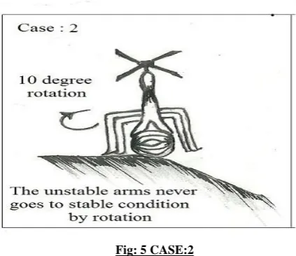
Fig: 5 CASE:2
In case 2 we have assume all four unstable arms goes stable condition in only one rotation .But rotation can be any times but maximum 36 times.
In this case we have taken that the robot in the time of landing mode. when checking whether four supporting arms and find tousle are in unstable condition.
As the arms are in unstable condition first those arms rotate 10 degree clockwise. But then also arms are in unstable condition and again rotation happen. In this way 36 time rotation done[ 10*36=360 so four arms have rotated total surround] If then also arms are in unstable condition then in
that position OWFR will not land it cancel its land mode .and again it goes in flying mode.
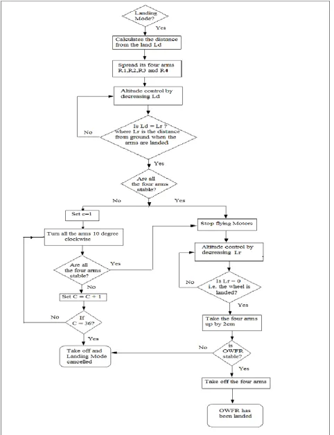
ALGORITHM OF LANDING MODE:
Step1: When the OWFR need to land on the ground first it check whether the landing mode is activated or not? If the landing mode is activated then it check through camera is the area where the robot is going to land suitable, if it finds that the land below is suitable for landing then it goes for further step .if it finds some water or something not suitable for landing then it move some distance again check for suitable place. It will do this until it gets the suitable place.
Step 2: In this step first it calculates the distance from the land (Ld) to itself. This step is a very impotent step for landing so need very accurate calculation.
Step3: After knowing the distance from land OWFR spreads its four supporting arms R1, R2, R3 & R4 because in the time of landing robot should be in stable condition so to give the stability four arms are use. These four arms 90 degree apart from each other and the angle between each arm to the wheel of OWFR is 60 degree. These are to give the stability if the land is not smooth.
Step4: After spreading the arms the distance from land is decreased by altitude controller. Ld is decreased gradually and altitude controller check is Ld=Lr? where Lr is the distance from ground when arms are landed. Each time the OWFR is decreased by 0.5cm and it checks the above condition.
If the condition is satisfied then it goes to step 5.
If not satisfied, then again it goes back to step 4 and decrease distance from ground and again check Ld=Lr? This process will continue until both distances are same.
Step5: Now after landing the system checks if the OWFR is stable or not? Actually it checks if all the four arms are touching the ground and the wheel is also touching or not. There may be cases where the three arms and the wheel are touching the ground and the other arm is not touching. So this will be a unstable condition as described earlier. Now if the system finds that OWFR is stable then it goes to step 7. If OWFR is unstable then
Set c=1.
Turn all the arms 10 degree clockwise. We can turn the arms in any degree .we take 10 degree so in 36 time it move 360 degree.
Again the system checks are all four arms stable?
If again it finds OWFR is unstable then
, set c=c+1, and
[image:4.595.56.268.410.593.2]landing mode will be cancel. If any position the system finds that OWFR is stable then it stops its stop flying motor and landed completely.
Step 6: Now if c=36 mean it rotates completely 360 degree then it comes to its 1st position itself. Now there is no landing condition so the take off mode is activated and the landing mode is cancelled. Now the OWFR will find another suitable condition for landing.
Step7: Now when the OWFR is stable the flying wheels are stopped. Altitude controller decreased by decreasing the distance from the wheel to land i.e. l Lr. Each step Lr is decreases by 0.1cm. Now the system checks if check is Lr=0 ? [i.e the wheel is landed?] If OWFR is landed then the system goes to step 8. This loop is continued until Lr=0.
Step8: Now after landing the system checks is OWFR stable? If it is found to be stable i.e. the wheel landed properly and if the wheel can control the OWFR now then the system takes off the four supporting arms. This is done by the procedure by checking the stability like 1st the system take off two opposite arms by 2cm and check whether robot is stable if stable then it take off another two arms. This is done to find that if the system is table with the single wheel. If the system not stable it goes back to step 6 where the landing mode is canceled.
Step9: Now after taking off the four arms the system does its works by the single wheel. Thus the OWFR is landed successfully.
[image:6.595.318.535.73.342.2]FLYING MODE OF OWFR:
Fig 7: Flying modes of OWFR
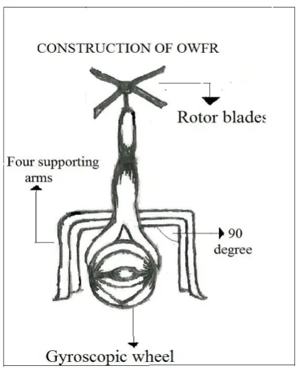
Construction of OWFR:
Gyroscopic Wheel
[image:6.595.56.283.375.559.2]A gyroscope is a device for measuring or maintaining orientation, based on the principle of angular momentum. Mechanically, a gyroscope is a spinning wheel. In OWFR gyroscope is the only one wheel we used.
Fig 8: Construction of OWFR Rotor Blades
The blades of OWFR are long, narrow airfoils with a high aspect ratio, a shape which minimizes drag from tip vortices (see the wings of a glider for comparison). They generally contain a degree of washout to reduce the lift generated at the tips, where the airflow is fastest and vortex generation would be a significant problem. Rotor blades are made out of various materials, including aluminum, composite structure and steel or titanium with abrasion shields along the leading edge. Rotorcraft blades are traditionally passive.
Supporting arms
Four supporting arms R1,R2,R3 &R4 are there in OWFR. Mainly those are used to stabilize the robot. In the algorithm of landing we have use Lr. where Lr initial value is the height of supporting arm.
Camera
In OWFR camera is an very important part. Mainly CCD video camera is use to see the landscape means to view the surrounding environment.
Altitude Controller
4. SIMULATION RESULTS
[image:7.595.318.541.101.269.2]In order to evaluate the performance of the new algorithm on VTOL, we compared in between probability of landing verses smoothness of the land, Number of times it rotated verses smoothness of the land and Time taken to land verses smoothness of the land. The simulation results were run on MATLAB 7.8 in a designed virtual environment
.
Fig-9: Simulation results of how the probability of landing varies accordingly to the smoothness of the ground
In figure-9 we compared in between probability of landing verses smoothness of the land. From the result we conclude that with the increase of smoothness of land, the probability of landing become high. when smoothness of land is perfect means 100(in percentage) the probability of landing become nearly 1 and when the smoothness of land is very bad means nearly 0 (in percentage) then landing probability become nearly zero. In this operation camera plays very key role because if somehow camera can
n
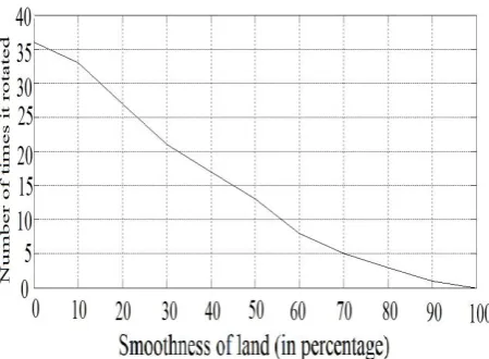
ot capture inpicture of land then all the entire system cannot work properly.Fig-10 Simulation results of how many times OWFR rotate with respect to ground nature
In figure-10 we plotted in between Number of times it rotated verses smoothness of the land. The graph nature like gradually decreasing means with the increase of smoothness of land, the
mechanism is applied when four supporting arms are not in stable condition.
[image:7.595.57.263.167.353.2]Fig 11: Simulation results of how much time OWFR will take to land
In figure-11 we have shown the simulation results between The time taken to land(in minute) verses smoothness of the land. The graph says that with the increase of smoothness of land, the time taken to land the robot is decrease .when the smoothness of land is very bad simulation says near about 9 minute is required to land the robot but if land is perfect than time required by robot is only few seconds. so we have found that OWFR will more efficient than previous type of robot.
5. CONCLUSION
In this paper we have proposed OWFR (one wheel flying robot). It uses the Vertical Takeoff and Landing mechanism (VTOL) to fly .we have proposed an algorithm for vertical Takeoff and an algorithm for landing mechanism.
We first described Gyroscopically Stabilized single wheel Robot. Then flying robot then Vertical takeoff and landing flying robot. Then we described our OWFR and its main feature. It’s main challenge. Then we have how those challenge can be solved .we have shown the specific algorithm and flowchart of Take-off mode and landing mode respectively.Then we have simulated the OWFR with respect to ground nature and we have shown that the probability of landing it varies accordingly to the smoothness of the ground.
We have also calculated the number of times it rotated according to the smoothness of the ground. In our final simulation we have calculated the time required to land which is also a function of the smoothness of the ground. These results shows that OWFR is working every effectively.
6. FUTURE WORK
[image:7.595.55.280.500.665.2]7. REFERENCES
[1]. Brown, H. B., and Xu, Y. 1996. A single wheel gyroscopically stabilized robot. Proc. IEEE Int. Conf. on Robotics and Automation 4:3658–3663.
[2] Xu, Y.; Brown, H. B. &, Au, K. W. (1999), Dynamic Mobility with Single-Wheel Configuration, The International Journal of Robotics Research., Vol. 18, No. 7, pp. 728-738.
[3] Aria Alasty and Hodjat Pendar “Equations of motion of a Single-wheel robot in a Rough Terrain” IEEE ICRA, April 2005 Spain
.
[4] Xu, Yangsheng and Brown, Ben “gyroscopically Stabilized and Controlled Single-Wheeled Autonomous Vehicle” Conference on Recent Advancements in Robotics, Florida USA, 2000.
[5] Cavin, R. D. (2001), Gyroscopically Stabilized and Controlled Single-Wheeled Autonomous Vehicle,
[6] Gora C. Nandy and Yangsheng Xu: “Dynamic model of a gyroscopic wheel” international conference on robotics and automation Leuven, Belgium May 1998.
[7] Xu Y., Ou Y., 2002, Balance control of a single wheel robot, Proceedings of the 2002 IEEE/RSJ International Conference on Intelligent Robots and Systems, Switzerland
[8] O. Amidi, “An Autonomous Vision-Guided Helicopter,” (M.A. thesis,Carnegie Mellon University, 1996.
[9] Zhu Zhen, A. Al-Mamun and Myint Phone Naing:
“CONTROL-CENTRIC SIMULATOR FOR
MECHATRONICS DESIGN Case Study: Gyroscopically Stabilized Single Wheel Robot” international journal on smart sensing and intelligent systems, vol. 2, NO. 2, June 2009.
[10] A. Tayebi and S. McGilvray, “Attitude stabilization of a four-rotor aerial robot,” in Proc. 43rd IEEE Conf. Decision and Control, Atlantis, Bahamas, Dec. 2004, pp. 1216–1221.
[11] Mura, F., Franceschini, N., “Visual control of altitude and speed in a flying agent,” Proceedings of 3rd international conference on Simulation of Adaptive Behavior: From Animal to Animats III, pp.91-99, 1994.
[12] Hofer,"Electric vchicle on one wheel," vchicle power and propulsion,2005 IEEE conference,pp.5 pp-7-9 sept,2005.
[13] Shu-jenTsai,E.D.ferreire,and C.J.J paredis,control of the gyrover,a single-wheel gyroscopically stabilized.In Intelligemt Robots and systems. 1999. IROS'99. Procceding,1999 IEEE/RSJ International conference on ,volume 1,pages 179-184 vol 1,1999
[14] H. NASSER, Nacer M’sirdi and A. NAAMANE “ CONCEPTION ET SIMULATION DYNAMIQUE D’UN ROBOT GYROSCOPIQUE » CIGIMS 2012, Fes, Morocco.
AUTHORS PROFILE
Soumya Das, son of Mr. Subrata Das and Mrs. Swapna Das, currently pursuing his B.Tech in Electronics & Communication Engg. At Bengal Institute of Technology under West Bengal University of Technology. His research interest includes robotics & satellite communication.
Kousik Maity, currently pursuing B.Tech in Electronics & Communication Engineering at Bengal Institute of Technology under West Bengal University of Technology. His research interest includes robotics.
Debarati Dey, currently pursuing B.Tech in Electronics &
![Figure 2 shows a schematic representation of the mechanism design [2][5]. In brief, the robot is a sharp-edged wheel, inside of which an actuation mechanism is fitted](https://thumb-us.123doks.com/thumbv2/123dok_us/8092187.785130/2.595.56.280.323.473/figure-schematic-representation-mechanism-design-inside-actuation-mechanism.webp)