Implementation of Code Division Multiple Access using
Asynchronous Sequential Techniques
Mukhtar Ahmad Wani
Department of Physics
NIT Srinagar, Srinagar
Jammu & Kashmir - INDIA
M M Mushtaq
Department of Physics
NIT Srinagar, Srinagar
Jammu & Kashmir - INDIA
Roohie Naaz Mir
Department of CSE
NIT Srinagar, Srinagar
Jammu & Kashmir - INDIA
ABSTRACT
Digital Code Division Multiple Access (CDMA) scheme allows many users to transmit and receive at the same time using a single channel. CDMA techniques can use synchronous or asynchronous mechanisms. The work in this paper uses the less studied asynchronous mechanism. The transmitter and receiver are synchronized with the help of a delay element. The simulation and synthesis carried out using VHDL tool shows minimum power consumption and an increase in the overall speed of the system.
General Terms
Code Division Multiple Access, Simulation, Synthesis, Asynchronous.
Keywords
CDMA, correlator, spreading sequence.
1.
INTRODUCTION
CDMA technique is based on the spread spectrum communication, originally developed for military applications. For a spread spectrum signal the transmission bandwidth is much wider than the bandwidth of the original signal. In a CDMA communication system, a unique binary spreading sequence (a code) is assigned for each call to every user. The users signal is multiplied by the assigned code and “spread” onto a bandwidth much wider. All the active users share the same frequency spectrum at the same time.
The signal of each user is separated or “de-spread” from the others at the receiver using a correlator key with the associated code sequence. Spreading codes of a spreading sequence can be divided into pseudo-noise (PN) code and/or orthogonal codes. PN codes are pseudo-random codes generated by a feedback mechanism using shift registers. In a CDMA transmitter, the information is modulated by a spreading code, and in the receiver it is correlated with a replica of the same code.
Thus, low cross-correlation between the desired and interfering users is important to suppress the multiple access interference. Good auto-correlation properties are required for reliable synchronization and reliable separation of the multipath components. Having good auto-correlation properties is also an indication of good randomness of a sequence, which allows us to connect other important sequences properly.
The design procedure of CDMA has not been studied fully by researchers. This paper presents a brief idea about multiuser detection techniques [2], [5] followed by a technique for
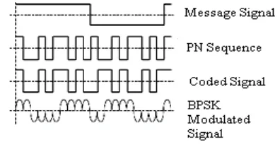
[image:1.595.327.525.342.444.2]implementation and provides better simulation results. The modulation process, i.e., using binary phase shift keying (BPSK) at the output of transmitter is shown in Figure 1 to regenerate the signal strength in its original form after being attenuated by the interferences of several users. Different amount of time delay and attenuation factors provides the multipath diversity, where the diversity order is equal to the number of combined multipath components. The implementation of Transmitter and Receiver side of the circuit were coded using VHDL.
Fig. 1 Modulation using BPSK
2.
DESIGN
The CDMA system consists of a transmitter and receiver and is shown in Figures 2.1 and 2.2. The transmitter receives data from three users, designated as user1, user2 and user3. The information from the three users is mixed by the transmitter in such a way as to generate single output. The single output is also known as channel/channel bandwidth. The Receiver receives the transmitted data from Transmitter and then decodes the signal into original form and extracts one desirable datum. In this system, the transmitter and receiver are assumed to be synchronized using internal clock pulses (delay element) to both transmitter and receiver [3].
User1
User2
User3 Channel User2
Fig. 2.1 Digital CDMA system
User2 Dout
Valid
[image:2.595.356.507.88.232.2]Int. Clk Reset Int. Clk Reset
Fig. 2.2 Digital CDMA system with Clk & Reset
User1
User2
PN Seq. 1
Tx
outValid
User3
PN Seq. 2
Int. Clk Reset
PN Seq. 3
Fig. 2.3 CDMA design with number of inputs
During rising edge of the clock pulse, the TxOut signal starts synchronizing. As the length of the PN code is 127 (i.e., 7 bit PN sequence, having 28-1 possible combinations), so it takes 127 cycles to send 1 bit datum for each user. Delay element made of shift registers and a single multiplexer are shown in Figures 2.4 and 2.5 of synthesized RTL Viewer and Technology Schematics respectively, whose output is equal to 1 [6]. In order to indicate the timing of the PN code starting point, the synchronizing signal SYNCOUT is asserted.
[image:2.595.340.518.279.452.2]In the CDMA design, there is no such SYNCOUT/SYNCIN signal between transmitter and receiver. Thus the receiver shall have a mechanism to find out the starting point of a PN Sequence (generated from feedback shift registers). The transmitter output (TxOut) sends 2 bits signal to the receiver input RxIn. The signal from TxOut to RxIn is actually sum of signals of user1, user2 and user3. The preferred user data has to be extracted from the RxIn signal according to the 2 bits width user inputs (01 for user 1, 10 for user 2, 11 for user3) and any data extracted out of such combinations will be the output of Dout pin [1], [2].
Fig. 2.4 RTL Viewer of delay circuit
Fig
. 2.5 Technology Map Viewer of delay circuit3.
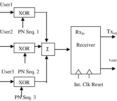
ADVANCED DESIGN OF CDMA
Figures 3.1 and 3.2 depict a configuration in which there are 3 users, each transmitting a different, orthogonal, PN sequence. For each user, the data stream to be transmitted, Usern (where n = 1, 2 and 3) is Exclusive ORed with the spreading code for that user PN Seqn (where n = 1, 2 and 3). The spreading sequence is then modulated for transmission over the wireless channel [8], [13]. Because of multipath effects, the channel generates multiple copies of the signal, each with a different amount of time delay (
1,
2,
3 ) and each with a different attenuation factor (a1, a2, a3). At the receiver end, the combined signal is demodulated. The demodulated chip stream is then fed into multiple correlators, and in each correlator, the received signal is correlated by a spreading code, which is time-aligned with the delay of multipath signal.These signals are then weighted and combined by a maximal ratio combiner, which means that, each signal is weighted by the path gain (attenuation factor) [9]
.
Digital Transm -itter
Digital Receiver
TxOut
Transm-itter
RxIn
Receiver
XOR
XOR
Σ
RxIn
[image:2.595.54.254.324.497.2]Receiver User1
PN Seq. 1
User2
PN Seq. 2
User3
[image:3.595.53.268.62.652.2]
PN Seq. 3
Fig. 3.1 Design of CDMA Transmitter
Received
Signal User1
[image:3.595.46.520.67.666.2]
Fig. 3.2 Design of CDMA Receiver
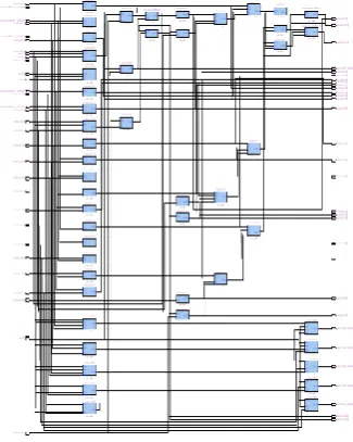
Fig. 3.3 Display RTL Viewer of CDMA Transmitter (User Inputs & PN Sequences) and Channel
[image:3.595.342.514.81.388.2]Let us assume that the receiver is attempting to recover the data of User1. The incoming signal is Exclusive ORed with spreading code of User1 and then demodulated [14]. The effect is to narrow the bandwidth of that portion of the
Fig. 3.4 Display RTL Viewer of CDMA Receiver
Fig. 3.5 Technology Map Viewer of CDMA Transmitter and Receiver
incoming signal corresponding to User1 to the original bandwidth of the unspread signal, which is proportional to the data rate. The remainder of the incoming signal is orthogonal to the spreading code of User1, the unwanted signal energy remains spread over a large bandwidth and the wanted signal is concentrated in a narrow bandwidth. The band pass filter at XOR
XOR
XOR
Σ
M O D U L A T O R
Multi-path
Chan-nels
Σ
Multiple Correlators D
E M O D U L A T
O R
[image:3.595.346.509.425.629.2]correctly. The synthesized RTL Viewer and Technology Schematics are shown in the Figures 3.3, 3.4. and 3.5 respectively.
4.
SIMULATION ENVIRONMENT
Simulation allows us to test a design thoroughly to ensure that it responds correctly in every possible situation before we program or configure a device.
Depending on the type of information needed, one can perform functional or timing simulation with a simulator [6], [7]. Functional simulation tests only the logical operation of a design by simulating the behavior of flattened netlists extracted from the design files, while timing simulation uses a fully compiled netlist containing timing information to test both the logical operation and the best or worst case timing for the design in the target device [10].
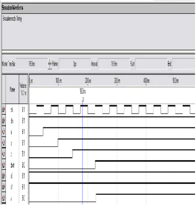
[image:4.595.67.267.327.657.2]The simulator used in this study is the Quartus II simulator that allows circuit design using VHDL. The simulated wave forms of the CDMA (transmitter and receiver) and delay element are shown in the Figure 4.1 and Figure 4.2 respectively. The Quartus II development software provides a complete design environment for system-on-chip (SOC) design.
Fig. 8 Simulation Waveforms of Delay Circuit
5.
FUTURE PROSPECTS
In this paper a technique for CDMA was presented that minimized the interference of several users by sharing the same kind of bandwidth. The higher cost of bandwidth is taken care of by utilization of the bandwidth in an efficient manner. However, the implementation is being considered for a worst case, where the bandwidth is not utilized fully to test for any problems during reception of several users. The sharing of channel increases the overall performance of the system.
Asynchronous logic seems to be winning niches in the digital electronics business within the next few years. It will share circuit boards with clocked chips and integrated circuits with clocked sub circuits. It is likely to become established as a viable alternative technology in many areas and the technology of choice for some.
6.
CONCLUSIONS
This design procedure of CDMA finds applications in multiple access modes to minimize multipath interference by efficient use of bandwidth. The technique used here is a modified version of RAKE receiver and by introducing asynchronism for an increase in speed and reduction in power consumption.
7.
REFERENCES
[1] Duel-Hallen, A., “A Family of Multiuser Decision-Feedback Detectors for Asynchronous Code Division
Multiple Access Channels,” To appear in IEEE Trans. On Commun., Feb. 1995.
[2] Duel-Hallen, A., Holtzman, J., and Zvonar, Z., “Multiuser Detection for CDMA Systems,” IEEE Personal Commun., April 1995, pp. 4-8.
[3] Kumar, V., Srinivas, M. B., “Design of a Digital CDMA Receiver ” VLSI and Embedded Systems Research center: International Institute of Information Technology, Hyderabad India, pp. 587-588.
[4] Mano, M. M., “Digital Design” California State University, Los Angeles 2005, pp. 342-343
[5] Moshavi, S., “Multiuser Detection for DS-CDMA Communications,” IEEE Commun. Mag., Oct. 1996, pp. 12-36.
[6] Pedroni, V. A., “Circuit Design with VHDL,” Prentice Hall of India [PHI] Private Limited 2005, pp. 152.
[7] Prokais, J. G., Salehi, M., Bauch, G., “Contemporary Communication Systems using MATLAB and Simulink,” THOMSON Books/COLE.
[8] Stallings, W., “Wireless Communicatio-ns and Networks,” Pearson Edition Asia 2002, Second Edition, pp. 183-185.
[9] Tantaratana, S., Ahmed, K. M., “Wireless Applications of Spread Spectrum Systems,” IEEE Networking the World 1998.
[10]Tantaratana, W, H., Shanmugan, K. S., Rappaport, T, S., and Kosbar K. L., “Principles of Communication Systems Simulation with Wireless Applications,” Pearson Education 2004.
[11]Varanasi, M. K., and Aazhang, B., “Multistage Detection in Asynchronous Code Division Multiple Access Communications,” IEEE Trans. On Commun., Vol. COM-38, No. 4, April 1990, pp. 509-519.
[12]Verdu, S., “Minimum Probability of Error for Asynchronous Gaussian Multiple Access,” IEEE Trans. on IT., Vol. IT-32, No. 1, Jan. 1986, pp. 85-96.
[13]Viterbi, A. J., “CDMA Principles of Spread-Spectrum Communications”, Reading, Mass.: Addison-Wesley Publishing Company, 1995.