© 2017, IRJET | Impact Factor value: 5.181 | ISO 9001:2008 Certified Journal
| Page 1149
AERO DYNAMIC POWER CONTROL OF PERMANENT MAGNET
SYNCHRONOUS GENERATOR USING FUZZY LOGIC PITCH ANGLE
CONTROLLER
Mr.A.MADHU SUDHAN
1, Mr.TNVLN KUMAR
2, Mr.T.RAVI NKUMAR
31
PG Scholar, M.Tech, Power Electronics, Geethanjali Institute of Science & Technology,
Nellore-524137, Ap, India,
2
Professor, M.Tech, PhD, Geethanjali Institute of Science & Technology, Nellore-524137, AP, India.
3
Assoc.Prof, M.Tech, (PhD), Geethanjali Institute of Science & Technology, Nellore-524137, AP, India.
---****---Abstract:
With an increase in renewable energy resources
plays an important role now-a-days to maintain power quality and increase in electrical power generation to the end user. In this project various control techniques are used to control the aerodynamic power of wind generator using pitch angle control. In conventional methods pitch angle control uses PI and PID controller. In proposed technique hybrid fuzzy logic controller is modelled to control pitch angle of wind generator, here in fuzzy logic method of control turbine output power error and wind turbine speed taken as inputs, FLC produces pitch angle references will remunerates the non-linear sensitivity of wind turbine,. The proposed system is simulated on a 2MW Permanent Magnet Synchronous Generator(PMSG) at wind speed of 12m/sec and 14m/sec simulation can be done in MATLAB or in SIMULINK form. At the end results shows the effectiveness of wind generator which increases efficiency with controlled frequency and voltage magnitude using hybrid fuzzy logic controller.
Index Terms:
Hybrid Fuzzy Logic controller, Pitch angle, Permanent Magnet Synchronous Generator, Wind Turbine.Introduction:
In the past years variable speed wind turbines are pitch adjusting. These turbines consists of two controllers which are cross-coupled each other. At the time of low speed power output will be maximum by adjusting rotor using speed controller. Wind speed at above rated value the power output will be constant using pitch angle control. To control the aerodynamic power of wind turbine several methods are used like Proportional-integral (PI), Proportional Integral Derivative (PID) used to regulate the output power. Drawback of these methods is that the performance has been reduced when operating points are changed. Since the controller design is based on turbine model. On the other, gain scheduling control can be used to control the system non-linearity, here controller gains are adjusted when operating points are changed which provides faster response. The drawback of this method is that controller gains are designed based on turbine model and also it’s difficult to design scheduled functions updating gains at different points.
Figure.1. Block diagram of variable-speed wind turbine
In this proposed model fuzzy logic pitch angle control is used to regulate turbine output power and generator speed at full-load region. Generator output power and rotor speed are taken as inputs instead of wind speed which reduces the cost of anemometer. In addition this control variables power output, generator speed, wind turbine are well maintained to control speed and power output without ripples in output.
Figure.2.Gearless WECS using PMSG.
II.METHODS AND MATERIAL
A. SYSTEM CONFIGURATION
© 2017, IRJET | Impact Factor value: 5.181 | ISO 9001:2008 Certified Journal
| Page 1150
B.WIND TURBINE MODELWind turbine outputs power Tp and wind turbine torque Tw are distinguished by following equations
. Where
V
w is the wind speed, ρ is the air density, R is the radius of the wind turbine,C
p is the wind turbine power coefficient, is the tip-speed ratio, is the angular rotor speed of the wind turbine and, β is the pitch angle.C
p is described by the following equations:C.PMSG MODEL
Essentially, the mass model of PMSG is same as permanent magnet synchronous machine (PMSS).The voltage and torque equations in d-q frame is shown below.
where Vd and Vq are the dq-axis voltages, and are the dq-axis currents, Ra is the stator resistance ,Ld and Lq are the dq-axis inductances, We is the generator rotational speed, K is the permanent magnetic flux, and p is the number of pole pairs. Electromagnetic torque Te should be negative to start generating operation.
2. EXISTING PITCH ANGLE CONTROLLERS:
At high speeds, wind turbine performance can be controlled by pitch angle of the blades. Again these pitch angle blades are kept into normal position by pitch servos which are hydraulic or electrical systems. The pitch angle reference ref is controlled by input values, generator power. The error is sent to PI controller to regulate the power by pitch angle.
A.PI/PID CONTROLLERS
These conventional methods are used to regulate rotor speed and turbine output power. For partial loads ref is set to zero and maximum power point tracking (MPPT) method is utilised. So that energy conversion coefficient is maximised at partial loads.Where as in full-load region, the pitch controller is activated to regulate the generator output power. For designing PI/PID controllers
non-linear dynamics of wind turbine is linearized at particular operating point at which generator and turbine torques were same. In this method when operating points are changed PI gains should be adjusted to maintain the system dynamic response and stability.
B.PI CONTROLLER WITH GAIN SCHEDULING
This method is used to control nonlinearity in PI controller. This gain scheduling is used to remunerate for the changes in sensitivity of aerodynamic torque to pitch angle.
C.FUZZY LOGIC CONTROL
In this the controller can be designed based on human experience through a set of rules has been used to control pitch angle. The wind speed and generator output power taken as control inputs of FLC.The advantage of this method is that the parameter of wind turbine system doesn’t need to be known accurately. Nevertheless this method requires wind speed information.
3. Proposed Hybrid Fuzzy Logic Pitch Angle Controller
The proposed pitch angle control block diagram shown below fig.3.At partial load the power reference Pref of wind turbine can be determined by MPPT control strategy.
Where
and the maximum power coefficient Cp max corresponds to the optimal tip-speed ratio opt, with a zero-pitch angle.In the high-wind-speed region, Pref the selected as the rated power of wind turbines.To find pitch angle reference FLC takes inputs and execute fuzzy rules and convert into output value is called defuzzyfication.
The error in the generator power P, the variation of
the power error
,
and the rotational speed are
considered as the controller inputs.
© 2017, IRJET | Impact Factor value: 5.181 | ISO 9001:2008 Certified Journal
| Page 1151
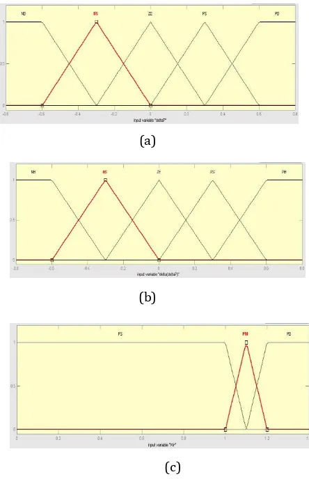
The pitch angle reference is considered as a controller output. To design the fuzzy sets of the inputs and output, the triangular membership functions with the overlap are used, which are illustrated in Fig. 5. The linguistic variables are represented by Negative Big (NB), Negative Medium Big (NMB), Negative Medium (NM), Negative Small (NS), Zero (ZE), Positive Small (PS), Positive Medium (PM), Positive Medium Big (PMB), and Positive Big (PB). The control rules are derived from the experience and knowledge on the control system. The fuzzy mapping of the input variables to the output is expressed by the following rules:
The sugeno model of inference is applied to
this system. Each rule is weighted by the weighting
factor of the rule, which is obtained from the
minimum operation as
Where
and
are the
triangular membership functions of the
.
The output of weighted average is the variation of
pitch angle reference shown below
[image:3.595.327.549.80.424.2]Table 1.Wind Turbine parameters for simulation
Table 2. PMSG parameters for simulation
(a)
(b)
(c)
Fig.4. Membership Functions of FLC. (a) Error of output generator power, (b) Variation of power error, (c)
Rotational Speed, (d) Pitch angle reference
[image:3.595.50.265.449.624.2]4.SIMULATION DIAGRAM
Fig.5.Simulation Diagram
5. RESULTS
Simulation Results
[image:3.595.310.554.502.685.2]© 2017, IRJET | Impact Factor value: 5.181 | ISO 9001:2008 Certified Journal
| Page 1152
[image:4.595.311.554.88.208.2]investigate the performance of the PI controllers and the Hybrid FLC at the different operating point, the rated wind speed which classifies the partial and full-load regions is set as 14 m/s, differently from the previous case of 12 m/s. Fig. 6 shows the results of the pitch control for the PI controller and the proposed fuzzy controller, at the rated wind speed of 14 m/s. The gain parameters for both the PI/PID controllers and the membership function of the fuzzy logic control are the same as those of the prior case. All of the pitch angle control methods can limit the generator power and rotor speed to their rated values. However, the pitch angle control employing the proposed hybrid fuzzy control method gives better performance than those of the PI control. The results of generator output power, rotor speed, and mechanical torque, respectively, where with the same controller. Below results shows fuzzy logic controller at 14m/sec wind speed.
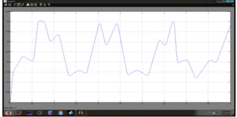
Fig.6 Wind Speed at 14m/sec
Fig.7.Generator Powers
Fig.8.Rotor speed
[image:4.595.319.546.240.372.2]Fig.9.Power Conversion Coefficient
Fig.10.Mechanical Torque
Fig.11.Pitch angle reference
[image:4.595.35.290.309.449.2]Fuzzy Logic Controller at 12m/sec wind speed
[image:4.595.311.553.586.725.2]© 2017, IRJET | Impact Factor value: 5.181 | ISO 9001:2008 Certified Journal
| Page 1153
Fig.13.Generator Powers
Fig.14.Rotor speed
Fig.15.Mechanical Torque
Fig.16.Power Conversion Coefficient
Fig.17.Pitch angle reference
SIMULATION RESULTS WITH PI CONTROLLER
Wind Speed at 12m/sec
Fig.18.Wind speed at 12m/sec
Fig.19.Gnerator Power
Fig.20.Mechanical torques
© 2017, IRJET | Impact Factor value: 5.181 | ISO 9001:2008 Certified Journal
| Page 1154
Fig.22.Pitch angle
Fig23.rotor speed
Wind speed at 14m/sec
Fig.24.Wind speed at 14m/sec
Fig.25.Rotor speed
Fig.26.Power conversion coefficients
Fig.27.Pitch angle
6. CONCLUSION
At the end simulation done on PMSG wind generator using fuzzy logic controller. Here generator output power and wind speed are taken as fuzzy inputs. Fuzzy logic pitch angle controller can regulate the generator output power and wind speed at high speed regions. It is more accurate than conventional PI/PID controller. In this control scheme derived from small signal analysis. It improves the performance and efficiency of wind generator under high speed and reduces faults due to pitch angle variations.
REFERENCES
[1] N. P. W. Strachan and D. Jovcic, "Improving wind power quality using an integrated wind energy conversion and storage system (WECSS)," in Proc. IEEE Power Energy Soc. Gen. Meeting, Jul. 2008
[2] S. Roy, "Power output by active pitch-regulated wind turbine in presence of short duration wind variations," IEEE Trans. Energy Convers., vol. 28, no. 4, pp. 1018–1025, Dec. 2013.
[3] A. O. Ibrahim, T. H. Nguyen, D.-C. Lee, and S.-C. Kim, "A fault ridethrough technique of DFIG wind turbine systems using dynamic voltage restorers," IEEE Trans. Energy Convers., Sep. 2011.
© 2017, IRJET | Impact Factor value: 5.181 | ISO 9001:2008 Certified Journal
| Page 1155
[5] J. Zhang, M. Cheng, Z. Chen, and X. Fu, "Pitch angle control for variable speed wind turbines," in Proc. 3rd Int. Conf. DRPT, 2008, pp. 2691–2696.
BIOGRAPHIES
A.Madhu Sudhan, received B.Tech from Narayana Engineering College, Gudur, AP,India. Currently pursuing M.Tech at Geethanjali Institute of Science & Technology, Nellore, AP,India. The research interest includes Electrical power Control and Energy Efficiency.
Mr.TNVLN Kumar,M.Tech,PhD,Professor & Head of the EEE Department at Geethanjali Institute of Science Technology,Nellore,AP,India.
Mr .T. Ravi Kumar, M.Tech, (PhD)