© 2017, IRJET | Impact Factor value: 5.181 | ISO 9001:2008 Certified Journal | Page 1988
Mutual Coupling Reduction of Micro strip antenna array by using the
Electromagnetic Band Gap structures
A.Rajasekhar
1, K.Vara prasad
21
M.tech student, Dept. of electronics and communication engineering, VR Siddhartha Engineering College, Andhra
Pradesh, India.
2
Assistant professor ,Dept. of electronics and communication engineering, VR Siddhartha Engineering College,
Andhra Pradesh , India.
---***---Abstract -
Electromagnetic band gap structures havebeen proven to be a best way to reduce the surface waves. Various types of EBG structures have been proposed and investigated in recent years. One of the most popular EBG is mushroom like EBG. In this paper a miniaturized patch antenna array is designed which is resonant at 5.8 GHz WLAN Band. To reduce the mutual coupling, the novel mushroom like EBG array configuration is proposed and is placed between the antenna elements to reduce the mutual coupling. The measured result show a reduction in the mutual coupling by 18 dB, obtained for elements with EBG structure. High Frequency Structure Simulation Software (HFSS) is used to plot the results.
Key Words: Electromagnetic band gap (EBG), Antenna
array, Mutual coupling, WLAN.
1. INTRODUCTION
In Recent years various methods were developed and employed to reduce the mutual coupling between the micro strip patch antenna arrays and this has become a hot topic [2]. Micro strip patch antennas are very attractive by their compact design, low profile and cost effective for wireless communication system. For high gain and high diversity multiple antennas are used called as an antenna array. The main problem with the antenna array is mutual coupling. When the isolation between the antenna elements is less than the λ/2 then the surface waves are excited [4] over the surface of antenna which initiate the mutual coupling between the elements of antenna array as a result loss of which low power is observed and there is effect on gain and directivity also. In order to reduce the mutual coupling effect between the antenna elements, the isolation between the elements should be greater than λ/2. But due to this, the size of the antenna increases. The design should be compact and mutual coupling should be minimized [1].
To reduce the problem of mutual coupling different ways like cavity backing, substrate removal [3] and Defected Ground Structure (DGS) [5] are used. These approaches were related with fabrication difficulties since the cavity making with PEC wall or the partial substrate removal
required detailed micro-machining techniques and there are chances of performance degradation. The DGS increases back radiation [6] from an antenna and it can mitigate but it is less when compare with the cavity backing case. Among these strategies, the EBG structures are observed to be best technique.
Electromagnetic Band Gap (EBG) structures with their periodic-like structures will produce some band gap features. The features of an EBG are revealed in ways: The surface wave is suppressed as it travels along the structure in specified frequency bands in a guided direction and forbidding the propagation of EM waves into certain frequency bands. The elimination of surface waves will helps to improve an antenna performance by increasing the antenna gain and reducing the radiation.
This paper mainly focus on a method to reduce mutual coupling between micro strip antenna array elements is proposed by using mushroom like EBG structure. By using the proposed EBG structure reduction in mutual coupling level by 18dB is achieved and the size of the antenna is decreased.
2. Antenna design
2.1
Initial Antenna Design
© 2017, IRJET | Impact Factor value: 5.181 | ISO 9001:2008 Certified Journal | Page 1989
Figure 1:- Initial patch antenna array without EBGstructures.
[image:2.595.41.285.339.527.2]Chart 1:- simulated S-parameter return loss of antenna array without EBG structures.
Table 1:- Design parameters.
Lengt
hs Values (mm) ngtLe hs
Values (mm)
a 68 i 3.3
b 40 p 7.7
c 6.3 g 0.7
d 30 L 11.4
E 2.4 w 14
f 2 r 1
R 1.2 h 1.6
X 48 Y 40
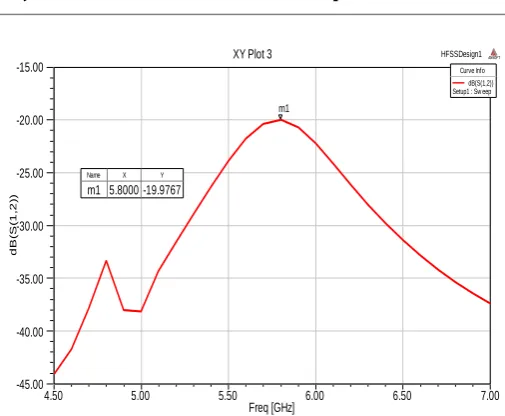
Chart 2:-Transmission coefficient of antenna array without EBG structures.
2.1.2 Mutual coupling comparison
Mutual coupling level of the patch antenna is investigated by varying the distance between the patch elements in the antenna array at resonant frequency. The transmission co-efficient results shown in figure-3 of the antenna array are plotted with different distances between patches. The above results as in table-2 show that the mutual coupling level is increased with decrease of the distance between the patches.
Table 2:- Mutual coupling comparison.
Chart -3: Mutual coupling comparison of antenna array without EBG structures with different distance between the antenna elements of 35mm, 30mm, and
25m.
4.50 5.00 5.50 6.00 6.50 7.00
Freq [GHz] -25.00 -20.00 -15.00 -10.00 -5.00 0.00 d B (S (1 ,1 )) HFSSDesign1
XY Plot 1 ANSOFT
m1
Curve Info dB(S(1,1)) Setup1 : Sw eep
Name X Y
m1 5.8000 -24.7111
4.50 5.00 5.50 6.00 6.50 7.00
Freq [GHz] -45.00 -40.00 -35.00 -30.00 -25.00 -20.00 -15.00 d B (S (1 ,2 )) HFSSDesign1
XY Plot 3 ANSOFT
m1
Curve Info dB(S(1,2)) Setup1 : Sw eep
Name X Y m1 5.8000 -19.9767
4.50 5.00 5.50 6.00 6.50 7.00
Freq [GHz] -50.00 -45.00 -40.00 -35.00 -30.00 -25.00 -20.00 -15.00 S 1 2 d B HFSSDesign1 30mm ANSOFT 30mm 35mm 25mm Curve Info dB(S(1,2)) Setup1 : Sw eep dB(S(1,2))_1 Imported
dB(S(1,2))_2 Imported Name X Y
30mm 5.8000 -19.9767 35mm 5.8000 -21.3685 25mm 5.8000 -18.7174
Distance (mm) Frequency S12 level (dB)
25mm 5.8 GHZ -18.71
30mm 5.8 GHz -19.97
[image:2.595.307.559.465.722.2]© 2017, IRJET | Impact Factor value: 5.181 | ISO 9001:2008 Certified Journal | Page 1990
2.2
EBG structure configuration
EBG structures have a significant property to suppress the surface wave’s propagation and the in-phase reflection co-efficient .This structure shows a discrete stop band for surface wave propagation. Parameters influencing the properties of EBG structure like stop band and pass band, depend on patch width, gap width, substrate thickness and substrate permittivity.
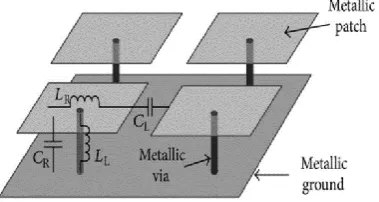
To investigate unique features like band gap and pass band of EBG structure a lumped element model is the simplest way. The electromagnetic properties of the EBG unit cell can be described using Lumped-circuit elements like capacitors and inductors shown in figure 4. In the frequency range where the surface impedance is very high the equivalent LC circuit acts as a two dimensional electric filter to block the flow of the surface waves. The inductor L, results from the current flowing along adjacent patches through narrow gap effect between the patches.
[image:3.595.324.548.69.269.2]The novel mushroom like EBG proposed which consists of four parts: ground plane, a dielectric substrate, metallic patches, and connecting vias. The proposed structure as shown in figure-4 is placed on the dielectric substrate FR-4 with dimensions of 6.3mm X 6.3 mm.
Figure 4:- Lumped element model of EBG structure.
One of the main features of the EBG structure is suppression of surface waves in a specified frequency band. The mushroom like EBG structure is fabricated between the antenna array elements to mitigate the surface waves.
[image:3.595.307.557.288.487.2]The proposed antenna array as shown in fig 6 is designed on the FR4 substrate with relative permittivity of 4.4, thickness of 1.6mm and a loss tangent of 0.02. The dimensions of antenna are 48mm X 40 mm. The distance between the patch antenna elements is d=30mm. A 3X2 mushroom like EBG structure array is inserted between the patch elements of array. The proposed antenna array is simulated in Ansoft HFSS.
[image:3.595.67.257.421.522.2]Figure 5:- Unit cell of mushroom-like EBG structure.
Figure 6:- Patch antenna array with EBG structures.
© 2017, IRJET | Impact Factor value: 5.181 | ISO 9001:2008 Certified Journal | Page 1991
Chart 4:- simulated S11 of a patch antenna with andwithout EBG structures.
Chart 5:- simulated S12 of a patch antenna array with and without EBG structures.
From figure-9 the simulated current distribution can noticed at 5.8GHz. The EBG structure reduces the surface wave’s excitation so the current density on the antenna surface also reduced. The simulated results conform the suppression of the surface current by the EBG structure, less effect on second patch due to the first element which dictates the reduction in mutual coupling and improvement in the isolation between the array elements.
(a)
[image:4.595.39.287.352.554.2](b)
Figure 7:- Surface current distribution (a) with and (b) without EBG structure.
The simulated radiation pattern of the patch antenna array at 5.8GHz plotted in figure-7 there is no change in the shape of the patterns.
© 2017, IRJET | Impact Factor value: 5.181 | ISO 9001:2008 Certified Journal | Page 1992
(b)Chart 6:- Radiation pattern of the array antenna at 5.8GHz with EBG (red) and without EBG (blue) (a)
E-plane (b) H-E-plane.
3. Comparison of EBG structure method with
other approaches
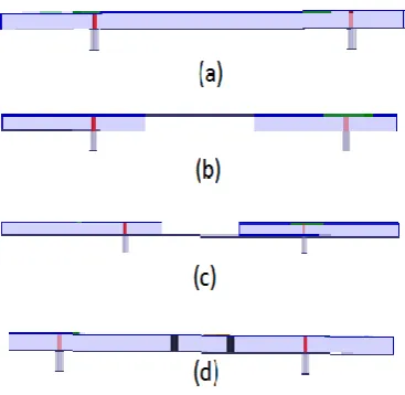
[image:5.595.311.557.284.481.2]EBG structure method as shown in figure-8 is compared with other structures used to reduce the mutual coupling like,
Figure 8:- different approaches, (a) Normal, (b) Back cavity, (c)Substrate removal, (d) EBG structure. In this comparison of the antenna size, substrate properties and distance between patches are same. A 13.3mm width substrate is removed between the patch antennas. This width is chosen to be the same as the total width of two rows of EBG patches.
1. Substrate removal method 2. Cavity back method
3. Normal without EBG method
Table 3:- comparison of EBG structure method with other approaches
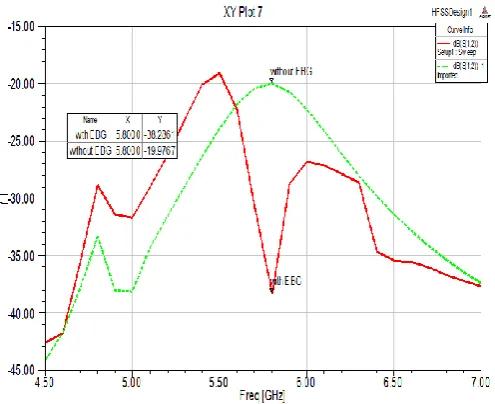
The comparison shows in figure-9, table-3 that EBG structure is effective method to reduce the mutual coupling.
Chart 7:- comparison of simulated S12 of EBG with other approaches.
4. CONCLUSIONS
In this paper, a mushroom like EBG structure is employed to design antenna array to minimize the mutual coupling in between the patch antenna array .The proposed antenna is simulated in Ansoft HFSS. The simulated results show that the mutual coupling is reduced by 18dB in antenna which is operating at 5.8GHz WLAN Band and the EBG structure method is also compared with other approaches.
EFERENCES
[1]. Mak, A. C., Rowell, C. R., & Murch, R. D. (2008). Isolation enhancement between two closely packed antennas. IEEE Transactions on Antennas and Propagation, 56(11), 3411-3419.
[2]. Elsewe, M. M. (2016). Design guidelines, scan behavior and characteristic mode analysis for a class of ultra-wideband microstrip patch antennas (Doctoral dissertation, University of Missouri-Kansas City).
4.50 5.00 5.50 6.00 6.50 7.00
Freq [GHz] -50.00
-45.00 -40.00 -35.00 -30.00 -25.00 -20.00 -15.00
S
1
2
d
B
HFSSDesign1
XY Plot 4 ANSOFT
substrate removal
w ith EBG back cavity w ithout EBG
Curve Info dB(S(1,2)) Setup1 : Sw eep w ith EBG Imported
dB(S(1,2))_1 Imported
w ithout EBG Imported
Name X Y
substrate removal 5.8000 -20.5462 with EBG 5.8000 -35.4568 back cavity 5.8000 -21.2179 without EBG 5.8000 -19.9898
approaches Frequency S12 level (dB)
Normal 5.8 GHZ -19
Substrate
removal 5.8 GHz -20
Back cavity 5.8GHz -21
[image:5.595.67.251.438.617.2]© 2017, IRJET | Impact Factor value: 5.181 | ISO 9001:2008 Certified Journal | Page 1993
[3]. Yang, F., & Rahmat-Samii, Y. (2003). Microstripantennas integrated with electromagnetic band-gap (EBG) structures: A low mutual coupling design for array applications. IEEE transactions on antennas and propagation, 51(10), 2936-2946.
[4]. Rajo-Iglesias, E., Quevedo-Teruel, O., & Inclan-Sanchez, L. (2008). Mutual coupling reduction in patch antenna arrays by using a planar EBG structure and a multilayer dielectric substrate. IEEE Transactions on Antennas and Propagation, 56(6), 1648-1655.
[5]. Xiao, S., Tang, M. C., Bai, Y. Y., Gao, S., & Wang, B. Z. (2011). Mutual coupling suppression in microstrip array using defected ground structure. IET Microwaves, Antennas & Propagation, 5(12), 1488-1494.