http://dx.doi.org/10.4236/jmp.2015.62018
Electrical Noise, Brownian Motion and the
Arrow of Time
Jose-Ignacio Izpura
Department of Aerospace Systems, Air Transport and Airports, GMME-CEMDATIC Research Group, Universidad Politécnica de Madrid (UPM), Madrid, Spain
Email: [email protected]
Received 15 September2014; accepted 13February 2015; published 25February 2015
Copyright © 2015 by author and Scientific Research Publishing Inc.
This work is licensed under the Creative Commons Attribution International License (CC BY).
http://creativecommons.org/licenses/by/4.0/
Abstract
The origin of the Johnson noise of resistors is reviewed by a new model fitting in the Fluctuation- Dissipation framework and compared with the velocity noise in Brownian motion. This new model handling both fluctuations as well as dissipations of electrical energy in the Complex Admittance of any resistor excels current model based on the dissipation in their conductance. From the two orthogonal currents associated to a sinusoidal voltage in an electrical admittance, the new model that also considers the discreteness of the electrical charge shows a Cause-Effect dynamics for electrical noise. After a brief look at systems considered as energy-conserving and deterministic on the microscale that are dissipative and unpredictable on the macroscale, the arrow of time is discussed from the noise viewpoint.
Keywords
Electrical Noise, Fluctuation-Dissipation, Cause-Effect, Complex Admittance, The Arrow of Time
1. Introduction
This paper improves a recent work [1] and a new model for electrical noise [2] that we will use to consider Brownian and Johnson noises under the Fluctuation-Dissipation framework of [3]. The improvement we will add in Section 2 is a relativistic remark on the measurement of a voltage difference between two points (termi-nals) separated in space. This justifies the random series in time of uncorrelated current pulses leading to the voltage noise called Johnson noise in resistors or kT C noise in capacitors. This discrete model and the veloc-ity noise of a particle under Brownian motion are compared in Section 3 focusing on the collision time δtc
measured noise.
2. Fluctuations and Dissipations of Electrical Energy in Resistors
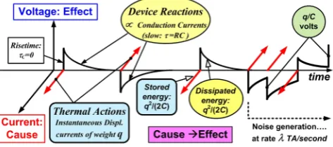
Figure 1 summarizes a new model for electrical noise in resistors [2] and shows the admittance where it can occur. The capacitance C that exists between the terminals of any two-terminal device (2TD) is the key element to have fluctuations of electrical energy and thus, electrical noise in these devices. Now let us add the discrete-ness of the electric charge. We mean the electronic charge q≈ −1.6 10× −19 C
(Coulombs) passing as a whole between the terminals of the resistor each time a noise pulse occurs randomly in time (50% in each sense on av-erage). Each of these pulses where an electron passes between terminals is an impulse-like displacement current of weight q in C, thus a fluctuation of electric field and energy in C. As we wrote in [4], neither media nor mate-rial exist with null dielectric constant ε =0. This guarantees a non-null C≠0 in any 2TD. Applying thermal Equipartition in C we deduced the new model by considering that in Thermal Equilibrium (TE) it would give the same numerical results given by the noise model in use, where resistance R is taken as the source of electrical noise. Hence, the novelty of [2] is that capacitance C is the source of electrical noise of the resistor and not its R
nor its conductance G=1 R. This allows solving problems out of TE that current model is unable to handle [2] [4]-[7].
Each passage of a single electron between plates of C, which means a sudden fluctuation ∆E of electric field between the terminals of a resistor, was called a Thermal Action (TA) [2]. The energy associated to a TA be-comes quantized by the device itself because in a discharged C this displacement of a charge −q between ter-minals sets this fluctuation of electrical energy:
2
2 q U
C
∆ = (1)
For C=1 pF we have ∆ ≈U 1.3 10× −26 J whereas the thermal energy at T =300 K is: kT ≈ ×4 10−21 J for k being the Boltzmann constant. From ∆ =U 0.00003kT we concluded that the passage of a single electron between terminals of resistors was a likely event at room T and even at cryogenic ones. This led us to propose that random TAs were the source of Johnson noise in resistors and kT C noise in boundary capacitors (Boundary Space Charge Regions BSCR) whose back gating effect gives the ubiquitous resistance noise with 1/f
spectrum of Solid-State devices [4]. The set of electromagnetic interactions giving rise to this series of TAs in a 2TD would form its thermal contact with the surrounding universe and would sustain in time the voltage noise we observe in devices like resistors and capacitors that share the admittance ofFigure 1[2] [4] [5].
Because the most likely situation when a TA occurs is a discharged C (the expected value of Johnson noise is null) we will use Equation (1) as a “useful mean value” for the energy involved in TAs. The case with a small charge in C due to preceding TAs falls out of the scope of this preliminary paper. Each sudden TA setting a voltage step of ∆ =V q C volts in C initiates a Device Reaction (DR) to relax the energy unbalance stored in
[image:2.595.204.423.590.695.2]C by the TA [2]. This relaxation is the discharge of C through the resistance R of the resistor. Let us call Dissi-pation to this relaxation process taking place in TE, where the voltage in C is very small. This way the new model not only fits into the Fluctuation-Dissipation framework of [3], but also agrees with the word “Irreversi-bility” of its title due to its Cause → Effect dynamics where a fluctuation of electromagnetic energy (Cause) precedes to a subsequent dissipation of electrical energy (Effect).
This ordainment (TA first) → (DR next) can exist in a Complex Admittance but not in the real Resistance that uses current noise model for resistors. Considering TAs (reactive currents) and DRs (conduction currents) under the same voltage noise we have two orthogonal powers. The first one is reactive power PC entering the resistor
“by” C and the second is active power PR leaving it “by” R (see [2] for details). From the well-known kT C
noise of a capacitor at temperature T the active power PR will be the mean square voltage noise kT C V2
di-vided by R. This voltage is the measurable effect we observe in the resistor (e.g. its Johnson noise) whereas the shot noise represented by the noise generator of spectral density 4kT/R A2/Hz (Nyquist noise) or the charge noise of power 4kT RC s2 in C [2], cannot be measured directly because it is a charge displacement noise that a voltmeter cannot sense until it has produced a measurable voltage in C.Figure2 shows this Cause-Effect dynamics in orthogonal domains linked by a time-related process in C that we will deal with in Section 4.
Using Equation (1) as explained, an average rate λ of TA-DR pairs can be estimated for a resistor of resis-tance R in TE at temperature T. Since the reactive power PC that enters this device on average will be λ times
the energy ∆U set by each TA in C and PC must equate in TE the PR leaving the resistor due to its R, we have [2]:
2
2
1 2
2
R C
kT q kT
P P
C R λ C λ q R
= × = = × ⇒ = (2)
Thus, a resistor in TE would collect an average power PC by its C acting as a receiving antenna for TAs and
would release an equal amount (on average) of electrical power converted into heat by its R. Note this picture for resistance R as a random set of chances to convert electrical energy into another form: usually phonons, but it could be photons as well (think of a radiation resistance). This discrete nature of R, or better said: of the elec-trical noise itself, allows a direct explanation for the phase noise of electronic oscillators (their line broadening for example) as due to the λ TAs associated with the resistance R of their resonators by Equation (2) [6] [7].
The sum in power of TA’s done in Equation (2) (e.g. PC = × ∆λ U) requires to show that TAs are
monoelec-tronic events uncorrelated in time. To discard the sum in voltage of two or more overlapping TA’s (e.g. the si-multaneous passage of two or more electrons through C) we will say that it would lead to packets of charge −2q, −3q, etc., not observed in experiments. Hence let us show how these TAs can be fully random in time despite their huge rate λ expected from Equation (2) that gives λ≈ ×3 1014 TA/second for a 1 kΩ resistor at room T. This would explain why Johnson noise seems continuous up to frequencies well beyond microwave ones, but this huge λ suggests that TAs would be prone to overlap in time, except if the transit time δtc of the electron
passing in each TA was null for the noise meter as assumed in [1] [2] without proof. Let us prove here that this is the case, thus giving a null rise time δtc=0 for each voltage pulse decaying with time constant τ =RC in
Figure2.
[image:3.595.195.432.579.684.2]If a TA is a small fluctuation of electric field between the terminals of the 2TD, thus a time-varying electric field, then it becomes a fluctuation of electromagnetic field between two points of the resistor (its terminals) at distance d in space. As Einstein showed in 1905, an electromagnetic signal departing midway two points sepa-rated in space by a distance d defines simultaneityat these two points. Added to this, the relativity principle he extended to all physical measurements means that noise ones cannot detect absolute motion in space. This means that each TA will be born “midway” the two terminals of the resistor. Otherwise the sense and the speed
of the absolute motion of the resistor would affect the electrical noise measured between terminals. Thus, the ar-rival of a TA in the terminals as an electrical voltage will define simultaneity for two observers measuring elec-trical voltage at these terminals. This way, each TA becomes an instantaneous event
(
δtc =0)
for the noise meter that measures (and subtracts) electrical voltages appearing simultaneously on these terminals.This means that the noise pulses ofFigure2 have null rise time δtc =0, a feature allowing the passage of electrons between terminals independently of one another. Thus, TAs are uncorrelated in time as we have sup-posed and must be added in power to obtain the reactive power PC. This δtc =0 also prevents any time
over-lapping of TAs (displacement currents) with their subsequent DRs (conduction currents) as we would expect from these currents being orthogonal in sinusoidal regime. This expresses in time domain the orthogonal nature of these two types of currents being in quadrature for any sinusoidal voltage synthesizing Johnson noise in the circuit of Figure1. This noise model just described is not far from the “thermal agitation of electric charge” written in 1928 by J. B. Johnson [8] and H. Nyquist [9] in the titles of their pioneering works.
3. Electrical Noise, Brownian Motion and the Fluctuation-Dissipation Theorem
The complex impedance used in [3] to deal with electrical noise under the Fluctuation-Dissipation framework is close to the admittance ofFigure1. We must say, however, that although this circuit has a resistance and a noise generator similar to those appearing in the model used today for the electrical noise of resistors, the new model
[2] is by far more general because it not only includes C, but also generalizes R to include any ohmic and non- ohmic (differential) resistance defining the conductance G
( )
ω =1 R( )
ω of the admittance( )
( )
( )
Y jω =G ω + jB ω of the 2TD at hand. This Y jω
( )
leads to consider the noise voltage v t( )
as the time-varying signal that links noise currents through G( )
ω with noise currents through the susceptance( )
B ω =ωC at each frequency f =ω
( )
2π in the sinusoidal regime that underlies the Fourier synthesis of Johnson noise.Considering a voltage noise v t
( )
as synthesized from sinusoidal terms vn( )
t , each noise current iP( )
t through the conductance G=1 R will be a sinusoidal current given by: iP( )
t = ×G vn( )
t (seeFigure1), thus in-phase with vn( )
t . This is a conduction current term associated to vn( )
t in sinusoidal regime. On the other hand, the noise current term iQ( )
t associated with vn( )
t will be this sinusoidal current: iQ( )
t = jB v× n( )
t , thus a current term in-quadrature with vn( )
t . From the positive B=ωC offered by C, any current iQ( )
t will have +90˚ phase advance respect to its related vn( )
t . Hence, the time integral of displacement currents like( )
Q
i t in C will have equal phase than vn
( )
t , thus suggesting that iQ( )
t is the Cause that integrated in time by C, builds the Effect vn( )
t that synthesizes the Johnson noise of resistors or the kT C noise observed in capacitors. After this brief introduction in frequency domain, let us work in time domain to link this noise volt-age v t( )
with the velocity noise in Brownian motion.To study the voltage noise v t
( )
in the admittance ofFigure1 we will replace its Nyquist noise of 4kT RA2/Hz by a random current iNy
( )
t with zero mean value as shown inFigure3, where Kirchoff’s law leads to:( )
( )
( )
d
d Ny
v t
C Gv t i t
t
× = − + (3)
Equation (3) states that any band-limited iNy
( )
t will create both a displacement current in C and a conduc-tion current in R because to have only a pure displacement current in C, we need a δ-like current iNy( )
t of in-finite bandwidth (BW → ∞) or null duration(
δtc →0)
. In this case, Equation (3) integrated in time during0
c
t
δ → gives:
built
q v
C
[image:4.595.231.397.606.680.2]∆ = (4)
where the weight q (thus a charge) of the δ-like current iNy
( )
t has created a voltage step ∆vbuilt =q C in C. Equations (3) and (4) were obtained in [1] and arrived at this point, we wrote: “Thus, a pure Fluctuation of energy is not possible in resistors because their iNy( )
t is band-limited as Nyquist showed by an upper limit for their 4kT R A2/Hz density due to Quantum Mechanical reasons [9]. Although very pure Fluctuations of en-ergy result in this circuit for iNy( )
t currents with short δtc, they always have a non null Dissipation due to theconduction current during the non null δtc elapsed. To say it bluntly: an electron leaving one plate with a
ki-netic energy of q2
( )
2C Joules exactly in a discharged C, is unable to create ∆vbuilt =q C V in C because part of its q2( )
2C J is dissipated during its non null transit time δtc. Thus, no paradox exists if we find thissystem dissipative in the macroscale with a huge amount of such transits giving rise to a noticeable dissipation of energy. Assuming, however, that these passages of single electrons between plates are energy-conserving events because the term Gvn
( )
t has no time to dissipate a noticeable amount of energy during each short tran-sit time δtc, we would find a paradox due to this wrong assumption…”For δtc=0 these sentences must be reviewed as we are going to do. Let us say, however, that they were written with these phrases in mind: “one of the great paradoxes of statistical mechanics is how a system can be energy conserving and deterministic on the (molecular) microscale, and yet dissipative and unpredictable/ran- dom on the macroscale. The paradox is resolved by recognizing that both the dissipation and the random fluc-tuations are associated with incomplete information about the state of the system” [10]. Let us say too that we also were considering the academic viewpoint given in [10] on the Fluctuation-Dissipation Theorem where it was nicely explained by a mechanical example using the Brownian motion of a large particle of mass M through a sea of small particles having random motions. In this example, a short but non null collision time δtc was
used together with energy conserving collisions. Therefore, we argued in [1] that the aforesaid paradox appeared because the premise “energy-conserving collisions” was wrong. For δtc ≠0 there is no way to avoid some Dissipation during the interaction time δtc and thus, the proposed energy-conserving collisions do not exist in
the example of [10].
This solves the paradox in Brownian motion but the null δtc =0 found for TAs could translate this paradox to the case of Johnson noise. Before showing how this possible paradox is solved, let us consider the evolution of our model for electrons giving rise to TAs. Our sentence: “an electron leaving one plate with a kinetic energy of q2
( )
2C Joules…” shows the “corpuscular” model we used at this time (based on the carrier drift model for conduction currents). We had to abandon this model, however, replacing it by one agreeing with the wave-based model giving rise to δtc =0. The new model for conduction currents that distinguishes dissipation in TE from Joule effect in the resistor put out of TE by an applied voltage can be seen in [11].To resume our reasoning, let us recall the formal analogy between Johnson and Brownian noises that use to be studied by the Langevin equation. As we have written below Equation (3), a δ-like current iNy
( )
t of infinite bandwidth (BW → ∞) or null duration(
δtc →0)
prevents Dissipation while Fluctuation occurs in electrical noise. Nevertheless, in the Brownian motion of a large particle of mass M through a sea of small particles hav-ing random motions this δtc →0 condition looks unreal because it leads to an infinite force (e.g. to an unac-ceptable mechanical power) in each collision. Following [10] the small particles exert, through collisions, a random force F t( )
on the large one whose velocity at time t relative to the mean motion of the small ones is( )
v t . The mean drag force on the large particle is proportional to v t
( )
through the friction factor ξ and the fluctuating random component is proportional, with a coefficient of proportionality κ, to the so called statisti-cal white noise Ξ( )
t . Copying Equation (1) of [10] to have the equation of motion of the large particle, we have:( )
( )
( )
d Ξ d v tM v t t
t ξ κ
× = − + (5)
Equation (5) formally equal to Equation (3) suggests that the role of inertial mass M in Brownian motion would be similar to the role of electrical capacitance C in electrical noise. Nevertheless, taking C = 0 to study electrical noise in resistors would be rule whereas taking a large particle of mass M = 0 to study its Brownian motion would be the exception (to our knowledge). Leaving aside this “curious situation” let us resume the reasoning of
[10] where it is written: “The aim of the fluctuation-dissipation theorem is to relate ξ to the statistics of
( )
tκΞ ”. Using a white noise process for Ξ
( )
t , the mean square fluctuating force 20
F obtained in [10] was:
( )
(
)
2 2 2 0 2 Ξ cF t kT t
ξ κ
δ
where δtc is the contact time during a collision. Below this result we read in [10]: “This is the required
state-ment of the fluctuation-dissipation theorem, relating as it does the mean square fluctuating force to the friction factor”. From the analogy between Johnson and Brownian noise, the electrical counterpart of Equation (6) we found in [1] was:
( )
(
( )
)
22 2 Ξ 2 4 1 4
2
Ny Q
c c
kT kT kT
i f
t R t
t
R
t ξ
κ
δ δ
= = = × ≈ × (7)
where we had to approximate the mean square i2Ny
( )
t by the product of the flat density Si( )
f =4kT R A2/Hz by an upper frequency fQ (Hz) derived from [9] by the expression kT≈hfQ where h is the Plankcon-stant. This fQ is required to keep finite
( )
2
Ny
i t and it would reflect the frequency region where the Nyquist noise Si
( )
f drops due to Quantum reasons (e.g. fQ ≈6 THz at room T). This fQ that limits the electricalpower in the resistor translates by Equation (7) into an interaction time ∆tTA that we have considered as a time interval between TAs or perhaps a time interval to prepare each TA that would be δtc≈0.08 ps at room T.
Given the null duration δtc =0 of each TA in the new model we should give a reason to have a minimum time interval ∆tTA between TAs in a resistor in TE at temperature T. This reason should be a Quantum one limiting the noise power entering the device because for δtc=0, the rate λ and thus the reactive power
(
PC = × ∆λ U)
entering a resistor could reach any value. Looking for reasons to limit λ we pass to considerthat when an electron of the resistor takes place in a TA, an energy ∆U must be defined in C [11]. This means that an electromagnetic energy ∆U must pass to electrical energy located in C. To simplify reasoning let us consider that the electron involved in the TA exits in the volume VQ of the resistor as a “free electron” in a
conduction band. This electron would be confined in the resistor with its cloud of charge –q distributed in the whole volume VQ or with its wave function Ψ3D delocalized within VQ. This state means a degree of
free-dom available to the aforesaid electron because to be in this form within VQ, it would take an energy that would
be released if an ionized donor for example would trap this electron, thus changing its Ψ3D wave function into
a much more localized one (e.g. a Ψ0D).
Our firm belief that the device used to measure influences the obtained result led us to consider that when two terminals are placed at distance d, capacitance C is born and a new degree of freedom becomes available for the aforesaid electron confined in VQ. This new degree means to exist in VQ, but in the form of a sheet of charge
localized on one of the terminals of the resistor. The electron wave function Ψ2D in this case would be
local-ized on the surface of one terminal (plate of C). From time to time the Ψ3D wave function would collapse into
the Ψ2D one, thus giving rise to a TA. Using this idea we could obtain a cogent explanation on the absence of
shot noise assigned to conduction currents in resistors under an applied voltage [11]. Each
(
Ψ3D → Ψ2D)
collapse would be a fluctuation of electric field observed simultaneously at both terminals, thusa TA that would give Johnson noise and that also would allow the release of heat to the lattice each time the
3D
Ψ disappeared from the volume VQ in a Ψ → Ψ3D 2D transition.
Assuming that for each TA taking place in the resistor an energy ∆U must be defined in C, we had to con-sider that the Time-Energy Uncertainty principle of Quantum Physics means that a state that only exists for a short time ∆t cannot have an energy defined better than ∆EQ≥
(
2∆t)
. Using ∆EQ ≈ ∆U for anhypo-thetical device with only one “free electron” in the conduction band, the lowest time interval ∆tTA required to prepare each TA in this device (e.g. to have a Ψ → Ψ3D 2D collapse) would be:
TA TA 2 2TD
2 2π
K
R U t t C R C C
q
∆ × ∆ ≈ ⇒ ∆ ≈ × = × = × (8)
where RK is the von Klitzing constant [12].
Therefore, the product of the resistance R2TD= q2 =RK
( )
2π and the capacitance C would give a timeconstant ∆tTA =R2TD×C limiting the reactive power entering C because the highest rate of TAs in this hypo-thetical device would be: λQ 1
(
R2TD C)
s1−
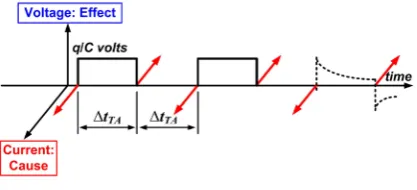
= × . Taking a discharged C shunted by a high resistance to have negligible dissipation during each ∆tTA, let us imagine a series of alternating TA’s taking place in this resistor. The first TA with sign “up” (TA↑) would set a voltage of +q C volts in C and the next TA with sign “down” (TA↓) would reset it to zero volts. A third TA↑ would set +q C volts again and so on. This would create in C
a square voltage wave oscillating between zero and +q C volts with a η=50% duty cycle as shown in
Figure4. If a resistance R2TD sensed this voltage, the active power it would convert into heat on average (e.g. the mean power PR dissipated by R2TD) would be
(
)
2
Figure 4. Hipothetical generation of a square wave of Johnson noise at the maximum rate in a single-electron re-sistor.
leaving as heat this hypothetical device should not surpass the maximum reactive power PQ entering its C by Q
λ TAs per second.
Equating PQ to the power PR dissipated by R2TD in these conditions and using Equation (8) for ∆tTA we have:
2 2 2 2
2TD 2
2TD
1 1
2 2 2 2
Q Q R
q q q q
P P R
C C C C R q
λ
= × = × = = × × ⇒ =
(9)
If a R2TD≈4.1 kΩ really shunted C, the voltage wave would look like that depicted by dashed lines in
Figure4 and Equation (9) would become more complicated. Thus, R2TD would be a resistance that multiplied by
C gives an estimation of the minimum time interval between TA’s for an electron able to give a TA in the device. This λQ is an upper limit for conducting electrons that could be observed in nanodevices with few electrons
involved in conduction processes but the huge number of carriers in macroscopic resistors would make valid the limit fQ. Note that the waveform ofFigure4 only seeks to show the electrical meaning of R2TD. This periodic voltage wave only is an unlike situation because due to the randomness of the TAs, there would be an added “jitter” in each ∆tTA given by Equation (8). We refer to the fact Equation (1) for the energy ∆U considered a discharged C, but this null voltage only is the mean and most likely value. The actual situation, however, would be the one we have left aside where some positive or negative charge could exist in C due to preceding TAs. In this case ∆U would vary randomly with time and so would do the series of ∆tTA. This would add a jitter in time to the waveform ofFigure4.
It is worth noting that with these limits ( 1
TA
1 s
Q t
λ = ∆ −
or the fQ limit) the random series in time of
inter-actions giving rise to electrical noise is tractable as a random series of collisions suffered by corpuscular elec-trons randomly wandering in the atomic lattice of Solid-State devices with a mean collision time δtc = ∆tTA or
( )
1 2
c Q
t f
δ = respectively. This model leads to a Lorentzian spectrum for the Johnson noise of macroscopic resistors whose cut-off frequency fC uses to fall in the tens of GHz for δtc in the picosecond range. Taking a
mean collision time δtc =8 ps for these electrons colliding within the atomic lattice of a resistor of R = 1 kΩ we have fC =20 GHz, thus fC fQ ≈6 THz at room T. This leads to think that the random wandering of
these electrons within the volume VQ of the resistor really takes place and prevents the observation of the
Ny-quist limit fQ at room T for example. To say it bluntly: the flat noise density 4kTR V
2
/Hz decaying as 2 1 f
from f ≈ fC =20 GHz hardly would be useful (measurable) at frequencies f ≈ fQ ≈6000 GHz to show the
Nyquist limit. Added to this, a lower cut-off frequency fRC could appear due to the bandwidth limit set by Cstr, the stray capacitance added by the wires connecting the resistor to the front-end stage of the noise voltmeter or spectrum analyser.
Taking Cstr ≈0.1 pF, the time constant τRC =RCstr =100 ps that results for R = 1 kΩ means that the flat Johnson noise 4kTR V2/Hz decaying as 2
1 f from frequencies f ≈ fRC =1.6 GHz hardly would be measur-able at f ≈ fQ and even at f ≈ fC =20 GHz. However, this fRC limit due to the electronics recalls that the
inner material of the resistor behaves as an RC circuit due to its non-null dielectric relaxation time τmat. Al-though this effect of τmat could be taken into account easily by adding a small capacitance to Cstr [4], the physical meaning of τmat raises a problem. For τmat =1 ps that would be typical for n-type silicon this means that a charge unbalance within the volume VQ of the resistor would disappear from its volume towards its
sur-face with lifetime τmat =1 ps. Thus, it is hard to imagine a negative point charge like a corpuscular electron wandering within VQ with mean collision time δtc =8 ps, whereas its lifetime only is τmat =1 ps within
Q
where its negative charge cloud would screen an equal but positive charge +q also distributed in VQ. Otherwise
the electron cloud would leave the inner volume going towards the surface. The spatial distribution of this cloud would be described by the Ψ3D wave function. With this model and the Ψ → Ψ3D 2D collapse we propose for
each TA, the absence of shot noise assigned to conduction currents in resistors was explained and a new view-point on the Joule effect in Solid-State resistors was found [11].
4. The Arrow of Time and Electrical Noise
Observed on the screen of an oscilloscope Johnson noise looks continuous as time passes and independent of the sense time flows. We would say that this random waveform would not show an arrow of time, thus being similar to the undamped oscillation of [13] concerning this point. Nevertheless, the Cause → Effect dynamics of this
noise at microscopic level indicates that the law of causality plays a key role. The deceptive absence of an arrow of time in the macroscopic waveform would show limitations of our noise meter lacking the speed (bandwidth) and amplitude resolution required to resolve the huge rate of voltage pulses like those voltage decays ofFigure 2 that would form this noise. Thus we have a discrete model for electrical noise where the arrow of time that ex-ists at the microscopic level in each DR seems absent in the macroscopic Johnson noise measured between ter-minals.
Arrived at this point, let us consider these sentences about vacuum in [13]: “In fact, the ‘vacuum’ is generally recognized as a kind of quantum field, or quantum ‘media’ in modern physics. From experiments, the ‘vacuum fluctuations’ has been discovered. Therefore, similar to the previous case with macroscopic dissipative force in the above section,‘the arrow of time’ should also exist in the microscopic world”. Agreeing with these sen-tences we would add a quotation to the last one by considering an experiment based on the “empty resistor” of
Figure1 (two parallel, metallic plates in vacuum) that could be considered a parallel-plate capacitor as we used to do before writing [5]. This empty resistor allows avoiding subtleties linked with conduction currents in solid matter, which is replaced by vacuum at temperature T revealed by its background radiation for example. Now let us consider this empty resistor embedded in this vacuum and in TE with it at temperature T. This 2TD where the capacitance C of its parallel-plate capacitor structure would be shunted by its dynamical resistance R at this T [5], is thus a 2TD that would show flat Johnson noise 4kTR V2/Hz up to its cut-off frequency given by
(
)
1 2π
C
f = RC [2].
This 2TD also would be a capacitor at temperature T that would show a mean square noise voltage of kT C
V2. No matter we consider Johnson or kT C noise because they are equivalent, this voltage noise would be sustained in time by a series of TA’s taking place between its terminals (plates of C). Thus, C would be an an-tenna collecting TAs of energy ∆U . This leads to a parallel-plate capacitor of capacitance C coupled with its surrounding vacuum through a random set of discrete TAs that we could assign to some resistance R in parallel with C by Equation (2). This R would be the dynamical resistance R we met in [5] trying to find an inexistent lossless capacitor at T>0 and it would lead to dissipation of electrical energy reflected by an active power
R
P dissipating the active power PC entering this device through the TAs collected by its C. Note that for
0
T> , a weak electron cloud would surround each plate due to thermionic emission, thus giving rise to this R
[5]. This way, the equality PC =PR would hold for this 2TD in TE with its surrounding vacuum at T>0.
Let us note here that TAs are fluctuations of energy in electromagnetic form, thus a form “not tied” to the time flow required to observe dissipation of electrical energy: recall the way a pure fluctuation of electrical en-ergy was obtained in Equation (4) by freezing the time flow around an instant. From this idea we could say that TAs causing noise are not in the “world” (axis) where their effects requiring a time flow to be observed and measured are (seeFigure2). One would say that the random train of δ-like current pulses called TAs is a charge noise insensitive to the passage of time in one sense or another (e.g. its random power along the arrow of time is equal to the random power we would find going backwards in time). Thus we could say that this electromag-netic cause of electrical noise would be quite insensitive to the arrow of time.
en-ergy stored in C is converted by R into heat that leaves the resistor towards its surrounding universe. Note that as soon as electromagnetic energy from “the vacuum between plates” suffers this time-related process in our device at hand (the empty resistor ofFigure1), dissipation is born because the energy thus accumulated in C tries to diffuse outwards and starts to decrease with time. This shows an arrow of time in each microscopic DR although the macroscopic noise would not reveal it. Only at very low T and with very high R values (e.g. at λ rates of a few ATs per second) this Johnson or kT C noise would look like that ofFigure2 (e.g. discrete).
“Dissipation is born” also means that we start to have conduction currents in-phase with any sinusoidal volt-age synthesizing Johnson noise in the resistor. This is Ohm’s Law leading to a striking “arrow of energy conver-sion” in sinusoidal regime. We mean that the product of a sinusoidal voltage by a sinusoidal current due to the existence of such voltage (thus proportional to it or in-phase with it) always leads to dissipation of electrical en-ergy as time passes no matter the sense of this passage. This is so because the mean value of such product (mean active power) always is a non-negative value. This electrical energy per unit time must leave the 2TD where these magnitudes are found in phase because for voltage and current in-phase, this energy loses its electrical form and it no longer can remain in the electrical admittance of the 2TD. This means leakage of electrical en-ergy in the circuit as time passes, hence the name “dissipation” for this leakage, usually in the form of heat.
Quite the contrary, the product of a sinusoidal voltage by a sinusoidal current that is in-quadrature with it, only gives a sinusoidal fluctuation of electrical energy in the 2TD where these sinusoidal magnitudes are found. This is a lossless fluctuation at twice the frequency of the voltage or current terms. In this case the electrical en-ergy keeps its electrical form as it fluctuates with time. This in-quadrature condition appears when the current is proportional to the change with time of the voltage (e.g. to ∂ ∂v t) not to its existence. To keep electrical energy without losses in a 2TD requires keeping sinusoidal voltage and current oscillating in-quadrature. When this ex-act 90˚ phase difference between voltage and current is lost, dissipation or some in-phase current appears to-gether with the arrow of time linked with the damping oscillations considered in [13].
Thus the quotation we would add to this sentence: “the arrow of time” should also exist in the microscopic world” [13] would be to say that in electrical noise the arrow of time appears at microscopic level once each fluctuation of electromagnetic energy in vacuum suffers a time-related process by which it becomes located in some volume of the space by a quantizing element like C. This is a process that changes the electromagnetic form of the energy into a located form like electrical energy in C and once the energy has been located in space, we would start to observe its dissipation, its related arrow of time and even its gravitational field considering its mass. Let us end this Section by recalling that measuring needs a time flow because in a null elapsed time no energy/mass can be exchanged with the 2TD under test. Thus, no information can be obtained nor measured without a time flow. Note that TAs are not an exception to this impossibility of instantaneous displacements of energy/mass in space because the electrical energy ∆U suddenly appearing in C after a TA already was there, but in electromagnetic form. The time interval ∆tTA to prepare a TA, see Equation (8), likely is the time the fluctuation ∆U needs to appear or to be built in this electromagnetic form measured as an instantaneous dis-placement of charge in space. Finally we will say that this instantaneous passage of the electron as a whole in each TA that we have handled for electrical noise led us to leave aside existing models that consider electrical current as a continuous fluid where a fraction of electron can pass between terminals of a 2TD in a given time interval. This approach that is prone to appear when one oversees the capacitance C of a 2TD should be consid-ered with care, however. These cautious words: “conductor of pure resistance R” written by H. Nyquist in [9], likely reflect that the device “resistor of pure resistance R” does not exist in our physical world as we have con-sidered and wrote in [5].
5. Conclusions
Our firm belief that electrical noise in resistors should reveal the discrete nature of electrical signals led us to propose a new model on its origin. This model that is discrete in time treats electrons as electromagnetic waves (displacement currents) across two-terminal devices like resistors. In some circumstances, this model could ex-cel or complement other models based on point charges wandering and colliding within the solid matter.
electrical form located in the resistor by its complex admittance. Once the energy is located in this way, the consequences associated to energy/mass located in a volume of space would start to be observed.
One of these consequences is the appearance of dissipation of the electrical energy stored in C by its inner electric field and the appearance of the arrow of time related with this process. Since our noise model shows dis-sipation for each microscopic event building Johnson noise in resistors but this macroscopic noise would not show such a clear arrow of time when viewed by an oscilloscope, this new noise model we have used could help to better understand the arrow of time at microscopic level in other noisy processes.
Acknowledgements
This work was partially supported by the European Comission through the 7th Framework Program, by the RAPTADIAG project HEALTH-304814 and by the Ministerio de Economía y Competitividad del Gobierno de España through the MAT2010-18933 project.
References
[1] Izpura, J.I. (2011) Journal of Modern Physics, 2, 457-462. http://dx.doi.org/10.4236/jmp.2011.26055 [2] Izpura, J.I. and Malo, J. (2011) Circuits and Systems, 2, 112-120. http://dx.doi.org/10.4236/cs.2011.23017 [3] Callen, H.B. and Welton, T.A. (1951) Physical Review, 83, 34-40. http://dx.doi.org/10.1103/PhysRev.83.34 [4] Izpura, J.I. (2008)IEEE Transactions on Instrumentation and Measurement, 57, 509-517.
http://dx.doi.org/10.1109/TIM.2007.911642
[5] Izpura, J.I. (2009) IEEE Transactions on Instrumentation and Measurement, 58, 3592-3601. http://dx.doi.org/10.1109/TIM.2009.2018692
[6] Izpura, J.I. and Malo, J. (2012) Circuits and Systems, 3, 48-60. http://dx.doi.org/10.4236/cs.2012.31008 [7] Malo, J. and Izpura, J.I. (2012) Circuits and Systems, 3, 61-71. http://dx.doi.org/10.4236/cs.2012.31009 [8] Johnson, J.B. (1928) Physical Review, 32, 97-109. http://dx.doi.org/10.1103/PhysRev.32.97
[9] Nyquist, H. (1928) Physical Review, 32, 110-113. http://dx.doi.org/10.1103/PhysRev.32.110 [10] Grassia, P. (2001) American Journal of Physics, 69, 113-119. http://dx.doi.org/10.1119/1.1289211 [11] Izpura, J.I. (2012) Journal of Modern Physics, 3, 762-773. http://dx.doi.org/10.4236/jmp.2012.38100 [12] Stock, M. (2013) Metrologia, 50, R1-R16. http://dx.doi.org/10.1088/0026-1394/50/1/R1
![Figure 1. Parallel-plate structure found in two-terminal de-vices like resistors and their complex admittance [2]](https://thumb-us.123doks.com/thumbv2/123dok_us/8169530.808343/2.595.204.423.590.695/figure-parallel-plate-structure-terminal-resistors-complex-admittance.webp)