An Access Control Architecture for Microcellular Wireless IPv6 Networks
S. Schmid, J. Finney, M. Wu, A. Friday, A.C. Scott, and W.D. Shepherd
Distributed Multimedia Research Group
Computing Department
Lancaster University, UK
{sschmid, joe, maomao, adrian, acs, doug}@comp.lancs.ac.uk
Abstract
This document introduces a novel access control architecture for publicly accessible wireless overlay net-works. The architecture is designed to address the prob-lems of ubiquitous Internet service provisioning within the city of Lancaster.
The proposed access control mechanism is based on the concepts of secure user authentication, packet mark-ing, and network-level packet filtering. The novelty of the architecture lies in its use of micro-cellular layer three networks to acquire fine grained access control in a link independent manner.
The paper describes the concepts behind the access control architecture and demonstrates to what extent it addresses the security, performance and extensibility concerns of public access packet switched wireless networks.
1.
Introduction
This document proposes a novel access control archi-tecture for a wireless network currently being deployed around the city centre of Lancaster.
A foundation for the network infrastructure has been laid during the GUIDE project [1,2,3], a four year research effort that developed a tourist guide system allowing visitors to explore the historic city led by an electronic guide. The wireless GUIDE terminal informs the user about the city and its attractions, creates person-alised tours based on the user’s interests, helps users to re-orientation themselves when they are lost, and further provides access to a range of simple interactive services (such as messaging, ticket booking, reservation services, etc.).
More recently in the second phase of the GUIDE project [4], the system is evolved farther to promote a sense of community among users of the system (for example, users are made aware of the actions, views and recommendations of other users).
The challenge of the GUIDE II project is to “open up” the network and provide general-purpose, ubiquitous services and applications (including public Internet access) to citizens. As a side-effect of providing connec-tivity to the general public, we hope to encourage the active involvement of a wider community of users in our mobile systems research.
Since the deployment of wireless network technologies in public places bears the danger of unauthorized people gaining physical access to the network, it is important to be able to restrict access to the network only to authorized systems (and users). Therefore, secure user authentication and authorisation, and a reliable access control mecha-nism is vital – particularly for wireless LANs, where the absence of comprehensive security provision has been a hindrance to its widespread adoption.
The deployment of the network infrastructure for GUIDE II and the development of innovative mobile services for the general public will directly interact with the recently formed Mobile IPv6 Testbed collaboration between Cisco Systems, Microsoft Research, Orange and Lancaster University [5].
The remainder of this document is structured as follows: In the next section we discuss the requirements of our access control architecture. Section 3 describes the basic network infrastructure and the access control mechanism proposed by our architecture. Section 4 discusses the implementation status and outlines the main architectural choices. In section 5 we introduce relevant related work, before we finally conclude the paper in section 6.
2.
Requirements
The requirements for our access control architecture are primarily imposed by the research objectives of GUIDE II and the Mobile IPv6 Testbed, and the setting of the network infrastructure around Lancaster.
Mobility – Without doubt mobility is the focal aspect of our research within the Mobile IPv6 Testbed and GUIDE II. It is therefore crucial to design the access control architecture for a highly mobile network envi-ronment, where users frequently roam between wire-less cells and networks.
Security – As the wireless network infrastructure is publicly available throughout large parts of the city centre, a secure access control mechanism is required to restrict services to authorised users only. In addi-tion, the access control architecture must protect the network against internal and external security threats (for example, denial-of-service attacks).
Flexibility – One of the key requirements is flexibility. As we cannot foresee yet what services will be developed within the course of the Mobile IPv6 Testbed research, we require a maximum on flexibility for the access control approach (for example, to support different granularities of control and a broad spec-trum of access policies).
Extensibility – The access control architecture must be extensible to enable the integration of additional functionality or interaction with value-added services (such as accounting, QoS, etc.) in the future.
Transparency – The access control approach must be fully transparent to correspondent nodes (i.e., hosts to which a mobile node is conversing) external to our mobile network in order to ensure full interoperability with the standard Internet.
Usability – User access to the public network infrastruc-ture should be as easy as possible (i.e., simple instal-lation of software at the beginning and continued ease of use).
Scalability – The size of a public network spanning the city centre of Lancaster demands a scalable access control architecture in terms of number of users and end-terminals.
Manageability – In order to facilitate the manageability of user accounts and access policies, a comprehensive management system is required. The access control architecture should also be fairly universal (i.e., inde-pendent from the underlying technologies) to provide a uniform solution across the whole network (avoid-ing the need for administration of multiple systems).
3.
Access Control Architecture
3.1.
Network Infrastructure
The Mobile IPv6 Testbed is constructed along the wireless overlay network concept [6,7], whereby a number of different wireless technologies (such as HSCSD, GPRS and Bluetooth) are used in combination with the GUIDE infrastructure (based on IEEE 802.11 wireless LANs), in order to provide the coverage and network performance required for future network services. This approach was chosen for two reasons. Firstly, it ensures that mobile users maintain access to network resources wherever and whenever possible, as the most appropriate interconnect can be chosen at any given time. Secondly, it is likely to better emulate the network topology of future public access wireless networks – thus providing us with a more realistic test environment.
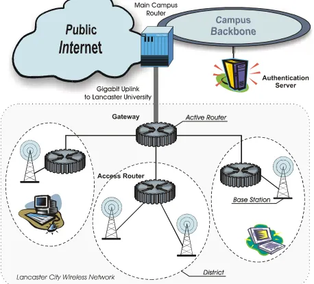
[image:2.595.309.538.442.649.2]Although many of the wireless technologies that will likely make up future overlay networks already have some form of access control (for example, WEP in 802.11 [8] or RLC/MAC in GPRS [9]), those access control mecha-nisms are often quite distinct from each other. As the Testbed is formed from a range of such layer 2 network technologies, the access control mechanism must therefore be independent of those underlying network types. The Testbed addresses this problem by adopting a layer 3 approach to access control.
Figure 1. Access control infrastructure proposed for
the wireless network deployed around Lancaster city.
over-lapping wireless cells, consisting of a variety of technol-ogy ‘flavours’. Adjacent cells of the same flavour can be merged together using layer two bridging in order to form a cell with a larger footprint. Although bridging is an effective means to interconnect a small number of homogenous cells, it is well understood that such archi-tectures do not scale. In addition, when the case of a mobile device crossing between different flavours of net-work is considered, it becomes apparent that bridging provides little support. In order to address these issues, the Testbed network places layer 3 administrative boundaries between cells of different flavours, and optionally between cells of the same flavour. These boundaries sepa-rate logical areas of administrative control, called
districts.
Each district within the Testbed consists of one IPv6 (sub-)network. IPv6 was chosen as the preferred layer 3 protocol for a number of reasons. Firstly, it is widely accepted that IPv6 is likely to play a key role in future generation wireless networks, at the LAN, MAN and WAN level. Choosing IPv6 will provide us with an insight into the problems which may be encountered when deploying such a network, again, giving us a more real-istic testbed. Secondly, IPv6 provides a number of features which make the deployment and management of such a network far simpler. Namely, these are the increased address space offered by IPv6 (allowing for a more scalable solution both in terms of number of users and network cells), the support for host auto-configura-tion, IPsec and mobility. These points are further elabo-rated throughout this document.
As can be seen from Figure 1, each district within the Testbed is served by an access router. This access router is directly responsible for the management of that district, such as IPv6 routing, access control and billing. Access routers are interconnected and linked back to the campus backbone via a wired infrastructure, using SDH, DSL or over point-to-point microwave links.
As one of the aims of the Testbed is to evaluate what role such access points will have in future networks and what services they will provide, it is extremely important to make access routers as flexible and extensible as pos-sible. For this reason, we develop our access point using a high performance component based active network plat-form, namely LARA++ [10]. The access control and router management functions are implemented as LARA++ active services.
3.1.1. Scalability. The use of individually managed IPv6 based cells gives many scalability advantages. Primarily, as there is a vast expanse of available IPv6 address space, it is perfectly feasible to uniquely address each cell within the Testbed as a separate IPv6 network, and still maintain enough space for millions of users per cell. This level of
scalability would be difficult to achieve with IPv4, even through the use of network address translators. Addition-ally, the auto-configuration support offered by IPv6 negates the need for services with higher administration costs, such as DHCP.
The architecture also provides scalability for larger networks. As the access control is enforced by the access router (at the first hop of the wireless network), this distributes the load of access control throughout the network.
Finally, the fact that the wireless cells are routed rather than bridged results in less broadcast traffic on those cells (thus improving network utilisation). In turn, this also improves the security of the network, as it makes it far more difficult for users to snoop packets or masquerade as other network nodes (in the case of a fully routed network, both the attacker and target must be co-located within the same cell, making the attacker much easier to discover and track).
3.1.2. Host Mobility. Although there are clearly many advantages to be gained from having a fully routed network, it does add more complexity to the mobility management subsystem of the network. Consider the case of a mobile device roaming between various flavours of network within the Testbed. As the mobile node crosses an administrative boundary between districts, it sees a change in its IPv6 point of attachment. We envision that these administrative boundaries will be highly common-place, separating areas with differing access control settings. They could be as often as different offices/ laboratories within a building, and different shops within a city. It is therefore vital that the transition between districts is handled smoothly and quickly by the infra-structure. We use Mobile IPv6 to enable this roaming between cells, which provides us with the necessary loca-tion independence and transparency, a distributed mobility management architecture and good handoff performance [11]. However, this adds an additional requirement onto the access control architecture – any authentication or access control mechanisms must not interfere with the performance of the handoff between districts.
3.2.
Access Control Mechanism
The key components of our access control architecture are described here. Figure 1 illustrates how they are situated within our network infrastructure.
• The Authentication Server (AS) is responsible for the authentication and authorisation of clients on the access network. Upon successful authentication and authorisation of a user, the AS issues a limited lifetime access token to the user.
• User end-terminals (i.e., handheld devices, laptops, etc.) request the authorisation of the node on behalf of the current user and perform the packet marking for outbound traffic. A valid access token is obtained from the AS upon successful authorisation of the user. The access token, in turn, provides the basis for the packet marking.
• Access Routers (ARs) control the access to the
protected network. They block traffic originating from or sent to unauthorised end-terminals based on network-level packet filtering. Co-locating the ARs directly with the base stations enables highly flexible access control close to the user (thus mini-mizing the area which can be targeted by an unau-thorized attacker).
• The Gateway connects the access network with the public Internet or a private Intranet (i.e., Campus network). It is concerned with external security threats from arbitrary nodes on the public network and is an extension of the firewall concept.
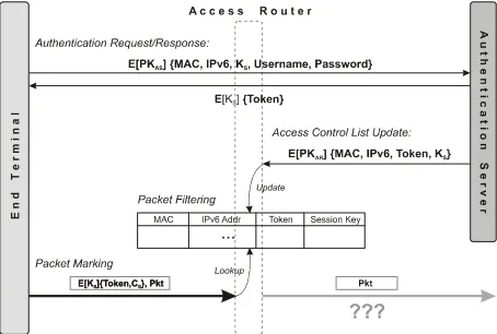
[image:4.595.310.537.495.648.2]The remainder of this section explains step-by-step, how our access control mechanism operates (see also Figure 2 for an illustration of the procedure).
3.2.1. Account Creation. In order to access a publicly accessible network guided with our access control system, a user’s end-terminal requires our Mobile IPv6 stack extension. The user downloads and installs the extension at account setup time.1 The user’s secret credentials (i.e., username and password) are created and registered with the authentication server. The user is also assigned a group, which defines the level of service granted to the user. For example, groups have individual access profiles in terms of which cells they can access (i.e., at what times, and how long or frequently).
In future, we plan to support service differentiation in terms of QoS (i.e., different priority levels, data rate limi-tations, payload volume restrictions) based on the group affiliation.
1 It should be noted here that our extension does not impact the
“normal” use of the Mobile IPv6 stack in conventional networks.
3.2.2. Session Initialisation. Before a user can access the network, the end-terminal requires a valid access token in order to tag packets for transit via the access routers. As a result, the user will be prompted to enter his username and password during session initialisation (for example, when the device is turned on in a cell or at initial network entrance). This process occurs only once per login session as the credentials are cached for the duration of a session.
3.2.3. User Authentication. User authentication is carried out between the user’s end terminal (e.g. PDA or laptop) and the authentication server. The client software takes care of authentication of the user currently logged in.
The authentication request sent from an end terminal to the authentication server includes the user’s username and
password, the node’s MAC Address and IPv6 Address,
and a secret session key. While the username and pass-word are required to authenticate the user, the MAC and IP addresses are needed to authorise the client node on the access routers. As further discussed below, the session key is needed for the encryption of the access tokens, to avoid address spoofing attacks with the network.
In order to prohibit malicious users from spoofing the secret credentials of other users or a session key, the authentication request message must be encrypted. We use public key encryption based on the RSA [12] algorithm and the standard IPsec encryption header [13] in order to avoid the need for a secure key exchange mechanism and a special protocol extension. Public key encryption is advantageous as the client must know only the public key of the authentication server (which can be statically configured) and not vice versa.
Figure 2. Illustration of access control protocol in
3.2.4. Token Generation. Access tokens are the secret credentials that grant packets from authorised end termi-nals access to the protected network. The tokens are issued to particular users upon successful authentication and authorisation.
However, passing the access tokens in clear text to the client would allow malicious users in the same cell to snoop valid tokens. As a consequence, to fully secure the access control mechanism even against MAC address spoofing, the access token requires encryption. The shared session key passed within the authentication request is used for the encryption of the authentication response message.
In order to avoid brute force attacks on access tokens, we chose to restrict the lifetime of the access tokens to a configurable time interval, referred to as the expiration
time of a token. Beyond this interval the extended
proto-col stack must refresh the node’s authorisation based on the cached user credentials to request a new token.
Since the access token is simply a pseudo-random value that is large enough to make it hard to guess or discover by a brute force search within the lifetime of the token, the expiration time must reflect the size of the access token.2 The refresh time of the authentication protocol must be sufficiently smaller than the expiration time.3
The main advantage of those short-lived access tokens is that they provide extra security and robustness. The fact that they change so frequently make them hard to crack.
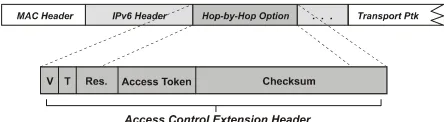
3.2.5. Packet Marking. End terminals use packet mark-ing as a technique to indicate authorised packets to the access routers. When the Mobile IPv6 stack forwards a packet, it includes our access control extension within the Hop-by-Hop Option extension header of the IPv6 packet as illustrated in Figure 3. This header contains the access token and a checksum besides usual housekeeping infor-mation (i.e., protocol version and encryption type). The token and checksum are both encrypted using the session key associated with the access token. The checksum is required as a measure against replay attacks. It prevents a potential attacker from simply snooping the extension header and adding it to their own data.
Since the extension header must be attached to all data packets, a very lightweight encryption mechanism is required. We therefore use a symmetric cipher in order to avoid the performance overhead of asymmetric crypto-graphic algorithms.
2 Since we encrypt the 32-bit access token together with a 96-bit
checksum, we currently use a 10 minute expiration time.
3
We suggest a refresh time that equals to: Trefres = min{Texpiration – 2 ¯
[image:5.595.312.535.109.170.2]avg( Tauthentication ), ¯ Texpiration}
Figure 3. The Access Control Extension Header is added to the IPv6 packets as part of the Hop-by-Hop Option header – A 4-bit version and type field is used to indicate the protocol version and encryption type, and a 128-bit field to hold the access credential: EKs{access token, checksum}.
3.2.6. Packet Filtering. The access control mechanism described so far is based on network-level packet filtering. Access routers check packets sent to and from the end terminals for authorisation. While packets sent to the wireless network must have the destination address of an authorised end terminal, packets sent from a client node must carry a valid access token.
For this, each access router maintains an access control list (ACL) that accommodates all the filter information required to identify ‘authorised’ packets, namely the MAC address, IPv6 address, access token, and session key for each authorised end terminal. The access routers receive this information from the authentication server when a user of the cell successfully authenticates with the network.
When a packet is received from the wireless network, the access router looks up the MAC address in the ACL. If an entry for the end-terminal exists, the access router verifies the IPv6 source address. In the case of a match, it decrypts the access token and checksum using the session key (held within the ACL) and validates its content against the ACL. When successful, the Hop-by-Hop Option containing the access control extension header is stripped off and the packet is passed on. Packets that fail any of those tests (for example, due to an unknown MAC address, a wrong IPv6 address match, or an invalid or expired token) are dropped. One exception to this rule is that when a client is first seen in a cell, it is allowed to contact certain well-known IPv6 addresses; this allows nodes to initially communicate with the authentication server.
The soft-state authentication protocol facilitates fine-grained access control with respect to time and location. It allows end-terminals to be restricted to certain districts based on time. Furthermore, the soft-state approach eases the withdrawal of access privileges. For example, a user who is caught using the network in an inappropriate way or who runs out of online time credit can be denied access to the network by simply refusing further access tokens refreshes.
3.2.7. Roaming Support. In networks such as ours, support for roaming users that frequently move between microcellular networks is crucial. From a network-level point of view, roaming support (i.e., location transparency and fast network handoffs) is provided through the Mobile IPv6 protocol. With respect to our access control archi-tecture, we therefore focus on minimising the impact of access control on handoff performance.
When a mobile node moves into a new network cell, it acquires a new care-of-address (CoA) to reflect its new physical network location4. As a result of the network handoff, the network access will also be controlled by a different access router, which may have no knowledge of previous authorisations for the mobile node. Unfortu-nately, our current solution could take up to several minutes (i.e., until the next authentication refresh is carried out) before the mobile node would obtain access to the network again.
Since service disruptions of this order are clearly not acceptable for networks such as the Mobile IPv6 testbed, we introduced three special measures:
1. Mobile nodes immediately initiate a fresh authenti-cation cycle for the node’s new IPv6 address immediately after a network handoff.
2. The authentication server sends the periodic ACL updates not only to the client’s access router, but also to the neighbouring access routers in order to ‘preheat’ their access control lists with authorisa-tions for potential roaming clients. Note that with the emergence of the context transfer protocol [14] currently being discussed within the IETF, we consider using this ‘proactive’ means to transfer ACL state from previous to new access routers. 3. Access routers grant a short reprieve time for
roam-ing nodes enterroam-ing a cell, before they block traffic from the node. This technique preserves safety by granting access to packets based on a node’s previous authorisation. Due to the preheating of the neighbouring access routers, a node’s new access
4 This can be achieved either through DHCP (v4/v6) or the
auto-configuration mechanisms of IPv6.
router will already have an entry in its access control list when the node moves into its coverage area. This allows packets with a valid MAC address and access token to pass for the period of the reprieve time. However, if the router does not receive a fresh access list update for the node’s new IPv6 address before the reprieve time expires, traf-fic will be blocked.
These extensions have the advantage that they do not interfere with or slow down network-level handoffs. The initial user authentication required when entering a new district is simply delayed (i.e. carried out in the back-ground) to avoid extra latency.
The reprieve time must be chosen carefully. On the one hand, the interval should be minimal as it gives provi-sional access to users based on their previous authorisa-tion while, on the other hand, it must be long enough to complete a whole authorisation cycle.5
3.2.8. Core Network Protection. The design of our access control architecture assumes that the core network can be trusted. This assumption seems reasonable, since the access routers and the authentication server typically belong to the same administrative domain. In our network, for example, the access routers are physically protected by locked cabinets in buildings not open to the general public, and the physical links from the access routers back to the campus network are hard to intercept. However, in case we identify fraudulent misuse within the core network or in network segments that are not trusted, we fall back to use end-to-end encryption for communication between the authentication server and the access routers. For this, standard public key encryption as supported by IPsec [13] is recommended.
In addition, we plan to use the gateway router (Figure 1) as a firewall for the core network. For security reasons and to avoid denial-of-service attacks, it will strictly block remote traffic (sourced from the public network) directly sent to the access routers. To minimise the risk of denial-of-service attacks on the clients, the gateway could poten-tially rate-control transmissions to end-terminals.
3.2.9. Enhanced Security. In cases where users demand a high level of security (for example, full privacy), the architecture supports an additional layer of protection based on full encryption of the payload on the wireless link (i.e., between the access router and client device). This offers an alternative to the IEEE 802.11 wired equivalent privacy (WEP) [8] protocol, which has recently been shown to be vulnerable to attack [15]. We plan to
5 We recommend a reprieve time of approximately 2-5 seconds
allow the user to freely choose the level of security depending on the network use and the end-terminal at hand, as full payload encryption can be very heavyweight for low-performance mobile devices.
Finally, it is worth noting that standard IPsec authenti-cation and encryption are entirely complementary to our access control architecture. They can be used in addition to achieve secure end-to-end communication.
4.
Implementation
This section outlines the implementation of the key components of our access control architecture for the wireless network around Lancaster. Due to the lack of space, we provide only a brief description here.
4.1.
Client Software
According to our architecture the client software is responsible for user authentication and packet marking.
User authentication is performed by a system service executed on the end-terminal. In order to gain access to the network, the user must first provide its username and password to the terminal. The credentials are then stored locally such that the actual authentication (and periodic re-authentication) with the authentication server can be performed by the service without user intervention.
The authentication protocol used for client authentica-tion with the AS is based on a lightweight request/ response protocol. UDP is used for transport. Standard IPsec encryption6 is applied for end-to-end encryption of the authentication request.7 The clients use RSA [12] public-key encryption based on the public key of the authentication server (which can be pre-configured at the client to avoid the need for a key distribution service) to encrypt the authentication request.
As described earlier, the authentication request includes a new session key for the authentication server to establish a secure communication channel back to the client. For the encryption of the authentication response, we use symmetric encryption based on the shared session key. This is accomplished via the tiny encryption algo-rithm (TEA) [16].
In response to an authentication request, the server replies either with a new access token for the client or an error message. In the case of success, the client service
6
Since the requirement to support IPsec in Mobile IPv6 has been dropped while we were designing our protocol, we may have to use a proprietary end-to-end encryption solution in the future.
7
For this to work in the absence of a global public key infrastructure, we statically configure the security association (SA) for the authentication server on the client. Based on this SA, IPv6 knows how to encrypt/decrypt data packets send to or received from the authentication server.
decrypts the authentication response using the current session key and passes the token to the protocol stack for the packet marking.
As highlighted earlier, our extended protocol stack also perform the packet marking, including the most recent access token into every packet (see Figure 3) to indicate the client’s access credentials to the access routers. To prevent MAC address spoofing and replay attacks based on a spied access token, we encrypt the token along with a packet checksum (using the shared session key). The 96-bit checksum is computed from frequently changing protocol fields of the IPv6 header (namely the source and destination address, flow id, and, payload length), the transport protocol header (namely the source and destina-tion port, and checksum), and limited data of the payload using MD5 [16]. In order to minimise the latency due to encryption of the access credentials, we use the fast block cipher TEA [17]. The lightweight algorithm has no known cryptanalysis and is claimed to be at least as secure as the well-known IDEA cipher.
We have chosen to use the Mobile IPv6 protocol stack as a starting point to add the extra functionality required for packet marking because of the experience we have gained with this protocol stack in recent years. In particu-lar, we support the protocol stacks for Microsoft Windows 2000 and Linux, since we have implemented both stacks within previous projects at Lancaster [18,19].
4.2.
Authentication Server
The authentication server runs a user-level application or service responsible for managing the user accounts, and the authentication and authorisation of the users and their terminals.
Upon receipt of an authentication request (on the well-known server port), the authentication application tries to authenticate the user. On success, it sends the authentica-tion response message including the access token back to the client and triggers the dissemination of the access control list update to the respective active router(s).
The authentication server uses a standard Mobile IPv6 stack with support for IPsec in order to provide the cryp-tographic means for the encrypted communication channel to the end-terminals (and potentially the access routers). A dynamic mechanism to add and remove IPsec security associations will be provided to allow the authentication service to flexibly define how authentication messages are encrypted (and decrypted respectively).8
8
For the transport of our application-level authentication protocol we use UDP. Since the authentication protocol is fairly lightweight (i.e. only small amounts of data are exchanged), it does not justify the overhead of establish-ing separate TCP sessions for each authentication cycle. Reliability is achieved by means of a simple client driven retransmission strategy.
Although the use of UDP for the transport benefits scalability of the authentication server, the bottleneck in our architecture is still the centralised server. To over-come this limitation, we plan to exploit the new IPv6 feature anycast. This novel addressing scheme enables replication of servers behind a single anycast address to increase availability and redundancy.
4.3.
Access Router and Gateway
The access routers and the gateway firewall are based on the LARA++ active router architecture [10]. LARA++ is a component-based active router platform that supports dynamic extensibility of the router functionality through remote loading and on-the-fly instantiation of active components. A sophisticated composition framework enables flexible integration of these components into the packet processing chain on the router, where they provide additional functionality.
Initially, the packet filtering and access control list management will be implemented as active LARA++ components. The ACL management component listens for ACL updates (i.e., UDP datagrams sent to a well-known port on the router) and updates its access control list accordingly. The packet filter component in comparison intercepts inbound traffic (originating from the end-termi-nals) to verify their access credentials. If valid, the filter component removes the Hop-by-Hop Option including the access control extension header and forwards the packet; otherwise it drops the packets. Outbound traffic, in contrast, is intercepted to check whether or not it is destined to authorised clients.
The gateway router will include a number of active components that attempt to secure the access network from malicious external nodes. These components will try to detect denial-of-service attacks (for example, ping floods) by external nodes based on packet analysis (i.e., packet type, source address, data rate, etc.).
5.
Related Work
The design of our architecture has drawn on the experience of earlier public access control research. In particular, we have combined a range of existing ideas with our own expertise in active and mobile networking and protocol design to develop a flexible, lightweight,
scalable and secure access control solution with special support for mobile environments.
Two early access control systems, namely Carnegie Mellon’s NetBar system [20] and the public access system developed at UC Berkeley [21], use specialised hardware (i.e. hubs, switches) to control network access on a port basis. Both solutions dynamically enable or disable link-layer access to network ports based on user authentication. While CMU’s NetBar system is based on a remote configurable VLAN switch, Berkeley’s solution relies on an intelligent hub. Despite the fact that both solutions require expensive specialized hardware, they are not practical for wireless networks, where many end-terminals share the same base station and hence the same network port on the switch/hub.
A more promising hardware-centric approach was recently announced by the IEEE 802.1X standardisation body. The port-based network access control [22] performs layer 2 authentication of the host to obtain access to a switch LAN by means of the extensible authentication protocol (EAP). This approach provides per-port access control at the first point of attachment (the edge). The fact that our infrastructure is based on micro-cellular layer 3 networks, which can exactly correspond to the link-layer cells, allows our solution to support access control at the same granularity than port-based network access control.
The systems described above are all limited to address a single aspect, namely access control. Our architecture in comparison is provisioned to address supplementary aspects of a public access infrastructure, such as account-ing, quality of service, monitoraccount-ing, or detection of security attacks. Especially the use of dynamically extensible active routers inside the access network provides great flexibility for future integration of additional functionality and services as they are needed or being developed.
However, the major difference to the access control approach introduced so far is probably that our architec-ture performs access control at the network-layer rather than the link-layer. The advantage of layer 3 access control is that it can be used as a uniform mechanism across many link-layer technologies. Current link-layer access control solutions are still predominantly based on the idiosyncrasies of the technology at hand, although standardisation efforts are under way.
meas-ures against MAC address spoofing). The more recent CHOICE system in comparison accomplishes a high-level of security through the concept packet marking and packet filtering. Successfully authenticated and authorised users receive a token at session initialisation time. A custom network device driver on the client attaches the tag to every outbound data packet to indicate its authorisations. The architecture involves separate authoriser and verifier gateways in addition to a central authentication server. While the authoriser gateway enables restricted access to the authenticator only, the verifier gateway grants full access to the network based on the packet tags.
Although based on the same access control principles, our approach distinguishes itself from CHOICE in a number of ways. Three key differences are: First, we introduce the concepts of short-lived access tokens and session keys, and a soft-state authentication protocol to enhance robustness and security. The fact that the user’s security credentials (tokens and keys) are frequently renewed enables the use of lighter weight crypto systems without sacrificing security. Second, our access control architecture accounts for smooth handoffs between layer 3 networks. Our approach is therefore not restricted to link-layer handoffs and a single link-layer 3 network, which makes our architecture more scalable than CHOICE. Third, we introduce the concept of microcellular administrations (referred to as districts) to enable fine-grained access control, accounting and monitoring, which considerably improves flexibility (for example, a wide range of access policies and accounting models can be implemented).
Furthermore, unlike CHOICE and SPINACH, our architecture does not rely on the availability of other high-level services, such as DHCP for auto-configuration of the client terminals and HTTP (and SSL) for Web-based user authentication. Instead, our clients use the standard IPv6 auto-configuration mechanism to obtain a network address, IPsec encryption to secure the authentication protocol, an extension to the Mobile IPv6 stack to accom-plish packet tagging, and a lightweight request/response authentication protocol (based on UDP).
Finally, our system will allow standard IPv6 applica-tions to run over the public access infrastructure. In order to overcome the problem of limited IPv6 support in current applications, we are working simultaneously on an IPv4 in IPv6 encapsulation protocol, which enables the use of unmodified legacy IPv4 applications over an IPv6 island (and hence over our public access network) [25].
6.
Conclusion
This paper introduced an innovative access control architecture, designed for metropolitan area public access wireless networks. The network infrastructure and access
control mechanism described offers a number of impor-tant distinguishing features from other related approaches:
• Support for fine-grained access control: The use of IPv6 to provide microcellular administrative boundaries (districts) enables the enforcement of sophisticated multifaceted access control policies. In addition to temporal information, access control policies can also comprise spatial information (i.e., which cell(s) a user has access to at certain times).
• Scalable access control infrastructure: The parti-tioning of the public network infrastructure into many separate administrative districts and the distribution of access control processing load across multiple access routers constitutes a system scalable to a large number of users, terminals and cells. Also, the integration of the overlay network concept allows for the scalable provision of access networks to users.
• Highly secure access control: The use of soft-state based authorisation (in conjunction with the peri-odic authentication protocol) offers a high level of security, as secret credentials (i.e. access tokens, session keys) are re-issued at a configurable inter-val. This greatly reduces the risk of brute force or spoofing attacks.
• Optimised access control for roaming users: Support for roaming users in mobile environment is inherent to the architecture. A short reprieve time combined with intelligent distribution of ACL state information among access routers enables smooth network handoffs between access districts.
In addition, our access control implementation is novel for a number of technical reasons including the use of Mobile IPv6 to support public access control and the use of active router technology to speed up the development and continued refinement of the system. The tight integra-tion of the access control system with our Mobile IPv6 stacks allows for a system which adapts quickly to changes in network environment (such as handoffs), while maintaining location transparency for applications and a high level of security. The use of LARA++, our compo-nent-based active router, is expected to be an ideal plat-form for the packet filtering component and ultimately for further network management services such as accounting and billing.
Acknowledgements
Cambridge U.K. [19], and the EPSRC funded GUIDE II project (GR/M82394) [4]. The project also has received support from Cisco Systems, HP Labs (Bristol), Lucent Technologies and Orange.
References
[1] N. Davies et. Al, “Caches in the Air: Disseminating Information in the Guide System”, in Proceedings of IEEE Workshop on Mobile Computing Systems and Applications (WMCSA '99), New Orleans, February 1999.
[2] K. Cheverst, N. Davies, K. Mitchell, A. Friday, “The Role of Connectivity in Supporting Context-Sensitive Applications”, in Lecture Notes in Computer Science No. 1707, Springer-Verlag Heidelberg, pp 193-207, 1999.
[3] K. Cheverst et. Al, “Developing a Context-aware Electronic Tourist Guide: Some Issues and Experi-ences”, in Proceedings of CHI ’00, Netherlands, pp 17-24, April 2000.
[4] Guide II: “Services for Citizens”, Research Project, Lancaster University, EPSRC Grant GR/M82394, 2000.
[5] Mobile IPv6 Testbed, Collaboration with Cisco, Microsoft and Orange, Lancaster University, avail-able via the Internet at http://www.mobileipv6. net/testbed, February 2001.
[6] M. Stemm, R.H. Katz, “Vertical Handoffs in Wire-less Overlay Networks”, ACM Mobile Networking (MONET), 1997.
[7] T.S. Rappaport, “Wireless Communications – Principles and Practice”, Prentice Hall Publishing, 1996. ISBN 0-13-375536-3.
[8] LAN MAN Standards Committee of the IEEE Computer Society, “Wireless LAN medium access control (MAC) and physical layer (PHY) specifica-tions”, IEEE Standard 802.11, 1999.
[9] Nokia, “General Packet Radio Service – GPRS – Nokia’s vision for a service platform supporting packet switched applications”, White Paper, 1998. [10] S. Schmid, J. Finney, A.C. Scott, W.D. Shepherd,
“Component-based Active Network Architecture”, in Proceedings of 6th IEEE Symposium on Com-puters and Communications (ISCC ’01), Hamma-met, Tunisia 3-5 July, 2001.
[11] J. Finney, “Supporting Continuous Multimedia Ser-vices in Next Generation Mobile Systems”, Ph.D. Thesis, Lancaster University, September 1999. [12] B. Kaliski, J. Staddon, “PKCS #1: RSA
Cryptog-raphy Specifications”, IETF Internet RFC 2437, October 1998.
[13] S. Kent, R. Atkinson, “Security Architecture for the Internet Protocol”, Internet RFC 2401, November 1998.
[14] O. H. Levkowetz et. Al., “Problem Description:
Reasons For Performing Context Transfers between Nodes in an IP Access Network”, Internet
Draft, draft-ietf-seamoby-context-transfer-problem-stat-02.txt, June 2001.
[15] W. Arbaug, N. Shankar, Y.C.J. Wan, “Your 802.11 Wireless Network has No Clothes”, Technical Report, Department of Computer Science, Univer-sity of Maryland.
[16] R. Rivest, “The MD5 Message-Digest Algorithm”, IETF Internet RFC 1321, April 1992.
[17] D. Wheeler, R. Needham, “TEA: a Tiny Encryption Algorithm”, Technical Report, Computer Labora-tory, Cambridge University, UK.
[18] J. Finney, A.C. Scott, “Implementing Mobile IPv6 for Multimedia”, in Proceedings of 1st GEMISIS symposium on Multimedia Network Technology, Salford, UK, May 1998.
[19] The LandMARC Project, Research Project, Lancas-ter University, available via the InLancas-ternet at http://www. LandMARC.net, October 1999.
[20] E. A. Napjus, “NetBar - Carnegie Mellon’s Solution to Authenticated Access for Mobile Machines”, CMU White Paper, http://www.net.cmu.edu/docs/ arch/netbar.html
[21] D. L. Wasley, “Authenticating Aperiodic Connec-tions to the Campus Network”, June 1996,
http://www.ucop.edu/irc/wp/wpReports/wpr005/ wpr005_Wasley.html
[22] IEEE Draft P802.1X/D1, “Port Based Network Access Control”, September 1999.
[23] E. Poger, M. Baker, “Secure Public Internet Access Handler (SPINACH)”, in Proceedings of the USENIX Symposium on Internet Technologies and Systems, 1997.
[24] A. Miu, P. Bahl, “Dynamic Host Configuration for Managing Mobility between Public and Private Networks”, in Proceedings of the 3rd Usenix Internet Technical Symposium, San Francisco, Cali-fornia, March 2001.