http://dx.doi.org/10.4236/cn.2013.54035
On Ultra Extended Cyclic Prefix in Orthogonal
Frequency Division Multiplexing (OFDM) Systems:
The Case of LTE Downlink
Abayomi M. Ajofoyinbo
Department of Systems Engineering, Faculty of Engineering, University of Lagos, Lagos, Nigeria Email: [email protected], [email protected]
Received July 5, 2013; revised July 30, 2013; accepted August 5, 2013
Copyright © 2013 Abayomi M. Ajofoyinbo. This is an open access article distributed under the Creative Commons Attribution Li- cense, which permits unrestricted use, distribution, and reproduction in any medium, provided the original work is properly cited.
ABSTRACT
Orthogonal Frequency Division Multiplexing (OFDM) is a multi-carrier scheme used in modern broadband wireless communication systems to transmit data over a number of orthogonal subcarriers. When transmitted signals arrive at the receiver by more than one path of different length, the received signals are staggered in time; this is multipath propaga- tion. To mitigate the effect of dispersed channel distortion caused by random channel delay spread, Cyclic Prefix (CP) is introduced to eliminate Inter-Symbol Interference (ISI). In the literature, researchers have focused on carrying out investigations (or studies) mainly on the two existing CP insertions, namely: normal and extended CPs. Both CPs have limitations with respect to handling channel delay spreads. In the current work, a new CP, herein referred to as “ultra extended” CP is proposed to address delay spreads beyond the limits of the normal and extended CPs. The efficacy of the proposed ultra extended CP is tested via simulation under different scenarios. It is shown by the results obtained that the proposed CP can efficiently handle delay spreads beyond the limits of the existing normal and extended CP, and can indeed be implemented in the design of future telecommunication systems to accommodate higher channel delay spreads and it ensures wider cell coverage.
Keywords: OFDM; Normal; Extended; Ultra Extended; Cyclic Prefix; LTE
1. Introduction
Orthogonal Frequency Division Multiplexing (OFDM) is a multi-carrier scheme used in modern broadband wire- less communication systems to transmit data over a num- ber of orthogonal subcarriers. Whereas conventional transmission uses only a single carrier modulated with all the data to be sent, OFDM breaks the data to be sent into small chunks, allocates each sub-data stream to a sub- carrier and subsequently sends the data in parallel or- thogonal sub-carriers. OFDMA (orthogonal frequency division multiple access) dynamically assigns subset of sub-carriers to individual users using either Time Divi- sion Multiple Access (TDMA—i.e., separate time frame) or Frequency Division Multiple Access (FDMA—i.e., separate channels) technique. In the Long-Term Evolu- tion (LTE) systems, two frame types are supported namely: Type 1 (used in Frequency Division Duplex- ing—FDD) and Type 2 (used in Time Division Duplex- ing—TDD). OFDMA at the physical layer, in conjunc-
tion with a Medium Access Control (MAC) layer, pro- vides optimized resource allocation and quality of service support for different users. The smallest modulation structure in LTE is one symbol in time domain and one subcarrier in frequency domain. The size of various fields in the time domain is expressed as a number of time unit
Ts
32.25 nanoseconds. Downlink and uplink trans-missions are organized into radio frames with frame du- ration Tf = 10 ms duration. The time and frequency do-
termed Resource Grid (RG), and the smallest unit, one symbol length on one sub-carrier, is called a Resource Element (RE). In case of multi-antenna transmission, one RG is defined per antenna port. Allocation of RBs to user is done by the scheduler and scheduling decision is taken during each Transmission Time Interval (TTI) of 1 ms for each sub-frame. Ajofoyinbo and Orolu [1] proposed an optimal allocation technique of radio resource in cel- lular LTE downlink based on truncated dynamic pro- gramming under uncertainty. In an earlier work, the au- thors proposed an optimal allocation methodology of radio resource in cellular LTE downlink based on dy- namic programming (Ajofoyinbo and Orolu [2]). A radio frame carries both physical channels and physical signals. When transmitted signals arrive at the receiver by more than one path of different length, the received signals are staggered in time; this is multipath propagation. To miti- gate the effect of dispersed channel distortion, Cyclic Prefix (CP) is introduced to eliminate Inter-Symbol In- terference (ISI). CP involves copying a section of the end of the main body of an OFDM symbol and appending it to the start of the OFDM symbol. This process does not change the frequency content of the signal as the signal includes the same set of frequency domain component. Guard Interval/Time (GT) is the time spacing between symbols being transmitted to prevent Inter-Symbol In- terference (ISI). It is implemented as CP to completely eliminate ISI and to preserve orthogonality among OFDM subcarriers; provided the GT length is suffi- ciently greater than channel delay spread. OFDM modu- lation in a transmitter includes Inverse Fast Fourier Transform (IFFT) operation and CP insertion. In OFDM receiver, the CP is removed before the packet data are sent to the Fast Fourier Transform (FFT) operation for de- modulation. The FFT/IFFT provides a means of quanti- fying the set of the frequency domain components in- cluded within a time domain signal. The FFT algorithm computes efficiently components of waveform while IFFT algorithm translates the output of FFT back to sam- pled data. In recent times, researchers have carried out studies in different areas of OFDM systems, especially in relation to mitigating the effect of multipath propagation. In Osman and Rahman [3], a method was proposed to determine the optimal guard time length for mobile WiMAX system over ITU-R M.1225 multipath fading channel. The results show that the optimum values of the GT are approximately dependent on the maximum delay spread. Delay spread values are found to be directly re- lated to the propagation environment and not on the sys- tem operating frequency (Nee and Prasad [4]). Delay spread is not constant in wireless mobile communication channel and its values can span from very small value (say, tens of nanoseconds) to large values (say, micro- seconds) depending on the terrain and distances. Study
carried out by Rappaport et al. [5] revealed that urban areas have Root Mean Square (RMS) delay spreads on the order of 2 - 3 microseconds, about 5 - 7 microseconds in open and hilly residential areas, and high rise urban areas exhibit larger delay spreads in excess of 20 micro- seconds. In their own contribution, Seidel et al. [6] showed that delay spreads are less than 8 microseconds in open in macro-cellular channels, less than 2 micro- seconds in micro-cellular channels, and 50 - 300 nano- seconds in pico-cellular channels. Moreover, the work of Rappaport [7] revealed that for indoor office building, RMS delay spread is 35 nanoseconds, while at factory buildings the delay spread goes up to 300 nanoseconds. In Tarasak et al. [8], it was shown that with only two transmit antennas, Cyclic Delay Diversity (CDD) effec- tively improves symbol error rates performance and re- duces outage probability significantly especially when channel delay spread is short. Siddiq [9] investigated variable length CP in OFDM using multipath delay tracking and found that the proposed system saves about 47.6% of the time and power spent by the same constant length CP in OFDM system tested under the same condi- tions. Ghanbarisabagh et al. [10] investigated the prob- lem of cyclic prefix reduction for OFDM system over multipath fading channels, and proposed two Time-do- main Equalizer (TEQ) schemes for OFDM systems oper- ating two-path fading channel to cancel the residual ef- fect of ICI and ISI caused by the CP length being shorter than the Channel Impulse Response (CIR). The authors found that the proposed receiver can achieve better Bit Error Rate (BER) performance than the conventional OFDM receiver under two-path fading channel. Li et al.
covers problem solution. Simulation and discussion of results are presented in Section 4 and Section 5 con- cludes the paper.
2. Problem Definition
In the downlink and uplink of UMTS (Universal Mobile Telecommunication System) LTE, transmissions are or- ganized into radio frames that are 10 milliseconds (ms) long in time duration and each radio frame consists of ten sub-frames of 1 ms each. A Resource Block (RB) is one slot in the time domain and twelve consecutive subcar- riers in the frequency domain. RB is the smallest unit to which user traffic is allocated and two users cannot share one RB. Scheduling decision is taken during each Trans- mission Time Interval (TTI) of 1 ms for each sub-frame; which translates to two RBs. Relevant parameters of Type 1 Radio Frame are presented in Figure 1 below.
Time domain fields are typically defined in terms of the basic time unit, Ts(3GPP [12]). That is, the time unit
is given as an integer number of Ts.
FFT 1
s
T
f N
(1)
where NFFT is the FFT size.
1 1 s 32.55 ns
15, 000 2048 30, 720, 000 s
T
One way to prevent ISI is to create a cyclically ex- tended GT where each OFDM symbol is preceded by a periodic extension of the signal itself. The signal is al- ways continuous at the interface between the cyclic pre- fix and the main body of the OFDM symbol. One fun- damental condition for orthogonality between the sub- carriers is that each sub-carrier has integer number of cycles in the FFT processing interval. The resultant effect is that all sub-carriers are mutually orthogonal within the FFT interval.
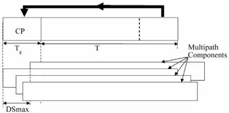
The result of multipath propagation and the mitigating effect of CP are shown in Figure 2. DSmax represents the maximum delay spread.
The duration of the CP should be longer than the dura- tion of the maximum multipath delay spread which can occur in the channel. As presented in Figure 2, the total symbol duration (Ttotal) is given by Equation (2):
total g
[image:3.595.311.538.85.197.2]T T T (2)
Figure 1. Type 1 radio frame.
Figure 2. Result of multipath propagation and mitigating effect of CP.
where Tg is the guard interval/time, and T is the useful
symbol duration.
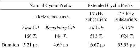
[image:3.595.56.284.337.413.2]LTE specifies both normal and extended CP lengths. The normal CP results in 7 OFDM symbols per slot while the extended CP gives 6 OFDM symbols per slot. Table 1 shows the CP lengths for the downlink of LTE.
In the Base-2 FFT algorithm, 210, 211 and 212 points correspond to 1024, 2048 and 4096 FFT size respectively. The objective of the current work is to investigate the case of an ultra extended CP for 15 kHz subcarriers spacing using 1024 FFT size (i.e., N = 1024 complex samples per OFDM symbol in time domain).
3. Problem Solution
A major parameter associated with the use of OFDM in LTE is the available channel bandwidth as it influences several decisions including the number of sub-carriers in the OFDM signal. The channel bandwidths that are cur- rently supported by LTE are: 1.25 MHz, 2.5 MHz, 5 MHz, 10 MHz, 15 MHz and 20 MHz. The sub-carriers are spaced 15 kHz apart from each other; and to maintain orthogonality among the subcarriers, the symbol duration is defined as the reciprocal of the subcarrier spacing. OFDM symbols have a basic duration of 66.667 µs. This is called the useful symbol duration, which translates to 2048 complex samples per OFDM symbol in the time domain.
3.1. Existing CP Time Durations
As stated in Section 2 above, to provide consistent and exact timing definitions, time intervals within the LTE specifications are defined as multiples of basic unit Ts.
Given that the duration for one slot is 0.5 ms (=500 µs), the existing CP time durations are analyzed as follows:
1) The normal CP
The time duration for the first CP is obtained as:
0
1
CP 160 160 s
30, 720, 000 5.208μs 5.21μs
s
T
[image:3.595.62.288.662.719.2]Table 1. CP lengths for the downlink of LTE.
0 1 4
CP CP CP 1024
1
1024 s 33.3 s
30,720,000
ue ue ue Ts
(7) Normal Cyclic Prefix Extended Cyclic Prefix
15 kHz subcarriers subcarriers 15 kHz subcarriers7.5 kHz
First CP Remaining CPs All CPs All CPs
160 Ts 144 Ts 512 Ts 1024 Ts
[image:4.595.57.287.101.182.2]Duration 5.21 µs 4.69 µs 16.67 µs 33.33 µs
Figure 5 shows the slot structure for the ultra extended CP.
To be sure, one slot (i.e., Tslot) is 0.5 ms duration. From Figure 5,
slot 5 33.3 s 5 66.67 s 500 s 0.5 ms
T
(8)
The value 160 in Equation (3) represents the FFT points. Since number of OFDM symbol per time slot with normal CP is seven, then the CP for the remaining six symbols
CP1,2, ,6 are obtained by Equation (4):Clearly, the reduction in the number of OFDM sym- bols (i.e., from 7 to 6, and now down to 5) as a result of the reduction in the useful symbol time duration, given the increased aggregate CP duration, will lead to de- crease in the number of bits that are transmitted per sub-frame in every TTI. It is assumed in this study how- ever, that the channel performance is not limited (or con- strained) by noise but rather by signal corruption as a result of channel time dispersion caused by longer delay spread. The CPue duration of 33.3 µs is long enough to
cater for multipath propagation (or delay spread) beyond the capability of existing extended CP which currently accommodates delay spread of up to 16.67 µs.
1 2 5
CP CP CP 144
4.6875 s 4.7 s
s
T
(4)
Figure 3 shows the slot structure for the normal CP insertions.
2) The extended CP
The time duration for the first CP is obtained as:
0
1
CP 512 512 s 16.67μs
30,720,000
s
T
(5)
The value 512 in Equation (5) represents the FFT points (i.e., FFT size). Extended CP yields six OFDM
symbols per time slot, and im-
plies that: 0 1
CP CP CP
Table 2 shows the modulation schemes and applicable bits/symbol.
There is a need to test the effectiveness of the pro- posed ultra extended CP in relation to data transmission and channel throughput. The effects of the proposed “ul- tra-extended” CP on data transmission are investigated via simulation in Section 4.0. The simulation is imple- mented in Microsoft Visual C# 2008 and MATLAB ver- sion 7.10.0.499 (R2010a).
5
0 0 5
CP CP ... CP 16.67μs (6)
Figure 4 shows the slot structure for the extended CP insertions.
3.2. The Proposed Ultra Extended CP
4. Simulation and Discussion of Results
OFDM subcarrier spacing of Δf = 15 kHz and 12 con-secutive subcarriers during one slot correspond to one downlink RB. In addition, there is also a lower subcarrier spacing of Δflow = 7.5 kHz, which are exclusively used for MBMS (multimedia broadcast multicast service) with all cells on the same frequency (3GPP [13]). In the case of 7.5 kHz subcarrier spacing, there is only a single CP length, TCPlow = 1024 * Ts, corresponding to three
OFDM symbols per slot. The introduction of the 7.5 kHz sub-carrier spacing is only partly implemented in the LTE specifications. In this paper, we proposed an exten- sion to the existing extended CP, based on subcarrier spacing of Δf = 15 kHz, which is herein referred to as “ultra-extended CP”. The proposed “ultra-extended” CP (i.e., CPue) yields five OFDM symbols per time slot. The
time duration for the CP is obtained by multiplying the basic time unit (Ts) by 1024. The 1024 represents appli-
cable number of FFT points (i.e., FFT size). The time duration of the “ultra-extended” CP is subsequently com- puted as follows:
Recall that the proposed ultra extended CP yields five OFDM symbols per time slot, resulting in ten OFDM symbols per sub-frame. It is assumed that three of the ten OFDM symbols in a sub-frame are used for channel sig- naling. This gives seven symbols per sub-frame for ac- tual data transmission.
4.1. Simulation Parameters
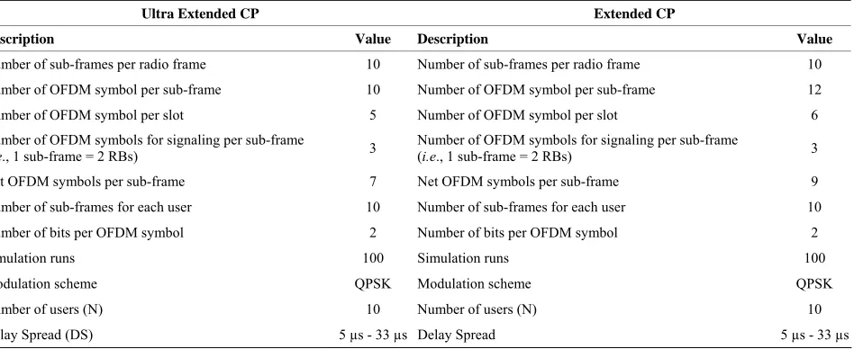
Relevant simulation parameters are presented in Table 3. In this paper, it is assumed that channel performance is not constrained by noise but rather signal corruption as a result of channel time dispersion caused by longer delay spread.
The following variables are defined:
ext —Net OFDM symbols/sub-frame for ex-
tended CP
ofdm
u ext—Net OFDM symbols/sub-frame for ultra
extended CP
Figure 3. 7 OFDM symbols and 7 CP per.
Figure 4. 6 OFDM symbols and 6 CP per slot.
[image:5.595.64.535.85.514.2]Figure 5. 5 OFDM symbols and 5 CP per slot
Table 2. Modulation schemes and bits/symbol.
Modulation Scheme Bits/symbol
[image:5.595.66.540.324.518.2]QPSK 2 16QAM 4 64QAM 6
Table 3. Simulation parameters.
Ultra Extended CP Extended CP
Description Value Description Value
Number of sub-frames per radio frame 10 Number of sub-frames per radio frame 10
Number of OFDM symbol per sub-frame 10 Number of OFDM symbol per sub-frame 12
Number of OFDM symbol per slot 5 Number of OFDM symbol per slot 6
Number of OFDM symbols for signaling per sub-frame
(i.e., 1 sub-frame = 2 RBs) 3
Number of OFDM symbols for signaling per sub-frame
(i.e., 1 sub-frame = 2 RBs) 3
Net OFDM symbols per sub-frame 7 Net OFDM symbols per sub-frame 9
Number of sub-frames for each user 10 Number of sub-frames for each user 10
Number of bits per OFDM symbol 2 Number of bits per OFDM symbol 2
Simulation runs 100 Simulation runs 100
Modulation scheme QPSK Modulation scheme QPSK
Number of users (N) 10 Number of users (N) 10
Delay Spread (DS) 5 µs - 33 µs Delay Spread 5 µs - 33 µs
i
Tb Tb
—Total bits available for transmission for user i
e i —Bits available for transmission for user i using
extended CP
ue i—Bits available for transmission for user i using
ultra extended CP
Tb
e i
Tx
Tx
—Transmitted bits for user i using extended CP
ue i —Transmitted bits for user i using ultra ex-
tended CP
subf —Number of sub-frames used for transmission
by each user
N
CPe-i—Extended cyclic prefix for user i
CPue-i—Ultra extended cyclic prefix for user i
Data transmission for each user is modeled by Equa- tions (9) to (16):
9
ext
ofdm (9)
7
u ext
ofdm (10)
Equations (9) and (10) specify the number of OFDM symbols per sub-frame after making provision for three symbols for signaling. In this paper, every user’s data are transmitted using the two CP types namely: extended CP and ultra extended CP. Equations (11) and (12) show initial total bits for transmission by each user using ex- tended and ultra extended CPs respectively.
e i i
Tb Tb (11)
ue i i
Tb Tb (12)
A user has integer multiples of allocated sub-frames for transmission; noting that a sub-frame consists of two RBs. Hence, Nsubf ranges from 1 to 10, per radio frame.
For the current work, a user is assumed to transmit data using a radio frame (i.e., 10 sub-frames); therefore
10
subf
Recall that the proposed ultra extended CP gives net of seven OFDM symbols per sub-frame. This means that, in a given radio frame, a user will transmit seventy OFDM symbols.
Depending on the applicable delay spread and CP, Equations (14) and (15) compute transmitted bits per radio frame.
CP
e i subf ext e i
Tx N ofdm
(14)
CP
ue i subf u ext ue i
Tx N ofdm (15)
As data transmissions progress, Equations (16)-(19) update total bits available for transmission as appropri- ate.
e i e i
Tb Tb (16)
ue i ue i
Tb Tb (17)
e i e i e i
Tb Tb Tx (18)
ue i ue i ue i
Tb Tb Tx (19) As state in Section 2.0, the existing extended CP can accommodate delay spread of up to 16.67 µs while the proposed ultra extended CP can accommodate delay
spread of up to 33.3 µs. To ensure fairness in assigning delay spread to individual user, ten entries (i.e., corre- sponding to channel delay spreads), are generated ran- domly by random number generator. The random delay spreads in the range 5 µs - 33 µs are generated based on three scenarios namely: 5 - 33 µs, 4 - 30 µs and 10 - 20 µs. Data available for transmission for every user and the randomly generated applicable delay spreads for the dif- ferent scenarios are presented in Table 4 below:
The applicable modulation scheme is QPSK and bits transmitted per symbol are presented in Table 5 below.
The results of the simulation runs are presented in Fig- ures 6-8.
4.2. Analysis of Results
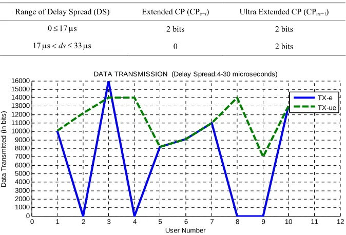
In Figures 6-8, TX-e and TX-ue represents transmission using extended and ultra extended CP respectively.
[image:6.595.51.540.386.465.2]In Figure 6, whereas user Number 3 transmitted 16 kilobits of data within the specified period using the ex- tended CP, the same user could only transmit 14 kilo- bits of data using the proposed ultra extended CP. This was possible because of the randomly generated channel
Table 4. Users, corresponding data and delay spreads.
Users 1 2 3 4 5 6 7 8 9 10
Data (Kbits) 10 12 16 15 8 9 11 14 7 13
Delay Spread (4 - 30 µs) 7 28 12 29 9 14 5 26 18 6
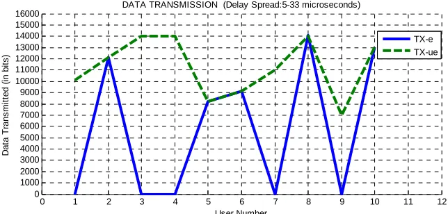
Delay Spread (5 - 33 µs) 26 5 30 21 11 12 24 13 19 9
[image:6.595.131.468.489.718.2]Delay Spread (10 - 20 µs) 13 14 17 16 12 15 20 10 19 18
Table 5. Delay spread and applicable transmitted bits.
Range of Delay Spread (DS) Extended CP (CPe−i) Ultra Extended CP (CPue−i)
0 17 s 2 bits 2 bits
17 s ds33 s 0 2 bits
0 1 2 3 4 5 6 7 8 9 10 11 12
0 1000 2000 3000 4000 5000 6000 7000 8000 9000 10000 11000 12000 13000 14000 15000 16000
DATA TRANSMISSION (Delay Spread:4-30 microseconds)
User Number
D
at
a
T
rans
m
it
te
d (i
n
bi
ts
)
TX-e TX-ue
0 1 2 3 4 5 6 7 8 9 10 11 12 0
1000 2000 3000 4000 5000 6000 7000 8000 9000 10000 11000 12000 13000 14000 15000 16000
DATA TRANSMISSION (Delay Spread:5-33 microseconds)
User Number
D
at
a T
rans
m
it
ted (
in
bi
ts
)
[image:7.595.138.460.88.242.2]TX-e TX-ue
Figure 7. Data transmission (delay spread: 5 - 33 µs).
0 1 2 3 4 5 6 7 8 9 10 11 12
0 1000 2000 3000 4000 5000 6000 7000 8000 9000 10000 11000 12000 13000 14000 15000
16000 DATA TRANSMISSION (Delay Spread:10-20 microseconds)
User Number
D
a
ta T
rans
m
it
te
d
(i
n
b
it
s
)
[image:7.595.139.461.275.428.2]TX-e TX-ue
Figure 8. Data transmission (delay spread: 10 - 20 µs).
delay spread of 12 µs for this particular user. Given the number of OFDM symbols per sub-frame, the transmis- sion of user Number 3 clearly favoured extended CP in- sertions. Conversely, user Number 8 with randomly gen- erated delay spread of 26 µs transmitted data using the proposed ultra extended CP while same user was unable to successfully transmit any bit using extended CP.
In Figure 7, the proposed ultra extended CP generally leads to higher data transmission than the existing ex- tended CP. Similar explanations go for results presented in Figure 8.
Upon completion of the simulation runs, the total bits transmitted by the ten users using the proposed ultra ex- tended CP was generally more than bits transmitted using the extended CP. For example, with the delay spread in the range 4 - 30 µs, 67 kilobits and 112 kilobits were transmitted by the ten users using the ultra extended and extended CP respectively. Similarly, with the delay spread in the range 5 - 33 µs, 56 kilobits and 112 kilobits were transmitted by the ten users using the extended and ultra extended CP respectively. Moreover, with the delay spread in the range 10 - 20 µs, 69 kilobits and 114 kilo- bits were transmitted by the ten users using the extended
and ultra extended CP respectively. Clearly, the proposed ultra extended CP provides a basis for wider transmission coverage as it can effectively address the problem of signal corruption due to longer delay spread.
It should be noted that longer CP may be beneficial in specific environments with extensive delay spread; for example in future telecommunication systems with large cells (or wider cell coverage area).
5. Conclusions
bility offered by the ultra extended CP to effectively transmit data when delay spread was beyond 16.67 µs. It was assumed that channel performance was not con- strained by noise but rather signal corruption as a result of channel time dispersion caused by longer delay spread. Furthermore, it was noted that longer CP may be benefi- cial in specific environments with extensive delay spread; for example in future telecommunication systems with large cells (or wider cell coverage area). Moreover, the energy needed for re-transmission of corrupted signals for the case of extended CP, caused by longer delay spreads, justifies the additional energy overhead of long- er CP. The efficacy of the proposed CP was tested under different scenarios via simulation. The results obtained showed that the proposed ultra extended CP can indeed be implemented in the design of future telecommunica- tion systems to address problems of signal corruption due to longer delay spread.
Future research work will focus on improvement of transmission efficiency.
REFERENCES
[1] A. M. Ajofoyinbo and K. O. Orolu, “Optimal Allocation of Radio Resource in Cellular LTE Downlink Based on Truncated Dynamic Programming under Uncertainty,”
International Journal of Communications, Network and Systems Sciences, Vol. 5, No. 2, 2012, pp. 111-120. http://dx.doi.org/10.4236/ijcns.2012.52015
[2] A. M. Ajofoyinbo and K. O. Orolu, “A Dynamic Pro- gramming Based Technique for Optimal Allocation of Radio Resource in Multi-User Cellular Long-Term Evo- lution (LTE) Downlink,” Recent Researches in Telecom- munications, Informatics, Electronics and Signal Proc- essing, 10th WSEAS International Conference on Tele- communications and Informatics (TELE-INFO 2011), Lanzarote, 27-29 May 2011, pp. 107-113.
[3] W. E. Osman and T. A. Rahman, “Optimal Guard Time Length Determination for Mobile WiMAX over Multi- path Fading Channel,” 8th WSEAS International Confer- ence on Applied Informatics and Communications
(AIC’08), Rhodes, 20-22 August 2008, pp. 255-260. [4] R. V. Nee and R. Prasad, “OFDM for Wireless Multime-
dia Communications,” Artech House, Boston, 2000. [5] T. S. Rappaport, S. Seidel and R. Singh, “900-MHz Mul-
tipath Propagation Measurement for US Digital Cellular Radiotelephone,” IEEE Transactions on Vehicular Tech- nology, Vol. 39, No. 2, 1990, pp. 132-139.
http://dx.doi.org/10.1109/25.54229
[6] S. Y. Siedel, T. S. Rappaport, S. Jain, S. Lord, M. L. Lord and R. Singh, “Path Loss, Scattering and Multipath Delay Statistics in Four European Cities for Digital Cellular and Microcellular Radiotelephone,” IEEE Transactions on Vehicular Technology, Vol. 40, No. 4, 1991, pp. 721-730. http://dx.doi.org/10.1109/25.108383
[7] T. S. Rappaport, “Characterisation of UHF Multipath Ra- dio Channels in Factory Buildings,” IEEE Transactions on Antennas and Propagation, Vol. 37, No. 8, 1989, pp. 1058-1069. http://dx.doi.org/10.1109/8.34144
[8] P. Tarasaki, K. Peng, X. Peng and F. Chin, “Design and Performance of Cyclic Delay Diversity in UWB-OFDM Systems,” EURASIP Journal on Wireless Communica- tions and Networking, Vol. 2008, 2008, Article ID: 541478.
[9] A. I. Siddiq, “Variable Length Cyclic Prefix OFDM Us- ing Multipath Delay Tracking,” Tikrit Journal of Elec- tronic Engineering Science, Vol. 18, No. 2, 2011, pp. 12- 21.
[10] M. Ghanbarisabagh, M. Ismail, M. Y. Alias and H. A. Abdul-Rashid, “Cyclic Prefix Reduction Technique for OFDM Systems over Multipath Fading Channels,” In- ternational Journal of Microwave and Optical Technol- ogy, Vol. 5, No. 4, 2010, pp. 251-257.
[11] B. Li, W. Zheng, S. Ren and J. Wu, “Optimal Selection of Cyclic Prefix and Sub-carrier for OFDM signal in Mobile Satellite Communications Channel,” Proceedings of the
2ndInternational Conference on Computer and Informa- tion Application (ICCIA 2012), Taiyuan, 8-9 December 2012, pp. 558-561.
[12] 3GPP Technical Specification TS 36.211v11.2, 02.2013. [13] 3GPP Technical Specification TS 36.300.v8.9.0 Release