Journal of Chemical and Pharmaceutical Research, 2014, 6(2):256-260
Research Article
CODEN(USA) : JCPRC5
ISSN : 0975-7384
Modeling and simulation in water turbine generator set systems
Tao Kuang
1and Shanhong Zhu
1, 21
School of Computer and Information Engineering, Xinxiang University, Henan, China
2
International School of Software, Wuhan University, Wuhan, China
____________________________________________________________________________________________
ABSTRACT
Water turbine generators are a nonlinear and time-varying complexity system, the electric power voltage and frequency should maintain the stable value to ensure safety power supply. The traditional PID control algorithm is difficult for accurate controlling, which causes along stabilizing time for the system. To solve the above problems and research on water turbine generator optimal control problem .the paper proposes a water turbine generator control method based on CMAC and PID. PID is used to realize feedback control and ensure that the system is stable and the system disturbances are reduced. Using CMAC feed forward control the control method speeds up the system response speed and reduces the overshoots, thus enhances the control accuracy modeling and Simulation results show that the compound CMAC and PID controller, compared with the conventional PID controller, improves the real-time performance, enhances the stability of the system, which ensures better control effects becomes more smooth and faster in adjusting.
Key words: Water turbine generator set; CMAC neural network; Nonlinear; PID compound controller
_____________________________________________________________________________________________
INTRODUCTION
The hydroelectric generating set transfer the energy of moving water into electrical energy to provide to the user, not only for safe and reliable power supply, but also requires power to maintain the voltage and frequency of electric energy near the rating of a certain range, otherwise it will directly affect the quality of power supply products [1, 2].Characteristics of the turbine regulating system with the generator frequency change and adjust accordingly, PID controller has the advantages of simple structure, high reliability, so the turbine regulating system parameters adopt the PID control method [3].the basic control idea of PID is to integrate the three parameters of bias the proportion coefficient, integral and differential time in order to get a relatively ideal control effect, so the PID parameter adjustment is a key problem in PID control [4].
Traditional PID turbine regulating system
[image:2.595.183.439.119.260.2]Speed is still widely used at present, the hydroelectric generating set is a PID control regulation, and its structure is shown in figure 1
Fig 1 PID control regulatory system
The Figure 1, where X is a symbol for the relative value of turbine units speed deviation; C represents the machine control speed instructions; Y is noted as relative value in guide vane relay trip changes; Ty is the time constant the
relay device response t; Kp, Ki, Kd, respectively are the three PID Parameters: the proportion, integral and
differential gain; Tnis actual differential gain, and S the Laplace operator. The structure of the turbine regulating
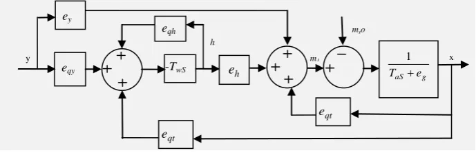
system is shown in figure 2.
Figure 2 water turbine regulating system
In Figure 2, the ex, eh, ey, eqx, eqh and eqy represent turbine transmission coefficient respectively; Tw, T respectively are water inertial time constant in pressure water system, and the set inertial time constant. MgO is noted as load disturbance. The turbine speed deviation and the main relay schedule Transfer function can be expressed in a form:
S
T
S
T
S
K
s
K
K
s
G
y n
d i
p
+
+
+
+
+
−
=
1
1
)
1
(
)
(
(1)The transfer function of type pressure diversion system by using the rigid water hammer model can be expressed in a form:
s
T
s
G
t(
)
=
−
w (2) The turbine data model with minor fluctuation is as follows:
+
+
=
+
+
=
h
e
y
e
x
e
q
h
e
y
e
x
e
m
qh qy qx
h y x t
(3)
The mathematical model of first-order generator can be expressed as follows:
s
e
s
T
s
G
+
=
1
)
(
(4)ey
eqy
g aS e
T +
1
mso
y x
h
e
qt
e
qt
e -TwS eqh
m1
h
p
K
s Ki
1
+
ns ds
T K
1 1
+
ys
T
y
[image:2.595.136.481.357.468.2]The traditional PID controller constants as Kp, Ti, Td are fixed, but hydro-generator mechanical control System has the characteristics of nonlinear, time varying, unsteady, so traditional PID has low control precision. CMAC neural network can adjust dynamically by algorithm learning has the ability of information classification storage, suitable for the operation of real-time nonlinear system [8].
CMAC - PID control system design of hydroelectric generating set The working principle of CMAC neural network
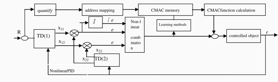
[image:3.595.71.542.200.366.2]CMAC neural network is the cerebellum model joint controller which has the associative memory and the ability to multidimensional nonlinear function mapping nonlinear approximation[9], and the principle structure is shown in figure 3.
Fig. 3 principle structure of CMAC
Due to CMAC is a kind of neural network based on local learning which has fast learning speed and is suitable for real-time control [10]. CMAC neural network is put forward in this paper Combined with PID compound control strategy and control system for hydroelectric generating set System. The method of designing the CMAC model is divided into the following three steps:
1.Quantification: the concept mapping. delimiting the N input space in the input layer to make the network's input landing to N grid base in a hypercube sheet .Network interface layer is composed of several interval, for anyone to lose In only a few range of output for a non-zero value, the interval number is called parameter C. Its influence on grid internal network output decides the size of the region.
2.Address mapping: the actual mapping. The algorithm is the remainder method, namely mapping the input samples to the address of the memory, dividing the number of the sample by a Number, using the remainder as actual memory address values [11].
3.CMAC function calculation: namely the CMAC output. The corresponding weights of input mapping are saved to the actual storage as C, The actual storage unit weighted sum as C is the output of CMAC.
3. 2 CMAC and PID compound control structure
CMAC and PID compound control structure diagram is shown in figure 4, the system is accomplished by parallel control of CMAC and PID to realize feed forward and feedback control, especially the use of CMAC feed forward control realize the inverse dynamic model of hydroelectric generating set; Using nonlinear PID feedback control ensure convergence of the system.
CMAC and PID compound control
CMAC neural network adopts a mentor learning algorithm, when at the end of each control cycle, the CMAC output UN (k) and total control input u (k) are compared, and the weights of the corresponding correction, and then to the learning process. Learning aim is to make total minimum error between the control input u (k) and CMAC output UN (k) [12]. After CMAC neural network learning, making the compound control system of the total output produced by CMAC control. CMAC composite system with PID control algorithm is as follows:
)
(
)
(
)
(
k
u
k
u
k
u
=
n+
p (5)U Inputvector
Input vector AP(w)
ACScattered coding
∑
==
c j j jn
k
w
a
u
1)
(
(6) [image:4.595.71.546.154.294.2]Where wj is the weight vector; Aj is binary choice vector; C is CMAC neural network generalization of parameters; The Un (k) is the output of the CMAC neural network; the up (k) said the PID output generated.
Fig .4 CMAC and PID compound control structure
CMAC neural network mapping process is the concept that the input space S in the interval [Vmin, Vmax] is divided into N+2c quantization interval:
≤
+
+
=
∆
+
=
≥
+ + + + + − max 2 2 1 1 min 2 1,...
,
,...,
1
,
,...,
,
S
V
v
v
N
c
c
j
v
v
v
S
v
v
v
c N c N c N j j j c (7)The actual mapping method in CMAC neural network is deduced as follows:
∈
=
+
+
=
+0
,...,
1
],
,
[
,
1
S
v
v
i
c
c
N
a
j j i i c (8)The adjustment of the CMAC neural network can be written as:
c
k
u
k
u
k
E
n1
))
(
)
(
(
2
1
)
(
=
−
2×
(9)j p j n
a
c
k
u
a
c
k
u
k
u
w
k
E
k
w
(
)
η
(
)
=
η
(
)
−
(
)
=
η
(
)
∂
∂
=
∆
(10)))
1
(
)
(
(
)
(
)
1
(
)
(
k
=
w
k
−
+
∆
w
k
+
w
k
−
w
k
−
w
β
(11)
where (0, 1) is the network learning rate; [0, 1] is the amount of inertia
When the system is running, W = 0, the Un = 0, the Up = 0, system is controlled by the conventional controller.
Through the study of CMAC, the output of the PID Up(k)) gradually decline to zero, CMAC control output of the Un
(k) controller increasingly impend total output u (k).
CONCLUSION
Due to the complexity of the turbine generator set adjustment object, the traditional effect on PID control is not optimal [13]. This paper puts forward a new kind of hydroelectric generating set intelligent CMAC-PID compound controller, give full play to the advantages of both the hydro-generator intelligent control and PID control, control
η
β
quantify
TD(1) controlled object r
R x11 Non-l inear comb inatio n Learning methods TD(2) ∫ e
address mapping CMAC memory CMACfunction calculation
parameters online. The simulation results show that CMAC-PID compound control compared with conventional PID control, adjust more smoothly, and adjust the speed faster. When the operation condition of the system parameter change or disturb, CMAC-PID control effect is much higher than the traditional PID control, the hydro-generator frequency can be stabilized faster, the CMAC-PID compound controller improves the adaptability and robustness of hydroelectric generating set , open up a new way of application online control for hydro-generator units .
Acknowledgment
This project is supported by HeNan Department of frontier and Foundation and ackling-key project of Henan Department in China (Grant No. 132300410405 and No.1333020005).
REFERENCES
[1] J. Tanura, T. Sasaki, S. Ishikaya,et al. IEEE Transactions on Energy Conversion. 250~256. Vol.4 No.2January
1989
[2] B.M.Bird. IEEE Proc. 10~16 .Vol.113 No.6 1966. [3] F.J.Brady. IEEE.Trans. Vol.PAS-103 No.4 1984.798~803
[4] M.S.Vicatos,J.A.Teqapoulos. IEEE Transactions on Energy Conversion.80~88 .No.6 1991.
[5] Krzeminski Z. Control System of Doubly-Fed Induction Machine Based on Multiscalar Model. IFAC 11th World Congress.Tallin.185~190.1990.
[6] Arsudis D,Vollstedt W. Sensor-less Power Control of a Doubly-Fed AC Machine with Nearly Sinusoidal Currents. EPE.Conference. Aachen.876~881
[7] Eel-Hwan, Jae-Hong Kim. ICEMS’2001.747~750.2001.
[8] Lansberry J. E. and Wozniak L. IEEE Trans. On Energy conversion.1992 7(14)5.623~628 [9] Yifan Tang and Longya Xu, IEEE Trans. on Power Electronics.472~478.Vol.10,No.4,July1995
[10] B.Hopfensperger and R. A. Lakin, IEE Proc.-Electr. Power Application. 597~605 Vol.146. No.6, November
1999.
[11] B.Hopfensperger. IEE Proc. Electr. Power Appl..241~250 Vol. 147,No. 4, July 2000.
[12] J.E.Lansberry, L.Wozniak. IEEE Trans. on Energy Conversion.179~183 Vol.9, No.1, 1994.
![figure 3. multidimensional nonlinear function mapping nonlinear approximation[9], and the principle structure is shown in](https://thumb-us.123doks.com/thumbv2/123dok_us/8773744.900248/3.595.71.542.200.366/multidimensional-nonlinear-function-mapping-nonlinear-approximation-principle-structure.webp)