VLSI Implementation of Scalable Encryption Algorithm
for Different Text and Processor Size
T.Kalpana
Assistant Professor SR. Engineering CollegeWarangal, AP, India
K.Srinivas
Assistant Professor JNTUH College of EngineeringKarimnagar, AP,India.
ABSTRACT
The Efficiency of present symmetric encryption algorithms mainly depends on implementation cost and resulting performances. Present symmetric encryption, like the Advanced Encryption Standard (AES) rather focus on finding a good tradeoff between cost, security and performances. Some present symmetric encryption algorithms are targeted for software implementations and shows significant efficiency improvements on these platforms compared to other algorithms. From these algorithms, consider a general context where we have very limited processing resources (e.g. a small processor). It yields design criteria such as: low memory requirements, small code size, limited instruction set, i.e. Scalable Encryption Algorithm (SEA).
For this purpose, loop architecture of the block cipher is presented.
The total modules of SEA written in VHDL coding, the simulation and synthesis results are verified by the Virtex-4 of Xilinx 9.1i. This paper also carefully describes the implementation details and corresponding area requirements
General Terms
Security, AlgorithmsKeywords
Block cipher, SEA.1.
INTRODUCTION
This Scalable Encryption Algorithm (SEA) has been recently attracting increased attention. The ability to use parametric in the Plaintext, key and processor sizes and it was initially designed as a low-cost encryption/authentication are two main reasons why, Scalable encryption algorithm is becoming more popular. They are considered to be particularly suitable for implementation on platforms with constrained storage and fast specifications. Scalable Encryption Algorithm (SEA) follows unusual design principle for flexibility proposes. It is parametric in the text, key and processor size. Many algorithms behave differently on different platforms (e.g. 8-bit or 32-bit processors). It provides efficient combination of encryption and decryption. SEA is mostly used in embedded applications such as software implementations in controllers, smart cards, or processors.
The security attacks [1][2] on scalable encryption algorithm were easily evaluated compare to other algorithms like Tiny Encryption Algorithm TEA [3] and Yuval’s proposal [4].
The security of the SEA being adapted in function of its key size, SEA has the efficient combination of encryption and decryption or the ability to derive keys. SEA is implemented in embedded applications such as building infrastructures present a significant opportunity and challenge for new
cryptosystems [5] [6]. Embedded software implementation of SEA has been done. The advantages of embedded software implementation include ease of use, ease of upgrade, portability, low development cost and flexibility. There main disadvantages on the other hand, are their lower performance and limited ability to protect private keys from compared to hardware implementations [7][8].Software implementations can easily be achieved on micro processor. However, they would be too slow for critical time applications
In the rest of the paper we first describe the algorithm specifications then we describe the architecture implementation and results.
2.
ALGORITHM DESCRIPTION
Scalable Encryption Algorithm (SEA) is a symmetric algorithm [9] [10], which works on the concept of Block cipher. In SEA same keys are used for both encryption and decryption.
The complete description of the scalable encryption algorithm is emphasizing its basic operation starting with the important parameters and afterwards follows the round and key round description.
2.1. Parameters and Definitions
SEAn,b operates on various text, key, and word sizes. It is based on a Feistel structure [11] [12] with a variable number of rounds, and is defined with respect to the following parameters:
n- Plaintext size, key size;
b- Processor (or word) size;
2
n
n
b
b
Number of words per Feistel branch;nr
Number of block cipher rounds.As an only constraint, it is required that n is a multiple of 6b. For example, using an 4-bit processor, we can derive 48, 96, 144, . . . -bit block ciphers, respectively denoted as SEA48,4, SEA96,4, SEA144,4, ...
Let x be a
2
n
-bit vector. Consider the following two
representations. Bit representation:
1 ...
2
1
0
2
n
x
b
x
x
x
x
(2.1)Word representation:
x
w
x
n
1
x
n
2
...
x x x
2 1 0
b
b
2.2 Basic Operations
Due to its simplicity constraints, SEAn,b is based on a limited number of elementary operations (selected for their availability in any processing device) denoted as follows:
(1) Bitwise XOR(
) (2) Substitution box S (3) Word rotation R and inverse word rotation R−1, (4) Bit rotation r (5) Addition mod ⊞These operations are formally defined as follows:
2.2.1 Bitwise XOR(
):
In Feistel cipher structures bit-by-bit XOR (modulo-2 sum) operation is used in every round for providing secrecy of data The XOR operation is used in this algorithm and it is defined
in equation
2
2
2
2
2
2
n
n
n
Z
Z
Z
;
,
, 0
1
2
n
x y
z
x
y
z i
x i
y i
i
(2.3)
2.2.2 Substitution Box S:
In cryptography, S-boxes constitute a basic component of symmetric key algorithms. In block ciphers, they are typically used and are difficult to understand the relationship between the plaintext and the cipher text. Non-linear and non-correlated S-boxes are the most secure with respect to linear and differential cryptanalysis. In this encryption algorithm, the encryption and decryption blocks are implemented with 4-bit S-Box.
SEAn,b uses the 4-bit S-Box and is shown in table I.
= {0, 9, A, B, 4, D, F, E, 8, 5, 2, 7, 1, 3, 6, C},
Table1. 4-Bits Box
For efficiency purposes, it is applied bitwise to any set of four words of data using the following recursive definition shown in equation.
:
:
2
2
n
n
b
b
S Z
Z
x
x
S x
b
b
3
3 1
3 2
3 ,
x
i
x
i
x
i
x
i
3 1
3 2
3 3
3 1
x
i
x
i
x
i
x
i
3 2 3 3 3 3 2
x i x ix i x i
, 0
1,
3 3
3 1
3
3 3
3
n
b
x
i
x
i
x
i
x
i
i
(2.4)
Where ∧ and ∨ respectively represent the bitwise AND and OR.
2.2.3 Word rotation R:
The word rotation(R) and inverse word rotation(R-1) implementations are used in SEA. It improves the efficiency of encryption and decryption. In the word rotation, a stream of bits is divided into blocks of data. Occupying of bits in each block is dependent on the processor (or word) size. The rotations are performed between blocks. According to the equation 2.5 left shift is performed between the blocks. In inverse word rotation right shift is performed between the blocks.
The word rotation R, defined on nb-word vectors.
: : 1 , 0 2
2 2
nb nb
R Z b Z b x y R x yi xi i nb
1
0
y
xn
b
(2.5)
2.2.4 Bit rotation r:
The bit rotation implementation is used in SEA. It improves the efficiency and secrecy of encryption and decryption. In the bit rotation, a stream of bits is divided into blocks of data. Occupying of bits in each block is dependent on the processor (or word) size. The rotations are performed between bits in a block. The bit rotation equation2.6 The bit rotation r, defined on nb-word vectors.
:
:
3
3
2
2
n
b
n
b
r Z
b
Z
b
x
y
r x
y
i
x
i
>>>1
3 1
3 1
y
i
x
i
3 2
3 2
y
i
x
i
<<<1, 0
i
n
3
b
1
(2.6)Where >>> and <<< represent the cyclic right and left shifts inside a word.
2.2.5 Addition mod
⊞
:
Now a day’s modulo addition is widely used in encryption algorithms. The addition mod implementation is used in SEA. It is a mathematical function and it performs carry skipped addition. It has some advantages over bitwise XOR, these are
1. Improvement of the diffusion process,
2. Improvement of non-linearity,
3. Same cost/speed as the bitwise XOR in most processors,
4. Necessity to avoid structural attacks.
The mod 2b addition is defined on in equation 2.7
C. The Round and Key Round
⊞:
:
: ,
2
2
n
b
n
b
Z
b
Z
b
x y
z
= x
⊞
y
, 0 1
Zi XiYi i nb (2.7) 00 91 A2 B3
44 D5 F6 E7
88 59 210 711
Based on the previous definitions, the encrypt round FE, decrypt round FD and key round FK are pictured in Fig. 2.1
R-1 R
r S
Ki
R r S
Ci Li Ri KLi KRi
[image:3.595.70.272.101.238.2]Li+1 Ri+1 KLi+1 KRi+1
Figure.2.1: A view of Encrypt/Decrypt round and key round
The security of this algorithm mainly depends on number of rounds. In key round, according to equation 2.8, the round
input is split into its left and right halves say
KLi
andKRi
for the input to round i. In this the
KRi
is first added bit-by-bit modulo 2 addition to (constant values means 1,2,3…etc) then the resulted data goes into substitution box(S-Box) and performed non-linear substitutions then a bit(r) type and word(R) type rotations performed on resulted data of S-Box,then it xored with
KLi
and the resultant new data is1
KL
i
and
KRi
is directly taken asKRi1.The left and right halvesare then “swapped” to produce the left half
KLi
and righthalf
KRi
of the output of round i as1
KL
i
KR
i
and1
KR
i
KL
i
.In encryption round, according to equation 2.10, the round
input is split into its left and right halves say
Li
andRi
forthe input to round i. In this the
Ri
is first added bit-by-bitmodulo 2 to
Ki
(produced key from key round) then the resulted data goes into substitution box(S-Box) and performed non-linear substitutions then a bit(r) type rotations performed on resulted data of S-Box, then it x-ored with word rotationperformed
Li
and the resultant new data is1
L
i
andRi
isdirectly taken as
R
i1.The left and right halves are then “swapped” to produce the left halfLi
and right halfRi
of theoutput of round
i
as1
L
i
R
i
And1
R
i
L
i
The equation 2.11 explains decryption round which is similar to the encryption round, the only difference is instead of
considering word rotation on
Li
, and an inverse word rotation is performed on output of xor.It is defined as the functions
2
2
:
2 /2
2 /2
2 /2
F Z
n
Z
n
Z
n
Such that
L
Ri
(2.8)[ 1; 1] ( , , ) 1
( ( ( )))
1
Li Ri FD L R Ki i i Ri
R L r S Ri i Ki
1
L
i
Ri
(2.9)[
1
,
1
]
(
,
,
)
1
( ( (
)))
KL
i
KR
i
F
K
KL KR C
i
i
i
KR
i
KL R r S KR
i
i
C
i
1
KL
i
KRi
(2.10)3.
IMPLEMENTATION OF SEA
3.1 Architecture of Scalable Encryption
Algorithm (SEA)
The VLSI architecture for the implementation of the Scalable Encryption Algorithm consists of the three main components, key scheduling, Encryption and Decryption. The implementation mainly consists of 8-bit processor size, ten no of rounds, key and plaintext of 48-bits size.
3.1.1
Encryption Block
In the implementation entire design has been divided in to various modules given below.
Key schedule block,
Single round of Key schedule block, Encryption block,
Single round of Encryption block.
3.1.1.1 Key schedule block
Key input (48-Bit)
Round 1
. .
.
Round 10 Round 9 Round 2
K1 (48-Bit) K2 (48-Bit)
K9 (48-Bit) K10 (48-Bit)
Figure.3.1: Key schedules for ten rounds
Key schedule has been implemented as a module, which is used in encryption block to provide keys for encryption of plaintext. Key scheduling is implemented for ten rounds. The key schedule block takes 48-bit key as input and it produce ten subkeys of length 48-bit. Each subkey is used for each round of encryption and used for each round of decryption in reverse order. The simple architecture for key schedule as shown in Fig.3.1
3.1.1.2 Single Round of Key schedule block
[image:3.595.318.514.421.614.2]bit half and right 24-bit. The right 24-bit of key is performed modulo addition with constants like 1, 2, 3, 4….etc (represented in terms of bits). The usage of number of constant values is dependent on number of rounds. Round constant is changed by key rounds. By using this round constant, reduce the related key attacks [13].
24-Bit
Output i(48-Bit) 24-Bit
Right i
Right i Const i
Substitution Box
Bit Rotation Left i
Word Rotation
Left i Right i
Left i Right i
24-Bit 24-Bit
24-Bit
24-Bit 24-Bit Input i(48-Bit)
XOR
24-Bit 24-Bit 24-Bit
[image:4.595.331.527.117.334.2]24-Bit
Figure.3.2: Single round of key schedule
3.1.1.3 Encryption block
Encryption block has been implemented as a module. All other modules like modulo addition, S-Box, bit rotation, word rotation are internal modules of encryption block.. Encryption is implemented for ten rounds. The encryption block takes 48-bit as input key and 48-bit as plaintext. The encryption block and key schedule blocks are implemented for ten rounds.
Plain Text (48-Bit)
Cipher Text (48-Bit) Key (48-Bit)
K
e
y
G
e
n
e
ra
ti
o
n
B
lo
c
k
KL1 SEA Round 1
. .
.
KR1 K1 (48-Bit)
KR1 KL2 KR2
KL10 KR10 KL6 KR6 KL7 KR7 KL5 KR5
SEA Round 10 SEA Round 7 SEA Round 6 SEA Round 5 SEA Round 2
. .
. . . .
. .
.
KR2
KR5
KL6
KL7
KL10 K2 (48-Bit)
K5 (48-Bit)
K6 (48-Bit)
K7 (48-Bit)
K10 (48-Bit)
Figure.3.3: Architecture of Encryption Block
Each subkey from original key is generated in key schedule and used in parallel for every encryption round. For the First five rounds of encryption, the right half of first five subkeys are used for encryption process and for next five rounds of encryption the left half of next five subkeys are used for encryption process is shown in Fig.3.3.
In the architecture of encryption block, key generation block takes 48-bit as input key “2B7E151628AE” and it produce ten sub keys. Key left 24-bits and key right 24-bits are left and right parts of the key. Right 24-bits of first five subkeys are used for the first half of encryption. Light 24-bits of next five subkeys are used for the next half of encryption. Required
ciphertext is produced after completion of encryption process with key and plaintext “212223242526”.
3.1.1.4 Single Round of Encryption block
Output i(48-Bit) 24-Bit
Right i
Key i Right i
Substitution Box
Bit Rotation Left i
Left i Right i
Left i Right i
24-Bit 24-Bit
24-Bit 24-Bit
24-Bit Input i(48-Bit)
XOR
Word Rotation
24-Bit
24-Bit
[image:4.595.74.265.141.331.2]24-Bit 24-Bit 24-Bit
Figure.3.4: Single round architecture of Encryption Block
Single round architecture of encryption block is same as single round of key schedule block. The single round implementation structure as shown in Fig.3.4 The working principle internal blocks of single round of encryption is same as single round of key schedule block.
In the implementation, entire design is divided in to various modules given below.
Decryption block,
Single round of Decryption block, Inverse word rotation.
3.1.1.4.1 Decryption block
Decryption block has been implemented as a module. All other modules like modulo addition, S-Box, bit rotation, inverse word rotation are internal modules of decryption block. The Feistel structure ensures that decryption and encryption are very similar processes but the only difference is that the subkeys are applied in the reverse order when decrypting.
[image:4.595.76.283.448.614.2]Key (48-Bit)
Plain Text (48-Bit) Cipher Text (48-Bit)
K ey G en er at io n B lo ck
KL10 Decryption Round 1
. .
.
KL10 K10 (48-Bit) KR10 KL9 KR9 KL1 KR1 KL5 KR5 KL4 KR4 KL6 KR6Decryption Round 10 Decryption Round 7 Decryption Round 6 Decryption Round 5 Decryption Round 2
. .
.
. .
.
. .
.
KL9 KL6 KR5 KR4 KL1 K9 (48-Bit) K6 (48-Bit) K5 (48-Bit) K4 (48-Bit) K1 (48-Bit)Figure.3.5: Architecture of Decryption block
In the architecture of decryption block, key schedule block takes 48-bit as input key “2B7E151628AE” and it produce ten sub keys. Key left 24-bits and key right 24-bits are left and right parts of the key. Right 24-bits of first five subkeys are used for the last half of decryption process. Left 24-bits of next five subkeys are used for the first half of decryption process. Required plaintext is produced after completion of decryption process with key and ciphertext “EC74983B2526”.
3.1.1.4.2 Single round of Decryption block
Output i(48-Bit) 24-Bit
Right i
Key i Right
Substitution Box
Bit Rotation Left i
Inverse word rotation
Left i Right i
Left i Right i 24-Bit 24-Bit 24-Bit 24-Bit 24-Bit 24-Bit 24-Bit Input i(48-Bit) XOR Word Rotation 24-Bit
Figure.3.6: Single round architecture of Decryption
Single round architecture of decryption block is same as single round of encryption block. The only difference is, in single round decryption block the ciphertext is splits into two halves say left and right block then the inverse word rotation performed on resulted output of xor. The single round implementation decryption block structure as shown in Fig.3.6. The working principle internal blocks of single round of decryption is same as single round of encryption block.
3.1.1.4.3 Inverse word rotation.
In this inverse word rotation circular right shift is performed between blocks (words).
4.
RESULTS
The netlist output is made available in various netlist formats including VHDL. Such a description can be simulated and its simulation is referred as Post Synthesis simulation. Timing issues, Determination of proper clock Frequency and race and hazard considerations can only be checked by a post synthesis
The netlist output is made available in various netlist formats including VHDL. Such a description can be simulated and its simulation is referred as Post Synthesis simulation. Timing issues, Determination of proper clock Frequency and race and hazard considerations can only be checked by a post synthesis simulation run after a design is synthesized.
The Post-Route simulation waveform for Key schedule of 48-bit is shown in Fig.4.1. It can be seen that input key is“2B7E151628AE” is applied to key schedule, it provides ten subkeys of 48-bit.
The Post-Route simulation waveform for Encryption Block of 48-bit is shown in Fig.4.2. It can be seen that Plaintext is “212223242526” is applied to encryption block. Ciphertext is “EC7498382526” provides after ten rounds encryption process with use of subkeys.
The Post-Route simulation waveform for Decryption of 48-bit is shown in Fig.4.3. It can be seen that Ciphertext is “EC7498382526” is applied to decryption block. Plaintext is “212223242526” provides after ten rounds decryption process with use of subkeys in reverse order to encryption.
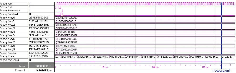
The Post-Route simulation waveform for Encryption and Decryption is shown in the Fig.4.4. From the Fig.4.4 the encryption and decryption is implementing for ten rounds. The key scheduling block is used to generate ten subkeys which are used for encryption and decryption of ten rounds. In the encryption process, the subkeys with the Plaintext “212223242526” are used for the generation of the Cipher text “EC74983B2526”, which occurs after ten rounds of encryption.
The Ciphertext of the encryption process is given as the input to the decryption process for the regeneration of the original Plaintext “212223242526”. The keys used in decryption process are in reverse order to the encryption process.
Table2. Implementation results for sea with different n and b parameters
Figure.4.1: Post-Route Simulation waveform for Key schedule
Figure.4.2: Post-Route Simulation waveform for Encryption Block
Figure.4.3: Post-Route Simulation waveform for Decryption Block
[image:6.595.55.551.422.576.2]The implemented results for SEA with different n and b parameters are presented in Table5.3, where the area requirements (in slices) and the working frequency are presented in table. The obtained working frequencies are very close for all implementations. For set of parameters increasing processor (b) size for a given plaintext (n) generally decreases the area requirements in slices. The examination from the table is, the processor size is not a limiting factor for the working frequency, increasing the word size leads to the most efficient implementation for area.
5.
CONCLUSION
In this paper, the VLSI architecture of Scalable Encryption Algorithm provides flexibility to implement it for various sets of parameters like plaintext, key size and bus size, but the plaintext and key size must be same size. The VLSI architecture of SEA is designed using VHDL and is simulated in Xilinx 9.1i or Modelsim6.0.This paper presented FPGA implementations of a scalable encryption algorithm for various sets of parameters. The presented parametric architecture allows keeping the flexibility of the algorithm by taking advantage of generic VHDL coding. It executes one round per clock cycle, computes the round and the key round in parallel and supports both encryption and decryption at a minimal cost. Compared to other recent block ciphers, SEA exhibits a very small area utilization that comes at the cost of a reduced throughput. Consequently, it can be considered as an interesting alternative for constrained environments.
6.
REFERENCES
[1] Rao, K.D.; Gangadhar, C. VLSI realization of a secure cryptosystem for image encryption and decryption Communications and Signal Processing (ICCSP), 2011 IEEE International Conference 2011 , Page(s): 543 - 547 [2] Dam J. Elbirt, “ReconFig.urable Computing for
Symmetric-Key Algorithms”.
[3] D.J. Wheeler, R. Needham, TEA, a Tiny Encryption Algorithm, in the proceedings of FSE 1994, Lecture Notes in Computer Science, volume 1008, pp 363-366, Leuven, Belgium, December 1994, Springer-Verlag. [4] G. Yuval, Reinventing the Travois: Encryption/MAC in
30 ROM Bytes, in the proceedings of FSE 1997, Lecture Notes in Computer Science, volume 1267, pp 205-209, Haifa, Israel,January 1997, Springer-Verlag.
[5] A. Menezes, P. van, “Handbook of Applied Cryptography”.
[6] Hongyong Jia; Yue Chen; Xiuqing Mao; Ruiyu Douv Efficient and scalable multicast key management using attribute based encryptionv Information Theory and Information Security (ICITIS), 2010 IEEE International Conference 2010 , Page(s): 426 - 429
[7] B. Schneier, “Applied Cryptography” John Wiley & Sons Inc., New York, New York, USA, 2nd edition, 1996.
[8] R. Doud. Hardware Crypto Solutions Boost VPN. Electronic Engineering Times, (1056):57{64, April 12 1999.
[9] H. Feistel. Cryptography and Computer Privacy. Scientific American, 228(5):15-23, May 1973.
[10]F.-X. Standaert, G. Piret, N. Gershenfeld, and J.-J. Quisquater,“Sea: A scalable encryption algorithm for small embedded applications,” in Proc. CARDIS, 2006, pp. 222–236.
[11]F.-X. Standaert, G. Piret, G. Rouvroy, J.-J. Quisquater, J.-D.Legat, ICEBERG an Involutional Cipher Efficient for Block Encryption in ReconFig.urable Hardware, in the proceedings of FSE 2004, Lecture Notes in Computer Science, vol 3017, pp 279-299, New Delhi, India, February 2004, Springer-Verlag.
[12]E. Biham, New types of cryptanalytic attacks using related keys,Journal of Cryptology, vol 7, num 4, pp 229-246, Fall 1994, Springer Verlag
[13]Jiang Bian; Seker, R.; Topaloglu, U.; Bayrak, C. A scalable Role-based Group Key Agreement and Role Identification mechanism Systems Conference (SysCon), 2011 IEEE International 2011 , Page(s): 278 – 281
7.
AUTHORS PROFILE
T.Kalpana received the B.Tech. degree in electronics and
instrumentation engineering from Kakatiya Institute of Technology and Science, Warangal , Kakatiya University, Warangal, India, in 2001, the M.Tech. Degree in Digital systems and Computer Electronics, Jawaharlal Nehru Technological University Hyderabad in 2010, Currently, she is an Assistant Professor in Electronics and Communication Engineering Department, SR Engineering College (Autonomous), Warangal, AP, India. Her fields of interest include signal processing and communication systems.
K.Srinivas received the B.E. degree in electrical and