Proceedings of EnCon2010
3rd Engineering Conference on Advancement in Mechanical
and Manufacturing for Sustainable Environment April 14-16, 2010, K
uching, Sarawak, Malaysia
Smart Parking Guidance System
Marlia binti Morsin, Lim Hwei Hwa , Abdul Majeed bin Zulkipli and Tasiransurini Ab. Rahman
Abstract— With the increasing growth of automotive industrial in our world, the demand for the vacant parking is expected to grow rapidly in near future. By using the technology which is available nowadays, intelligent parking system is needed to reduce the problems faced by the vehicle owner. The design of Parking Guidance System using VHDL is used to guide the driver to the vacant space in a short time. With the vacant spaces display on the entrance gate, the driver is able to know is there any vacant space in the building and driver will be guided to the vacant space by the display in the building. After this system is designed, it will be implemented to Altera DE II board by using the Quartus II software. In this Parking Guidance System, it contained counter system, censoring system and display system. The counter system is used to count the total vacant space which is available and counting the total vehicle in the building. Light detector resistor being used in the censoring system to detect either any vacant space was parked by any vehicle and the data will be sending to the main processor in Altera DE II board for process. The display system is used to display all the data which was sent by the processor in the main entrance of the parking building and specified location to guide the driver to the vacant space. A programming system was wrote in VHDL coded and being applied in the system by using the Altera DE II board, the Altera’s Quartus-II being used as the interface between these hardware for downloading purpose. The process of the programming will drive the output to be display in the display components. It will be shown by the seven segment display and the LED display which will able to drive the consumer to the located vacant space.
Keywords: Parking Guidance System, VHDL, Altera DE II Board
I. INTRODUCTION
N recent years, the number of cars on the road is increasing while parking spaces are becoming increasingly
scarce.
Marlia Morsin, Abdul Majeed Zulkipli and Tasiransurini Ab. Rahman are with Faculty of Electrical and Electronic Engineering, University of Tun Hussein Onn Malaysia, 86400 Parit Raja, Batu Pahat, Johor, Malaysia,
Tel:07-4537524,Fax:07-4536060, ({e-mail: marlia, majeed and
Lim Hwei Hwa is a B.Eng’s student at University of Tun Hussein Onn Malaysia, 86400 Parit Raja, Batu Pahat, Johor, Malaysia.
There is a need for them to find out any vacant spaces to park their vehicle without wasting a lot of time, and petrol to
find a vacant space. Certain of the parking garage building only provide the system which shown to the driver the total amount of vacant spaces in a parking garage building. This may make the user need to take much time to find out the vacant space without knowing the location.
II. SYSTEM DESCRIPTION
With the increasing growth of automotive industry and the demand for intelligent parking service is expected to grow rapidly in the near future. The Parking Guidance System will provide the automatic management of parking lots by accurate monitoring and making that information available to customers and facility administrators. This product is designed to be able to detect the vacant spaces in parking garage and guide the driver to the vacant space without using any manpower as well. The Parking Guidance System using VHDL is also able to display the total number of vacant spaces and the location of the vacant spaces.
All of these will be fully controlled by the Altera’s DE II board. Altera’s Development and Education (DE II) Board have been developed to provide an ideal learning about digital logic and computer organization in a laboratory setting [1]. Figure 1 shows the DE II board which plays as a main role in this project.
DE II board is a central processor unit to control all the data and display all the output as well. The number of vacant spaces will be displayed together with the location of the vacant spaces by using Altera’s DE II board. Altera’s Quartus II was used as the interface for coding and programming. It was used to code in VHDL language and downloads it into the DE II board for the censorings purpose and also counting the vacant spaces. The prototype is created and the detection circuit is designed using the light detector sensor. This external circuit will be connected to the DE II board and the data will be sent through cable data and being proceeded by the Altera’s DE II board.
Figure 1 - Altera Development and Education (DE II) board
[image:2.595.77.267.286.542.2]Figure 2 depicts the overall process flow for Smart Parking Guidance System’s operation.
Figure 2 - The process flow of the Parking Guidance System
The process of the system begin when a vehicle drive into the car park site. The vacant space counter of the Parking Guidance System will start counting when a ballot ticket was taken by the driver at the entrance gate. Once the ballot ticket button being press, the counter will start to be functioned and it will counter for in and out of the vehicle. The vacant space counter and display (Display A) which located at the main entrance of the site will show the total vacant spaces as information to the vehicle driver before the vehicle is drive into the site.
When the vehicle passed by the parking ballot machine, vacant space locator display (Display B) used to display the vacant spaces location by showing the vacant space lot number to the driver and show the direction arrow pointer to guide the driver to the vacant spaces precisely. The vacant space locator display not only placed near to the entrance of the car park site, but it also placed at certain selected places
for display the currently information to the user of the car park site. The vacant spaces counter is coded in VHDL code by using the Altera’s Quartus II and process through the Altera’s DE II board. The counter program for counting the total number of vehicle in the car park site is worked separately with the vacant space locator. All of the processes in the system are fully controlled by using the Altera’s DE II board, the display units are connected to the DE II board by using parallel port.
Then, when the vehicle is parked into the vacant space, a sensor which is located at the middle of the vacant space will start operate. The circuit gets ON when the light detector sensor (LDR) sense the darkness at the bottom of the vehicle. Once the circuit was functioned, the data will send directly to the both counter part. The counter of the vacant spaces will deduce a parking space and update the both displays (display A and display B).
If a vehicle leaves the parking lot, the light will be fall on the LDR. This will make the sensor circuit will be OFF and current data signal will send to the vacant space locator. The vacant space locator will update the vacant spaces and display it on the vacant space locator; LED of the vacant space will be ON to inform all the drivers that there is a vacant space for them. All of the display will be ON when there are vacant spaces and will be OFF when the vacant spaces are filled. The vacant space counter and display get updated when vehicle passed the exit path, the new total vacant space were added and getting display.
III. SYSTEM DESIGN
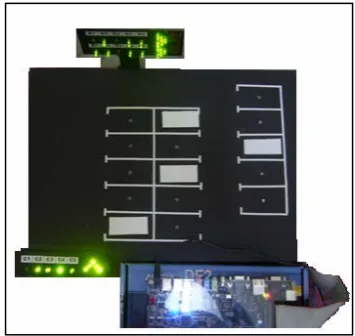
[image:2.595.337.515.522.690.2]The Parking Guidance System Using VHDL contains 3 majoring parts which are; VHDL coding, Display components, and censoring component. Figure 3 shows the prototype of Parking Guidance System
Figure 3 – The prototype of the Parking Guidance System
VHDL coding
the progress of coding, it contains three parts of coding,
which are counter, display, and clock.
In the clock coding, the internal clock which is provided in DE II is being used. It was being converted into 1 Hz clock, which is more convenience for the system.
In counter coding, there were four inputs being used as the main part to control the code running properly. The first input is the total value of the vacancy of the vehicle parking lot which can be set up in 4bits binary code (maximum value = 15). The others two inputs which is count for entrance and the exit. The number of vacant spaces will be subtracted once the “enter” button is being pressed. The value will be added by “1” when the exit button is being press.
A simple D flip-flop model coding was used to memorize the previous and new loaded value. Once the reset button being press, it wills automatic reset the value to the actual value which is set by the 4bits input [2]. All of the calculation value for subtraction and addition will be in temporary signal mode before it was change to the output in the end of the process. IF ELSE statement is being used in this part, at the begin of code, it will be used to detect the reset button whether it is ON or OFF, if it is ON then the input will set to input value. If the reset input is ‘0’ bit, the next step will coming on. In this part, the 1 Hz clock was used for memory purpose [3]. A temporary signal was used to memorize the adder value or the subtraction value and hold the value as long as there were no any bit was sent for the next process.
For the display coding, it contains two types of display codes. For the seven segment display code, it will be used to display the total value of vacancy parking lots. The temporary signal will be used from 4 bits and change to 7 bits using the CASE statement. The 4 bits were changed to 7 bits due to the segment display does have 7 segments and each segment is display by a bit. Every value will be set for display purpose when the input value is ‘0’ the seven segment will come out with “FULL”. It means to announce that there are no more any vacant spaces for parked. The display code is use the coding which will display the location of vacant space once it had been detected.
In the censoring component, the coding is used to interfacing the system with the external circuit. The input bit will be sent by the external sensor circuit. The coding is used to transfer the input to the output which will send to the display component. The value bit of the input is depends on the total parking lot for the system. When bit ‘1’ input was sent, the coding will convert it to ‘0’ and transfer it to the display component as well. The basic coding of VHDL is uses in this part, the output value is the resultant from the input values after passing through the NOT gate.
Display component
There are two part of the component for display purpose. One of the display components is seven segment displays which is already mold on the DE II board. LED display is another one of the display component which is used in this system. Figure 4 shows that the LED display was connected
[image:3.595.345.512.155.280.2]to the 40pins port in the DE II board, the power supply will be supplied by the board and all the data will send by the board as well. This display was located on the place which able to guide the driver drives to the vacant space. The seven segment display on the DE II board is placed at the outside of the parking area for showing the latest vacant space to the public.
Figure 4 - LED display
Censoring component
In this part, the external electronic circuit will be used to sending data bit as an input to the DE II board. The Light Dependent Resistor is used as the sensor of the circuit. It is used to detect the brightness or the darkness situation of the parking lot. When there is a vacant space for vehicle, the LDR will sense the brightness of light and ‘0’ bit will be send to the DE II board. Once there is a vehicle parked in the vacant space, the bottom part of the vehicle will cover on the LDR and make it sense the darkness. It makes a bit ‘1’ is sending to the DE II board and the current situation in the parking lot will be displayed.
IV. RESULT AND ANALYSIS
The results and analysis will be explained on VHDL coding, display components and censoring components.
VHDL coding
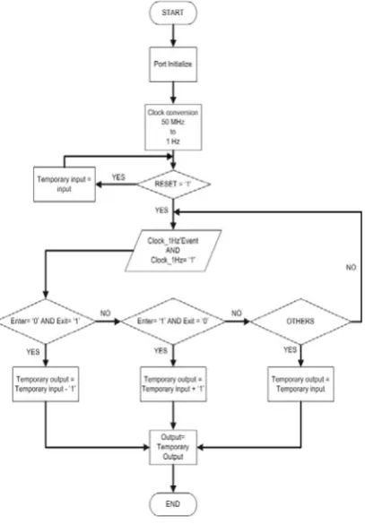
The VHDL coding was divided into three parts, which are counter coding, display coding and the sensor coding. All of these coding were done separately but were combined together in this Parking Guidance System used. The flow chart in Figure 5 shows the flow and the process of the coding system.
time cycle. Its make the counter unable to count accurately.
As an alternative, the code had been downloading into the DE II board and it was success to be functional by showing the output with the blinking LED for every second.
[image:4.595.326.528.61.179.2]For the coding for the seven segment display, there are 28bits which each bit is represent one of the segments for the seven segment display. The seven segment display in the DE II board is active low type, this make all of the bits in the coding must change to low bit to activate the seven segment display. In the coding of this section, the bits from counter were changed to 28bits and all were toggle in the same time. When there is “0000” from the counter, the seven segment display will come out with “FULL”, and for others the seven segment display will show out the actual numbers.
Figure 5 - The flow chart of Parking Guidance System Using VHDL coding
Display component
There are three type of display being used in this project. The seven segment display and LCD are used from the DE II board, and third one is the LED display.
(i) Seven segment display and liquid crystal display (LCD)
[image:4.595.69.273.254.547.2]The seven segment display and LCD display were already provided in the DE II board, all function of these two displays were being set by using VHDL coding. The LCD display is 16x2 displays and it was set by using VHDL coding. Figure 6 shows the LCD display was ON and the sentences “PARKING GUIDANCE SYSTEM” was shown together with the number of vacant spaces by seven segment display.
Figure 6 - The LCD and seven segment display on DE II board
(ii) LED display
Another display was used in this system is LED display. This display is a self constructed circuit by using LEDs. This circuit was connected to the GPIO 40 pins ports in the DEII board. The board will supply +3.3V to the circuit and light up all the LED by the setting of coding in DE II board. All of the display in this project is fully controlled by the coding as well. The data from the sensor circuit will send to the main processor and after that it will be send to the LED which will switch ON the LED if there is a vacant space.
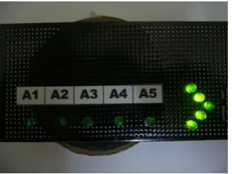
In Figure 7, the display shows the location of the vacant spaces. The ON led represent there is a vacant space for the vehicle and OFF mode LED represent the space was already in park.
Figure 7 - The LED display in Parking Guidance System
Sensor component
The sensor component circuit content of the LM324 op-amp IC. This IC was used for the comparator circuit that will compare the current condition of the parking lot. When there was a car parked in the parking lot, the sensor will sense it and ON the circuit with the output of +2.5V. This output voltage will send to DE II board and it will OFF the location LED in the LED display to show that the vacant space was parked.
The circuit was connected to the non-inverting input and the input signal going below the reference level could cause the output ON below than the Vref [5]. When the light fall
[image:4.595.307.521.427.564.2]above half of the supply voltage, the output of the
[image:5.595.66.256.98.222.2]comparator will turn ON and start send bit ‘1’ to the DE II board.
Figure 8 - The location of photo resistor in the parking lots
The location of photo resistor in the parking lots is depicted in Figure 8. The photo resistor is measured under the normal light condition and it has a resistance about 38KΩ and when it near to the dark it will increase until about 84KΩ. In order to decrease the sensitivity of the sensor, the value of the resistor on the LDR need to be increase and it had been set to 100KΩ. By placing 100KΩ
resistor, the sensitivity of the photo resistor will be decreased and it will affect the result when there is not strong light or any shadow fall on to the photo resistor. When the a vehicle is moving into the parking lot, the bottom of the vehicle will block the light and make the circuit operate when it is in dark condition. The ‘1’ bit will be send to the processor by using the 40 pins expansion ports, and it were set by using Quartus II software.
V. CONCLUSION
As the conclusion, the designed project was able to detect the vacant spaces in the parking garage. Besides that, this project also able to display the total number of vacant spaces and the actual location of the vacant spaces. The whole parking system was designed by using Altera Quartus II and it was applied to the Altera DE II board which was function as the main board for the entire system. By using DE II board as the main processor of this system, it shown that the DE II board is not only is designed for education purpose, but it also can be created as a main processor which able to replace the computer board and it will reduce the using of electronic component by wrote the coding and apply into the board.
REFERENCES
[1] Altera Corperation, Introduction to Quartus II manual, Altera Corporations, 2004.
[2] Weng Fook Lee, VHDL Coding and Logic Synthesis with Synopsys”, Academic Press, 2000.
[3] J.O. Hamblen,T. S. Hall and M. D. Furmanm, Rapid Prototyping of Digital Systems-Quartus II Edition, Springer Science Business Media Inc., 2006.
[4] Volnei A. Pedroni, Digital Electronic and Design with VHDL, Morgan Kaufmann Publisher, 2008.
[5] Robert L. Boylestad and Louis Nashelsky, Electronic Devices and Circuit Theory, Pearson Education. Inc., 2006.
[6] Seong-eun Yoo, Poh Kit Chong, Taehong Kim, Jonggu Kang, Daeyoung Kim, PGS: Parking Guidance System based on Wireless Sensor Network, Information and Communications University Daejeon, 2008.
[7] Siemens Industrial Solutions and Services (I&S), SIPARK Intelligent Traffic Systems, Siemens Industrial Solutions and Services (I&S), 2006.