Active Robot Hand Compliance using Operational Space and Integral
Sliding Mode Control
Jamaludin Jalani
1, Nasiruddin Mahyuddin
2, Guido Herrmann
2and Chris Melhuish
3Abstract— This paper establishes a novel approach of robust active compliance control for a robot hand via an Integral Sliding Mode Controller (ISMC). The ISMC allows us to intro-duce a model reference approach where a virtual mass-spring damper system can be used to design a compliant control. In order to allow for practical grasping, we consider the shape of the object to be grasped. Hence, the work exploits a grasping technique via Cylindrical and Spherical coordinate systems due to their simplicity and geometric suitability. The control uses the operational space approach. Thus, the control is split into a task control and a particular optimizing posture control. The experimental results show that target trajectories can be easily followed by the task control despite the presence of friction and stiction while the posture controller maintains a desired finger posture. When the object is grasped, the compliant control will automatically adjust to a specific compliance level. Once a specific compliance model has been achieved, the fixed compliance controller can be tested for a specific scenario. The experimental results prove that the BERUL hand can automatically and successfully attain different compliancy levels for a particular object via the ISMC.
I. INTRODUCTION
Emulating the human hand via a robot hand to perform a grasping task can be challenging [1], [2], [3], [4],[5]. One of the functions required by a robot hand is the ability to grasp any objects without damage. For this, a compliant control strategy is important to provide such grasping technique. Some effort has been devoted to realize compliant control [6], [7], [8], [9] based on passive mechanical compliance which is not easily tunable once practically implemented. Different active compliant control strategies have been pro-posed by [10], [11], [12], [13], [14]. For instance, PD control [15] is one option, although instability may occur (in particular when the hand is in contact with other objects); this might be due to the lack of an accurate model for the robot hand. Hybrid compliance [16], [17] has resolved some of the issues [18, Chapter 9, e.g. pp 397]. The control approach introduces two states [19], [16]. The first state is controlling the positioning error which is also known as controlling an unconstrained mode while the second state is providing force control in a particular direction. Between these two states, there is a transition mode from positioning control to force control. Early controllers resolved this through a switching mode [16] which may be discontinuously achieved. Switch-ing actions may be uncertain and cause instability [20]. More recent solutions have resolved this in a geometric approach, where the directionality expressed by the kinematics Jaco-bian defines the directions for position and force control [20], [18], [17]. Directional force control approaches are ideal in industrial applications [16], but may be generally problematic in scenarios with humanoid robot hands, where the environment is uncertain and multidirectional (despite
1
J. Jalani is now with the Department of Electrical Engineering Tech-nology, Universiti Tun Hussein Onn Malaysia, 86400, Batu Pahat, Johor, Malaysia. He conducted this research work at the Faculty of Engineering, Department of Mechanical Engineering, Univ. of Bristol, BS8 1TR, UK
2
MN. Mahyuddin and G. Herrmann are with Faculty of Engineering, Department of Mechanical Engineering, University of Bristol, BS8 1TR, UK,[email protected]
3
C. Melhuish is with the Bristol Robotics Laboratory, University of the West of England, Bristol, BS34 8QZ, UK
exceptions for directional compliance [17]). Thus, robustness to model and environmental uncertainty for compliance control is essential.
In this paper, an integral sliding model control (ISMC) using a model reference idea will be discussed. The reference model will introduce a virtual mass-spring and damper system which will determine the compliant control character-istics, i.e. the ISMC approach is not switching between two different states. ISMC (see [21], [22] for tracking) is a control approach which can counteract system uncertainties and is particularly useful for mechanical systems with stiction and friction. Apart from safely grasping an object through compliance strategies, it is desirable that the robot hand is able to adapt to different compliant levels. This can be realized through the automatic alteration of the above mentioned reference model in an initial automatic tuning process of the model parameters.
Providing sufficient knowledge of the object geometry is also an important criterion in order to plan motions and com-pute successful grasps. Interesting results from [23] can assist researchers to plan their grasping technique. The results show that over 50% of the required grasps are cylindrical, and it is possible for a three-fingered hand to achieve over
90% of these grasps using a cylindrical design approach (see also [24]). Thus, for a suitable grasping geometry, a tested cylindrical coordinate system can be very helpful. In addition, we also suggest a spherical coordinate system
for objects grasped by the thumb finger. This allows for radial thumb abduction. When touching an object, a human hand does not require very high accuracy. The grasping task needs to guarantee that the fingers sufficiently surround the object, staying in good contact and creating a suitable ergonomics-inspired posture [25]. Thus, the hand grasping may be split into a task where the finger tips touch/grasp the object, while the fingers overall remain in good contact with the object through a suitable finger posture. Hence, a simple way to achieve this desired grasping is by using the operational space approach [26]. In general, the underlying concept is based on the decomposition of the control signal into a task controller and a posture controller. This may have some similarity to the hybrid force/velocity approach of [18, pp.396]. However, the operational space control approach lends itself to a control approach where a high accuracy finger joint trajectory can be avoided. Thus, the main contributions of this paper are
• Introduction of a compliance reference model subject
to an external measurement signal to be used via an Integral Sliding Mode Control (this avoids scheduling methods and hybrid compliant control approaches).
• Control of a robot hand via the operational space
approach using spherical and cylindrical coordinates.
• Robust finger (i.e. hand) posture optimization via a
robust sliding mode posture controller (e.g. [27]) which allows for a practical grasping trajectory and reduces the need for high accuracy.
• Approach for compliant control which is non switching. • Suggestion of an automatic tuning procedure for the
compliance reference model.
II. ELUMOTIONHAND
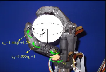
Fig. 1 shows the Bristol Elumotion Robot Hand (BERUL). It is to note that all fingers, i.e. index, middle, ring and small finger consist of three links and three joints except the thumb finger. The thumb has four joints and four links. For the majority of the fingers, these joints are connected through a single, flexible pushrod which is then actuated by a leadscrew mechanism that converts a linear movement into a rotary movement for an electrical motor. Nine servo motors have been attached to various fingers of the BERUL hand. In particular, one motor actuator is used for the small and ring finger and two actuators used for the middle, index and thumb finger. Although the middle and index fingers are hav-ing two actuators, they follow a planar motion. In contrast, the thumb end effector motion is more complex due to the two applied actuators and their mechanisms: One actuator is used for the push-rod mechanism (i.e. for palmar abduction), while the other motor introduces rotational motion similar to radial abduction. The push rod and leadscrew actuation will create a relational movement of the intermediate and distal phalange links in direct connection to the first (proximal phalange) link of each finger. Measurement of the kinematics of each finger showed that the relationship of the joint movement is sufficiently linear, so that the effect of the pushrod constraining the fingers can be modelled similar to a pulley belt system [28]. This allows a reasonably accurate computation ofthe end positions of a each finger tip
via forward kinematics in the targeted spherical/cylindrical coordinate system using the motor position, i.e. the first directly actuated joint angle values of each finger. For this paper, we focus on the ring, index and thumb finger, as examples of fingers with one and two actuators with planar and non-planar motion.
III. CYLINDRICAL AND SPHERICAL COORDINATES
In order to allow for practical grasping for the BERUL fin-gers, we exploit the cylindrical and the spherical coordinate system. The cylindrical or the spherical coordinate system can be centered at the object to be grasped (see Figure 4 in [29] and Figure 1 for the coordinate system placement. Note that the transformation between Cartesian and Cylin-drical/Spherical coordinates follows a standard mathemati-cal mathemati-calculation.). The cylindrimathemati-cal coordinate system is most suited to the index, middle, ring and small fingers, since these fingers often follow a planar movement, even when they are having several actuators. A thumb generally is more versatile in its movements, as it has to move from its initial position around objects (palmar and radial abduction). Thus spherical coordinates are suited for the thumb. For grasping, it is not
Fig. 1. Spherical coordinate system used for thumb finger of BERUL hand
necessary to control the joint position of each finger at a high accuracy. Grasping can be easily directed by the radial position r of the finger tip and a preferred posture in case fingers are multi-redundant. Hence, both the cylindrical and spherical coordinates lend themselves to finger control via the radiusr.
IV. CONTROLLER STRUCTURE
[image:2.595.314.554.267.435.2]The overall structure for active compliance controller for the BERUL fingers is depicted in Figure 2. It has two primary parts: the first part is the ISMC based compliance controller for the task. The second is the posture controller. This is possible as we employ the operational space approach, which allows the geometric splitting into task and posture control.
Fig. 2. Block Diagram of the ISMC to achieve active compliance control for the BERUL fingers
A general model of a robot is
M(q)¨q+V(q,q˙) ˙q+G(q) +Df =τ. (1) where M, V and G provide mass, velocity and gravity terms respectively. The vectorDf represents amplitude lim-ited friction and stiction disturbances and uncertainties; in addition, Df can also represent forces which result from interaction of the hand with other objects.1The torque vector
τ represents the external actuating torques affecting each joint. This representation certainly holds for each specific finger for which we develop here the controller. It is to point out that in the context of the robot hand, the termV(q,q˙) ˙q
has very little significance. However, the terms G(q) and
Df clearly have significant influence, considering that the practical BERUL hand is to be attached and moved with the robot arm. Moreover, friction and stiction has significant effect due to the pushrod mechanism.
A. TASKCONTROL: Model-reference ISMC for compliance and robustness
As discussed before, the task coordinate of interest is the radial positionr (in the cylindrical/spherical coordinate system), which can be determined by the joint coordinates
q. The relevant Jacobian, J(q), of the task coordinate r is defined as
J =∂r
∂q (2)
1For control, the forcesD
f do not need to be known, as sliding mode
[image:2.595.85.266.655.779.2]Considering kinematic redundancy of thumb and ring fingers (i.e. the dimension of the task is strictly less than the dimension of the configuration space), the following pseudo inverse as in [30], [31] is used:
¯
J =M−1
JT(J M−1 JT)−1
(3) Thus, using equation (2) allows us to project joint space dynamics (1) into the task space dynamics of the radiusras follows:
¯
M(q)¨r+ ¯V(q,q˙) ˙r+ ¯G(q) + ¯Df=F. (4) where M¯(q) = (J M−1
JT)−1
, V¯ = ¯JTV −MJ˙q˙, G¯ =
¯
JTG and F = ¯JTJ. For control, estimates of all system
parameters are needed, i.e.Mˆ¯ is the estimate forM¯ whileVˆ¯,
ˆ ¯
Gare the two other respective estimates. Friction and other un-modeled forces are Df¯ = ¯JTDf. A typical feedback
linearization controller [18, pp.330] with PD controller is:
F0= ˆM¯(q)f∗+ ˆV¯(q,q˙) ˙r+ ˆG¯(q). (5)
where f∗ = ¨rd(t) +Kpre+Kdre˙ andre is a radial error
defined asre(t) =rd(t)−r(t)with[rd(t) ˙rd(t) ¨rd(t)]being the reference trajectory and its time derivatives. Multiplying
J in equation (5), the task space control is obtained as follows.
τtask=JT(F0+F1) (6)
where F1 is to be defined next: Note that the expression
(5) contains an estimate of the finger dynamics. These estimates are generically not easily obtained so that the estimation error with respect to( ¯M¨rd+ ¯V(q,q˙) ˙r+ ¯G(q)−
ˆ¯
Mrd¨ −Vˆ¯(q,q˙) ˙r−Gˆ¯(q))and also the additional forcesDf¯
need to be compensated for. Although these errors can be significant, they are in general amplitude bounded. Thus, the task controller, F0 (6), is now to be augmented by an
integral sliding mode controller,F1, to allow for the required
controller robustness and active compliance.
1) Integral Sliding Mode Controller: Now, by using the ISMC approach [21], the task control torque is extended by the nonlinear sliding mode termF1 (6):
F1=−Γ0( s
ksk+δ), δ >0, Γ0>0. (7)
and
s= ˙re+Ksre+Ki
Z t
0 redξ−
Z t
0
GfHdξ−re˙ (0)−Ksre(0)
(8) where re(0) and re˙ (0) are initial conditions. Consider that Rt
0(·)dξ are integrals over time with integrant ξ. Following
the analysis of [21], the sliding mode term enforcess = 0
for δ→0+and large enoughΓ0>0, i.e.
Γ0>
( ¯M−Mˆ¯)¨rd+ ¯V(q,q˙) ˙r+ ¯G(q)−
ˆ ¯
V(q,q˙) ˙r−Gˆ¯(q)+ ¯Df
(9) (The scalar δ > 0 is introduced to avoid any possible chattering in the control action due to the nonlinear sliding mode term.) This implies that the following second order dynamics govern fors= 0the robot finger:
¨
re+Ksre˙ +Kire=GfH (10) where Gf is a positive scalar and H is an external force measurement, obtained via specially introduced sensors.2Ks is a damping coefficient and Ki is a stiffness coefficient of the reference model. In contrast to former work, the
2In the case of the BERUL hand, we have used Single-Point Tactile
Sensors which allow for force sensing at the BERUL finger tips; see Section VII for further detail.
introduction of the external signal into the reference model (10), in particular also for the operational space control context, creates a robust ISMC based compliance control approach.
2) Robustness: The ISMC has been a well investigated control method due to its robustness [32], [33], [34]. Thus, further significant technical detail which proves robustness, in particular (8), is here avoided. It has been shown that ISMC is superior in the context oftrajectory followingfor the BERUL hand subjected to friction, in comparison to many other control methods [22], [28].
B. POSTURECONTROLFORGRASPING
The posture controllers are meant to regulate the remaining degree of freedom, which is not controlled by the task controller. The index and the thumb fingers have both two actuators to control their finger tip position in terms of radial position and posture. The idea for the posture is to minimize a cost function,U(q), which guarantees a certain ‘optimal’ (nominal) positioning of the redundant degrees of freedom. In case of [26] and [27], this was an effort minimizing cost function based on the effects of gravity. This has induced human like motion for a robot torso and arm control. In our case, the effects of gravity are too strongly varying with the hand movement so that a more specific hand posture cost is needed here.
1) Posture Control for Index and Thumb Fingers: We consider the thumb and the index finger which have two actuated degrees of freedom, q1 and q2. The geometric
projection matrix N = (I −JTJ¯T)
is important for the posture task, as it defines the null space of the task controller. (Note that the ring finger discussed here in this paper has only one actuator where all joints are connected through a push rod. For this fingerN = 0). The overall control signal for a BERUL finger can be written as:
τ =JT(F0+F1) +NT(−Kdpq˙−KSL
ˆ¯
Mˆs
ksˆk+δSL) (11)
where Kdp >0,KSL>0 andδ >0. The variable ˆs
ˆ
s=B( ˙q+Kv(∂U
∂q)
T)
(12)
introduces a sliding mode variable for the posture control where
B= (I−JT(J JT)−1
J) (13)
The matrix B is a projection matrix similar to N. In the ideal case, the nonlinear sliding mode term enforces ˆs= 0
for δSL → 0+; the posture is therefore robust to system uncertainty [27]. This introduces a gradient descent approach which minmimizesU(q)(additional explanations in [27]).
Instead of using gravity terms to derive the posture con-troller function [26], [27], a new cost function is given as follows:
U(q) =w1(q1−φ1) 2
+w2(q2−φ2) 2
(14)
w1 >0, w2 >0, φ1 andφ2 are the choice of the designer
for the degrees of freedom toq1 andq2 respectively.
Remark 1: The cost function U(q) is to be minimized to guarantee a nominal posture of the thumb and the index finger. Thus, once U(q) = 0, the nominal position would be q1 =φ1 and q2 =φ2. However, the task controller has
V. COMPLIANCE CONTROL AND MODEL REFERENCE BEHAVIOR
A. Compliance
For compliance, we reconsider the sliding variables and its derivative:
˙
s= ¨re+Ksre˙ +Kire−GfH (15) When sliding motion is achieved, thens= 0and in particular
˙
s = 0. For s˙ = 0, the error dynamics are defined by the damping constant Ks, the spring constant Ki and the external force measurement signalHintroduced via the input distribution gainGf, namely
¨
re+Ksre˙ +Kire=GfH (16) This defines a reference model allowing for active com-pliance control. This contrasts to the recent use of ISMC, where the sliding mode dynamics generally define a nominal closed loop behavior without external signals. This is an important tool as the controller guarantees a well defined level of compliance despite the high degree of uncertainty and friction in the robot hands.A virtual demand model for this is
¨
rr=−Ksrr˙ −Kirr+GfH+Ksrd˙ +Kird+ ¨rd. (17) Thus, the joint coordinates r have to follow the virtual demand rr in the ideal case, given an original demand rd.
B. A Virtual Mass-Spring Damper Reference
It is noted that from (16) follows
re(s)
H(s) =
Gf
s2+Kss+Ki (18)
where Ks = 2ζωn and Ki = ωn2
. The scalars ζ and ωn
are damping ratio and natural frequency respectively. Thus, different Ks, Ki and Gf to be used in order to obtain compliance levels.
C. Computation of Compliance Level for an Object
The reference model cannot be arbitrarily determined and it needs to be bespoke, suitably adjusted to the context of the object handled by the robot fingers, in particular when considering the steady state force equilibrium. For this, let us consider the following mass-spring damper system:
¨
re+Kss
mvre˙ + Kii mvre=
1
mvf (19)
where mv is a virtual mass of the spring, Kss is a virtual damping constant and Kii is a virtual spring constant. By equating equation (19) with equation (16) the following relations are obtained.
Kss
mv = 2ζωn=Ks; Kii mv =ωn
2
=Ki; GfH = 1
mvf
(20) where Gf = 1
mv, H = f, ωn. The target is now to
determineKss, Kii andmv via suitable practical tests and design requirements for compliance and transient behavior. We may assume that ζ and ωn are given to establish a suitable transient behavior, which fixes Kss and Kii. The sensitivity to the measured force is adjusted through the input gainGf= 1
mv.
It is now the aim to findGf in a semi-automated process. This is to be carried out once, before any serious compliant interaction task, which is to ensure safe interaction after this initial tuning process. The software-implemented process is given as follows.
1) Gf is set to a significantly large initial value which will make the reference model highly sensitive to any external signal H. A task controller is initiated for a constant demand rd.
2) The finger is controlled via rd so that it touches the object. For the finger to reach rd, it would have to penetrate the touched object. This is certainly to be avoided by the compliance controller and an adjusted value rr (17). The initial large Gf > 0 makes the reference model highly sensitive to a touching interac-tion of the object with the finger. Once the finger has contacted the object, a sensor signal H is measured. Since a constant target value for rd is set, the sensor signalH is steadily increasing.
3) A levelHL1 is used toinitiate the tuning process for Gf. Hence, once the sensor signal H is larger than
HL1 for a sufficiently long time, the value of Gf is
very slowly decreased in an automated fashion. This will make the reference model less sensitive toH and forcerr to be closer tord (17).
4) Once the force sensor signal,H, has surpassed a level
HL2, (HL2 ≥ HL1) the decreasing value of Gf is
kept fixed. Hence, the choiceHL2defines the maximum force applied to the object and therefore determines the compliance level of the reference model via the fixed parameters Ks, Ki and Gf. These values are now available for further use.
In summary, the process above allows to introduce a compliancy reference model for a specific object-finger force interaction levelHL2in a semi-automated manner. This is to be carried out once for the reference model to be used later for the specific class of object in robot-object interaction.
VI. EXPERIMENTALSETUP
As a real-time interface, the dSPACE DS1006 Controller Board is used to interact with the BERUL fingers. MAT-LAB/Simulink models can be compiled easily to real-time code which makes it possible to implement new ideas rapidly. The advantages of using dSPACE are that it is easy-to-use real-time hardware, providing simple and practical graphical programming. The I/O interfaces are conveniently connected via Real-Time Interface blocks for seamless integration into MATLAB/Simulink.
VII. RESULTS
The results are divided into three different cases. Case 1 investigates the effectiveness of the posture controller. Case 2 is for tracking performance. Case 3 shows the performance for different compliance levels for a specific object.
A. Posture Controller Parameters and Results - Case 1
The gains used for the posture controller in particular for the index finger areKdp = 2, KSL = 16,Kv = 4,w1= 3
andw2= 3. The nominal link positionsφ1andφ2are chosen
as φ1 = 0.45rad and φ2 = 1.5rad. This in fact defines a
finger in a slightly bent, almost-open hand position. Thus, once the task controller is enabled (task control has priority over posture), the nominal ”almost-open” finger posture (following ergonomics studies in [25]) will guarantee that the finger encloses the object. On the other hand, the gains for the thumb finger are Kdp = 2, KSL = 160, Kv = 4,
w1 = 2 and w2 = 2. The nominal positions of the thumb
are φ1 =−2.5rad andφ2 = 1.5rad. They enforce for the
thumb finger to move from an initial (open hand) position to a position (Figure 3, subfigure 1) where the thumb is in front of the object (Figure 3, subfigure 6). Hence, although the task controller has priority to achieve the correctradial finger tip position, the posture controller guarantees that the redundant degrees of freedom of the hand permit practical, ergonomics-based grasping positions [25], which is not achievable via task control only.
B. Reference Model Parameters
Using (16), the reference model parameters have been chosen as follows: Ks = 8 and Ki = 18 which implies
ωn = 4 and ζ = 0.9. The choice of ωn = 4 and ζ = 0.9
will guarantee an approximate settling time for1 second for a critically damped reference model.
C. Tracking Results - Case 2
The results show that, while maintaining a desired posture motion as depicted in Figure 3, the tracking of r can be achieved (see Figure 4). Moreover, the results also show that the fingers satisfactorily follow a desired trajectory (i.e. r
follows rd) during opening and the grasping period. More specifically, the task controller performance is still very good despite the posture controller forces the index finger to retain an ”open” finger position as much as possible. The thumb finger moves to the last position as nominally desired (see Figure 3, subfigures 1-6). Thus, the posture controller guarantees that the fingers do not collide with the touched object. The space operational approach creates a seemingly natural appearance.
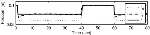
D. Compliance level results for an object - Case 3
We have investigated two different options for the permis-sible contact forces HL2 for grasping a hard rubber ball.
The level HL2 = 0.01 V(0.0433 N) and later HL2 =
0.04V(0.1733N). These force levels are chosen to enable object grasping without damaging the object (and also the robot hand). The lower force HL2 = 0.01 V(0.0433 N)
permits a very light grasp, just avoiding object slippage. The results reveal that a suitable reference model for both
HL2can be satisfactorily achieved for both levels as shown
in Figure 5 and Figure 6 within the first 10 seconds. It shows that different levels of compliance are feasible for the same object. Moreover, the suggested technique to capture an appropriate Gf is reliable since it can be repeated.
Moreover, in Figure 5 and Figure 6, the compliance control action for fixedGf =const.,Gf >0, is assessed. This can be seen after a period of 60 seconds. Note that during the period from 40 seconds to 60 seconds the fingers are open (i.e. not grasping).
It is also visible, in particular for the ring finger that the pressures exerted on the object must be higher for HL2 =
1 2
4 3
[image:5.595.322.546.103.329.2]6 5
Fig. 3. Cylindrical orientation for index and ring fingers while spherical motion for thumb finger
0 20 40 60 80 100 120 0
0.04 0.08 0.12 0.16
Time (sec)
Position (m)
rd r
[image:5.595.311.550.367.417.2](b) Index Finger
Fig. 4. rd-tracking for thumb finger in Spherical coordinates
0.04 V(0.1733 N)in contrast to HL2= 0.01V(0.0433 N)
since rd and rr are slightly closer together. Generally, the gain Gf is smaller for HL2 = 0.01 V(0.0433 N) in
relation to HL2 = 0.04 V(0.1733 N) (see Tables I and
II). Note the rather nonlinear relationship betweenHL2and Gf for the two options. The decrease of Gf from HL2 =
0.01 V(0.0433 N) to HL2 = 0.04 V(0.1733 N) appears
to be small, but is was found to be a repeatable result. The small difference in Gf for HL2 = 0.04V(0.1733 N) and HL2= 0.01V(0.0433N)may be explained by the material
properties of the touched object.
TABLE I
DESIREDFORCE FOR LEVEL0.0433 N (0.01V)-HARD RUBBER BALL
F inger Gf HL2 (V)
Thumb 9.519 0.01 Index 9.959 0.01 Ring 9.993 0.01
0 10 20 30 40 50 60 70 80 0.05
0.1
Time (sec)
Position (m)
[image:5.595.312.552.584.698.2]rd rr r
Fig. 5. Compliance performance for level 0.0433 N (0.01V)
TABLE II
DESIREDFORCE FOR LEVEL0.1733N (0.04V) -HARD RUBBER BALL F inger Gf HL2 (V)
0 10 20 30 40 50 60 70 80 0.05
0.1
Time (sec)
Position (m)
rd r
r
[image:6.595.51.292.103.160.2]r
Fig. 6. Compliance performance for level 0.1733 N (0.04V)
VIII. CONCLUSION
In this paper, we propose a novel approach for active com-pliance control via Integral Sliding Mode Control (ISMC). The ISMC allows us to introduce a model reference approach where a virtual mass-spring damper can be used to design a compliant control. The finger motion is controlled by a posture controller and a task controller as parts of an operational space controller. Both controllers use sliding mode methods to ensure robustness. Results show that the task controller can achieve indeed good tracking performance despite high levels of stiction and friction. The idea of using cylindrical and spherical coordinates and the posture controller of the index and thumb finger guarantees that both fingers move around the touched object without collision and it gives priority to the grasping task. This will allow for practical grasping via the chosen geometry.
The tactile pressure sensors are mounted on the BERUL fingers to permit only a desired force level to affect any object. The effectiveness of the compliant control when grasping similar object has been successfully demonstrated at different desired force levels via an automated tuning proce-dure. The automated tuning process has shown that reference models for particular force levels can be easily achieved. It shows that higher desired forces require a ‘stiffer’ reference model. The method is also suitable for achieving compliance levels for different objects, as demonstrated in additional studies (These studies are not included in this paper due to space reasons).
ACKNOWLEDGMENT
The CHRIS (Cooperative Human Robot Interaction Sys-tems) project is funded by the European Commission’s Seventh Framework Programme (FP7) and will run from 2008-2012. This research is also partially funded by the Malaysian Government.
REFERENCES
[1] S. Jacobsen, J. Wood, D. Knutti, and K. Biggers, “The utah/m.i.t. dextrous hand: Work in progress,” vol. 3, no. 4, pp. 21–50, 1984. [2] ShadowRobot, “Design of a dextrous hand for advanced clawar
applications,” inIn Proceedings of CLAWAR, 2003, pp. 691–698. [3] M. Grebenstein, A. Albu-Schaffer, T. Bahls, M. Chalon, O. Eiberger,
W. Friedl, R. Gruber, S. Haddadin, U. Hagn, R. Haslinger, H. Hoppner, S. Jorg, M. Nickl, A. Nothhelfer, F. Petit, J. Reill, N. Seitz, T. Wim-bock, S. Wolf, T. Wusthoff, and G. Hirzinger, “The dlr hand arm system,” inRobotics and Automation (ICRA), 2011 IEEE International Conference on, may 2011, pp. 3175 –3182.
[4] C. Borst, M. Fischer, S. Haidacher, H. Liu, and G. Hirzinger, “Dlr hand ii: experiments and experience with an anthropomorphic hand,” in Robotics and Automation, 2003. Proceedings. ICRA ’03. IEEE International Conference on, vol. 1, Sept. 2003, pp. 702–707. [5] J. Vandeweghe, M.Rogers, M.Weissert, and Y. Matsuoka, “The act
hand: Design of the skeletal structure,” inProceedings of the 2004 IEEE International Conference on Robotics and Automation (ICRA ’04), May 2004.
[6] M. R. Cutkosky,Robotic Grasping and Fine Manipulation. Norwell, MA, USA: Kluwer Academic Publishers, 1985.
[7] K. L. Johnson, Contact Mechanics. Cambridge, UK: Cambridge University Press, Cambridge, 1985.
[8] K. Shimoga and A. Goldenberg, “Soft robotic fingertips,”The Inter-national Journal of Robotics Research, vol. 15, no. 4, pp. 320–334, 1996.
[9] L. Biagiotti, C. Melchiorri, P. Tiezzi, and G. Vassura, “Modelling and identification of soft pads for robotic hands,” in IEEE/RSJ Interna-tional Conference on Intelligent Robots and Systems (IROS), 2005. [10] H. Liu and G. Hirzinger, “Cartesian impedance control for the dlr
hand,” inIntelligent Robots and Systems, 1999. IROS ’99., 1999. [11] A. Kugi, C. Ott, A. Albu-Schaffer, and G. Hirzinger, “On the
passivity-based impedance control of flexible joint robots,”IEEE Transactions on Robotics,, vol. 24, no. 2, pp. 416 –429, 2008.
[12] A. Albu-Schaffer, C. Ott, and G. Hirzinger, “A unified passivity-based control framework for position, torque and impedance control of flexible joint robots,”The International Journal of Robotics Research, vol. 26, no. 1, pp. 23–39, 2007.
[13] S. Khan, G. Herrmann, A. G., Pipe, and C. Melhuish, “Safe adaptive compliance control of a humanoid robotic arm with anti-windup compensation and posture control,”International Journal of Social Robotics, vol. 2, no. 3, pp. 305–319, 2010.
[14] Z. Chen, N. Lii, T. Wimboeck, S. Fan, M. Jin, C. Borst, and H. Liu, “Experimental study on impedance control for the five-finger dexterous robot hand dlr-hit ii,” inIntelligent Robots and Systems (IROS), 2010 IEEE/RSJ International Conference on, 2010, pp. 5867 –5874. [15] P. Tomei, “Adaptive pd controller for robot manipulators,”Robotics
and Automation, IEEE Transactions on, vol. 7, no. 4, pp. 565 –570, aug 1991.
[16] A. Jaura, M. Osman, and N. Krouglicof, “Hybrid compliance control for intelligent assembly in a robot work cell,”International Journal of Production Research, vol. 36, no. 9, pp. 2573–2583, 1998. [17] K. Mouri, K. Terashima, P. Minyong, H. Kitagawa, and T. Miyoshi,
“Identification and hybrid impedance control of human skin muscle by multi-fingered robot hand,” inIROS 2007. IEEE/RSJ International Conference on Intelligent Robots and Systems, 2007., 2007, pp. 2895 –2900.
[18] B. Siciliano, L. Sciavicco, L. Villani, and G. Oriolo,Robotics: Mod-elling, Planning and Control. Springer, 2008.
[19] Y. Xu and R. Paul, “On position compensation and force control sta-bility of a robot with a compliant wrist,” inRobotics and Automation, 1988. Proceedings., 1988 IEEE International Conference on, vol. 2, April 1988, pp. 1173 –1178 vol.2.
[20] B.-H. Kim, S.-R. Oh, I. Suh, and g.-J. Yi, “A compliance control strategy for robot manipulators under unknown environment,”KSME International Journal, vol. 14, pp. 1081–1088, 2000.
[21] J. Shi, H. Liu, and N. Bajcinca, “Robust control of robotic manipula-tors based on integral sliding mode,”International Journal of Control, vol. 81, pp. 1537–1548 vol.81, 2008.
[22] J. Jalani, G. Herrmann, and C. Melhuish, “Underactuated fingers controlled by robust and adaptive trajectory following methods,” International Journal of Systems Science, 2012.
[23] D. Akin, C. Carignan, and A. Foster, “Development of a four-fingered dexterous robot end effector for space operations,” inIEEE International Conference on Robotics and Automation, 2002. [24] T. Geng, M. Lee, and M. Hlse, “Transferring human grasping synergies
to a robot,”Mechatronics, vol. 21, no. 1, pp. 272 – 284, 2011. [25] S. C. Bae, “Investigation of hand posture during reach and grasp
for ergonomic applications,” Doctor of Philosophy, University of Michigan, 2011.
[26] V. DeSapio, J. Warren, O. Khatib, and S. Delp, “Simulating the task-level control of human motion: a methodology and framework for implementation.”The Visual Computer, pp. 289–302, 2005. [27] A. Spiers, G. Herrmann, and C. Melhuish, “An optimal sliding mode
controller applied to human motion synthesis with robotic implemen-tation,” inAmerican Control Conference (ACC), 30 2010-July 2 2010, pp. 991 –996.
[28] J. Jalani, G. Herrmann, and C. Melhuish, “Robust trajectory following for underactuated robot fingers,” inUKACC International Conference on CONTROL 2010, September 2010, pp. 495–500.
[29] ——, “Robust active compliance control for practical grasping of a cylindrical object via a multifingered robot hand,” inIEEE Interna-tional Conference on Robotics, Automation and Mechatronics (RAM), September 2011.
[30] O. Khatib, “A unified approach for motion and force control of robot manipulators: The operational space formulation,” IEEE Journal of Robotics and Automation, vol. 3, no. 1, pp. 43 –53, february 1987. [31] ——, “Inertial properties in robotic manipulation: An object-level
framework,”The International Journal of Robotics Research, vol. 14, no. 1, pp. 19–36, 1995.
[32] M. Yokoyama, G.-N. Kim, and M. Tsuchiya, “Integral Sliding Mode Control with Anti-windup Compensation and Its Application to a Power Assist System,”Journal of Vibration and Control, vol. 16, no. 4, pp. 503–512, 2010.