On the Effect of Relay Position in Carrier
Interferometry OFDM for Cooperative Diversity by
Wavelet Transform
Cebrail Ciflikli1,*, Bilgin Yazlik2
1Department of Electronics and Automation, Erciyes University, Turkey
2Erciyes University Technology Transfer Office Research and Application Center, Erciyes University, Turkey
Copyright©2019 by authors, all rights reserved. Authors agree that this article remains permanently open access under the terms of the Creative Commons Attribution License 4.0 International License
Abstract
In a wireless communication system, cooperative diversity can be used to combat fading effects. In cooperative diversity, the system uses idle antennas, which are located at different locations, as relays. Cooperative communication with OFDM is widely used in communication systems and it enhances communication performance of the system. There are different methods to enhance the performance of OFDM systems, carrier interferometry code is one of them. While, carrier interferometry code increase the performance of the system and also reduces PAPR level. Carrier interferometry codes can be implemented on an OFDM system by using FFT and wavelet. In this paper we investigate the effect of the relay position on the carrier interferometry cooperative OFDM system which uses wavelet transform. The effect of the relay position is investigated over different combiners and relaying strategies. The results show that, relay position effects the performance of the system and optimal location for the relay is right between source and destination.Keywords
Carrier Interferometry, Ci-OFDM, Cooperative Network, Cooperative Diversity, Relay Position, Wavelet1. Introduction
Because of the nature of the wireless communication system, any transmitted signal is exposed to fading effects [1], [2]. Fading effects can lead to performance loss on communication system. There are various methods to combat channel’s fading effects and diversity is among them. Copies of the original signal are transmitted to the receiver over different paths to realize diversity effect. Copies of a signal can transmit in different slots of time,
frequency and spatial domain. At the end of the transmission, the receiver has several copies of the original signal which arrive over different time, frequency or location slots, then the receiver combines all of the incoming signals by using different combiners to benefit diversity gain [1].
If there is not enough resource to realize the multiple antenna system for spatial diversity, then cooperative diversity arises as the best alternative. In a cooperative network, there is at least one source, one receiver and one relay; the signal is transmitted to the receiver at least over two channels. Cooperative network achieve spatial diversity effect for wireless communication systems [2]. Cooperative network is a promising technology for 5G communication since it enhances system data transfer rates and uses system resources effectively [1].
Orthogonal Frequency Division Multiplexing (OFDM) is a kind of multicarrier modulation method which is commonly used. OFDM system divides available bandwidth into multiple subcarriers [2]. In the recent past, OFDM has received substantial attention. Digital audio and video broadcasting, IEEE 802.11, DSL internet communication, 4G mobile communications employ OFDM.
Carrier interferometry (CI) codes are used to reduce high PAPR level and enhance BER performance of OFDM system [3]. CI codes are orthogonal codes and by using CI codes, OFDM system uses all available subcarriers instead of allocated subcarriers. This approach leads to performance benefits. CI-OFDM performs better than traditional OFDM system. FFT is used instead of CI spreading codes in [3], according to [3], CI-FFT OFDM has same performance comparing to CI-OFDM system.
OFDM system. In the other work [5] it is showed that wavelet based OFDM receivers has better performance.
In this paper, we realize carrier interferometry OFDM system by using of wavelet transform in a one source, one relay and one destination cooperative wireless network and investigate the effect of the relay position on the system performance. Performance investigation of the relay position is realized by using different combining techniques.
2. Cooperative Diversity
Wireless communication systems use different diversity techniques to combat fading effects. Copies of the original signal transmit to the receiver in different time slots for time diversity. At the end of the process, the receiver will have at least two copies of the original signal which arrives in different time slots. For frequency diversity technique, copies of the original signal transmit to receiver in different frequency slots. This type of diversity demands more channel bandwidth.
For spatial diversity, sources which are located in different locations, send the same signal to the receiver. Receiver gets signals which come from different paths. It is possible to use multiple antennas on the same device, but the distance between antennas must be long enough to avoid interference. At this point, device size limitations arise as an important design problem.
Spatial diversity is a space based diversity technique, but there are limitations to use this technique. To overcome the limitations, cooperative diversity is an useful alternative. Cooperative diversity can be considered as a special kind of spatial diversity technique. In a cooperative network there is at least one relay antenna, which means that the original signal transmits to receiver over at least two different paths (source to receiver, relay to receiver), then receiver combines all of the incoming signals to benefit from diversity gain.
3. Relaying Strategies
Relay has a key role in a cooperative network, it gets a signal from the source and then resend it to the receiver. There are two very well-known relaying strategies: Decode and Forward (DAF) and Amplitude and Forward (AAF). At AAF, relaying node receives the original signal with noise, then amplitude the received signal and resend it to the receiver [6], but in this strategy, it is necessary to note that, the noise is also amplified.
At DAF, the relaying node receives the original signal, decodes it, corrects it with the help of error correction codes, re-encodes it and resends it to the receiver [6]. DAF has obviously better performance than AAF [7], [8], but only when there is an error correction code. DAF strategy demands more energy and computational source then AAF
[6]. If energy source limitation is vital for the system, AAF is the best strategy to use.
4. Combining Techniques
In a cooperative network, there are always at least two signal copies which arrive to receiver from different paths. To be able to get diversity gain, it is necessary to combine these incoming signals. There are different combiners, in this paper we use Signal to Noise Ratio Combiner (SNRC), Fixed Ratio Combiner (FRC) and Equal Ratio Combiner (ERC).
ERC is a very simple combining method which is still useful to achieve diversity gain. By using ERC, all of the received signals are combined by adding each other without any weight.
𝑦𝑦𝑑𝑑[𝑛𝑛] =𝑦𝑦𝑠𝑠,𝑑𝑑[𝑛𝑛] +𝑦𝑦𝑟𝑟,𝑑𝑑[𝑛𝑛] (1) Here, 𝑦𝑦𝑑𝑑 is the combined signal with ERC, 𝑦𝑦𝑠𝑠,𝑑𝑑 is the
direct signal and 𝑦𝑦𝑟𝑟,𝑑𝑑 is the relayed signal.
FRC promises better performance than ERC [9], by using this technique, all of the received signals are weighted by a fixed ratio. This fixed ratio must be proportional to the channel quality.
𝑦𝑦𝑑𝑑[𝑛𝑛] =𝑤𝑤𝑠𝑠,𝑑𝑑.𝑦𝑦𝑠𝑠,𝑑𝑑[𝑛𝑛] +𝑤𝑤𝑠𝑠,𝑟𝑟,𝑑𝑑.𝑦𝑦𝑟𝑟,𝑑𝑑[𝑛𝑛] (2) Here, 𝑤𝑤𝑠𝑠,𝑑𝑑 and 𝑤𝑤𝑠𝑠,𝑟𝑟,𝑑𝑑 are the distance based weights of
the direct connection and relay connection, respectively. The weights which are used by a combiner is essential in combining process, SNRC uses weights which are proportional to the received signal’s SNR value. Because of that SNRC has better performance than both ERC and FRC [9].
𝑦𝑦𝑑𝑑[𝑛𝑛] =𝑆𝑆𝑆𝑆𝑆𝑆𝑠𝑠,𝑑𝑑.𝑦𝑦𝑠𝑠,𝑑𝑑[𝑛𝑛] +𝑆𝑆𝑆𝑆𝑆𝑆𝑠𝑠,𝑟𝑟,𝑑𝑑.𝑦𝑦𝑟𝑟,𝑑𝑑[𝑛𝑛] (3) Here, 𝑆𝑆𝑆𝑆𝑆𝑆𝑠𝑠,𝑑𝑑 and 𝑆𝑆𝑆𝑆𝑆𝑆𝑠𝑠,𝑟𝑟,𝑑𝑑 are the SNR based weights
of the direct connection and relay connection, respectively.
5. Carrier Interferometry
Carrier interferometry concept arises from the wave which constitutes by super position of the N carrier. 𝑔𝑔(𝑡𝑡) is the sum of the N carrier which is spread by equal ∆𝑓𝑓 frequency slots.
𝑔𝑔(𝑡𝑡) =∑𝑁𝑁−1𝑒𝑒𝑗𝑗(2𝜋𝜋∆𝑓𝑓𝑓𝑓)
𝑖𝑖=0 (4) In a CI/OFDM system, the transmitted nth symbol is
formulated as:
𝑠𝑠𝑛𝑛(𝑡𝑡) =𝐴𝐴.𝑆𝑆𝑒𝑒 �∑ 𝛼𝛼𝑛𝑛𝑞𝑞𝑒𝑒𝑗𝑗(2𝜋𝜋𝑓𝑓𝑐𝑐𝑓𝑓+2𝜋𝜋𝑓𝑓𝑖𝑖𝑓𝑓+
2𝜋𝜋 𝑁𝑁.𝑛𝑛.𝑖𝑖)
𝑁𝑁−1
𝑖𝑖=0 � (5)
where 𝛼𝛼𝑘𝑘𝑞𝑞 denotes qth symbol in the nth stream, 2𝜋𝜋/𝑆𝑆.𝑛𝑛.𝑖𝑖 is the phase offset used to generate the spreading code of the nth symbol and A is the energy.
orthogonal to the CI signal which has its peak value at 𝜏𝜏 point. This special property gives a chance to send signals without intersymbol interference (ISI). CI codes can be employed in OFDM systems, CI coded OFDM systems show better performance [10], [11], [13] and CI codes have reduce effect on the Peak to Average Power Ratio (PAPR) of the system. CI codes can be realized by the Fast Fourier transform (FFT) and the new system has similar performance to the original system [3], [12], [13].
6. Wavelet Transform
Wavelet transform contributes to analyze the signals not only by their frequency domain but also by the time domain. FFT gives us only frequency information, but wavelet transform supplies both frequency and time information of the signal. To be able to analyze the signal both in time and frequency domains, it is necessary to divide the signal into small parts. At this work, we use Haar filter for wavelet transform. The Haar filter is:
ℎ𝑘𝑘(𝑡𝑡) =√𝑁𝑁1 �
2𝑎𝑎/2 (𝑙𝑙 −1)/2𝑎𝑎≤ 𝑡𝑡< (𝑙𝑙 −0.5)/2𝑎𝑎
−2𝑎𝑎/2 (𝑙𝑙 −0.5)/2𝑎𝑎≤ 𝑡𝑡<𝑙𝑙/2𝑎𝑎
0 𝑜𝑜𝑡𝑡ℎ𝑒𝑒𝑒𝑒𝑤𝑤𝑖𝑖𝑠𝑠𝑒𝑒
(6)
While a determines the amplitude of the function; l, determines location of the function. Haar transform filter is orthogonal as well as the CI codes.
Wavelet transform has been used in OFDM system in this work [5]. In our previous work [4], we have realized carrier interferometry OFDM with the wavelet transform instead of FFT. The results show that the system has better performance than the original CI-FFT OFDM system, but this system demands more energy and computational power.
7. Proposed System
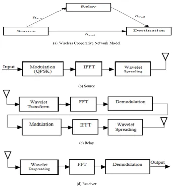
In this work, we investigate the effect of the relay position in a cooperative CI-OFDM system. Wavelet transform is used instead of FFT to realize the CI codes. The system includes one source, one relay and one receiver and it is illustrated in Figure 1.
(a) Wireless Cooperative Network Model
(b) Source
(c) Relay
[image:3.595.125.469.357.726.2](d) Receiver
As seen in the Figure 1, signal is modulated with QPSK while IFFT is used for OFDM. After OFDM, wavelet transform is applied to realize the CI codes, than the signal is being sent to the receiver or the relay over Rayleigh channel. Rayleigh channel model has been used for cooperative diversity in several works [9], [14].
At the receiver, the received signal is depredated by wavelet transform, then FFT is applied for OFDM receiving, and finally QPSK demodulation is applied to the received signal. Whenever the receiver gets all of the copies of the signal, the combining process starts. Relay sends the received information to the receiver with AAF and DAF strategies. For the AAF strategy, the relay doesn’t demodulate signal, because of that wavelet spreading doesn’t employ in the Relay node when using AAF. Receiver combines the received copies of the signals with ERC, FRC and SNRC methods.
8. Results
The Proposed System’s Bit Error Rate (BER) performance is investigated in MatLab environment.
The Proposed System and the Original System are compared by using the same parameters. Simulation parameters are shown in Table 1. Original system means
standard wireless cooperative network without CI spreading.
Table 1. Simulation parameters
Modulation Type QPSK
Channel Rayleigh Fading Channel
Number of Bits 210
Relaying Strategies DAF
Combining Techniques ERC, FRC and SNRC
SNR 0-20 dB
Wavelet Filter Haar
As seen Figure 2, 𝑑𝑑𝑠𝑠,𝑟𝑟 is the distance between source and relay, 𝑑𝑑𝑟𝑟,𝑑𝑑 is the distance between relay and destination, 𝑑𝑑𝑠𝑠,𝑑𝑑 is the distance between source and destination. In Figure 3, Figure 4, Figure 5, Figure 6 and Figure 7, the relay position notation is, respectively: 𝑑𝑑𝑠𝑠,𝑑𝑑:𝑑𝑑𝑠𝑠,𝑟𝑟:𝑑𝑑𝑟𝑟,𝑑𝑑. Relay position is essential for cooperative networks [9].
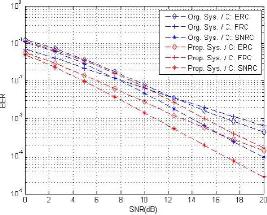
[image:4.595.161.440.399.486.2]In Figure 3, the performance of the proposed system and original system is compared when nodes are located with same distance to each other. The results show that proposed system has better performance for each combiner and SNRC has the best performance.
Figure 2. Notation for Source, Relay and Destination Position
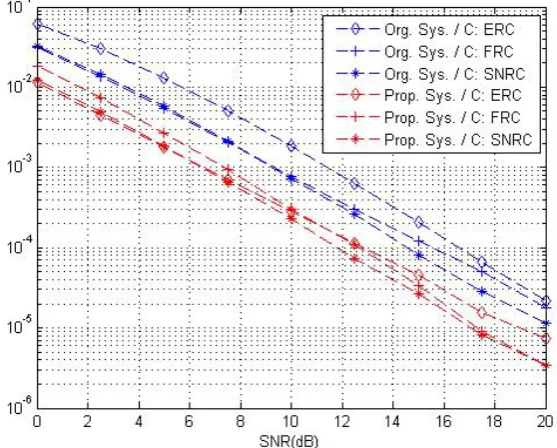
[image:4.595.160.434.517.737.2]In Figure 4, the performance of the proposed system and original system is compared when relay is located right between source and destination. The results show that proposed system has better performance for each combiner and SNRC has the best performance.
Figure 4. Performance of the System when Node Position is 1:0.5:0.5
In Figure 5, the performance of the proposed system and original system is compared when relay is located near of source. The results show that proposed system has better performance for each combiner and SNRC has the best performance.
Figure 5. Performance of the System when Node Position is 1:0.25:0.75
[image:5.595.158.437.422.646.2]Figure 6. Performance of the System when Node Position is 1:0.75:0.25
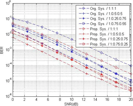
In Figure 7, the performance of the proposed system and original system compared when relay is located in different positions. The results show that the performance has its best when relay is located right between source and destination.
Figure 7. Performance of the System when Relay Located in Different Positions (Combiner: SNRC)
9. Conclusions
In this paper, the effect of relay position in cooperative CI-OFDM with wavelet is analyzed. Combining method is very important for the cooperative network system. In this work, we used ERC, FRC and SNRC. The results show, that the proposed system has its best performance when relay is located right between source and destination. The proposed system has better performance for all type of combiners. Relay location is essential for cooperative network, system performs worse when relay located close
to source or destination, for best performance, the best location for relay is right between source and destination.
REFERENCES
Liu, K. J., Sadek, A. K., Su, W., & Kwasinski, A. (n.d.). [1]
Broadband cooperative communications. Cooperative
Communications and Networking, 569-582.
[image:6.595.159.436.371.591.2]Trivedi, V. K., & Kumar, P. (2017). Carrier Interferometry [2]
Coded Single Carrier FDMA (CI/SC-FDMA) for Next Generation Underwater Acoustic Communication. Wireless Personal Communications, 95(4), 4747-4762. doi:10.1007/s11277-017-4119-1
Anwar, K., & Yamamoto, H. (n.d.). A new design of carrier [3]
interferometry OFDM with FFT as spreading codes. 2006
IEEE Radio and Wireless Symposium.
doi:10.1109/rws.2006.1615214
C. Ciflikli, A. T. Ozsahin, & B. Yazlık, Realization of [4]
Carrier Interferometry OFDM Systems by Wavelet Transform, Artificial Intelligence, Software Engineering and Industrial Application, Thailand, 2015.
Anwar, K., Priantoro, A., Saito, M., Hara, T., Okada, M., & [5]
Yamamoto, H. (n.d.). On the PAPR reduction for wavelet based transmultiplexer. IEEE International Symposium on Communications and Information Technology, 2004. ISCIT 2004. doi:10.1109/iscit.2004.1413829
A. Dubey & A. Bhalla, A Review of Relay selection based [6]
Cooperative Wireless Network for Capacity Enhancement, International Research Journal of Engineering and Technology, vol. 4, pp. 629-633, 2017.
Lu, H., Xu, T., & Nikookar, H. (2012). Cooperative [7]
Communication over Multi-Scale and Multi-Lag Wireless Channels. Ultra Wideband - Current Status and Future Trends. doi:10.5772/48719
Su, W., Sadek, A. K., & Liu, K. J. (2011). Erratum to: [8]
Cooperative Communication Protocols in Wireless Networks: Performance Analysis and Optimum Power Allocation. Wireless Personal Communications, 59(2), 397-397. doi:10.1007/s11277-011-0313-8
Meier, A. (2005). Cooperative diversity in wireless networks. [9]
6th IEE International Conference on 3G and Beyond (05/11182). doi:10.1049/cp:20050189
Chung, Y. (2004). Performance evaluation of adaptive [10]
OFDM with carrier interferometry codes in frequency selective fading channels. 2004 IEEE International
Conference on Communications (IEEE Cat.
No.04CH37577). doi:10.1109/icc.2004.1313151
B. D. Kavaiya, D. Vinay & M. Thumar, Suitability of Carrier [11]
Interferometry Code For NCMC-CDMA Based Cognitive Radio, International Journal of Current Engineering and Scientific Research, vol. 3, pp. 123-129, 2016.
M.R. Megahan & B.K. Harsha, Performance Simulation of [12]
Spreading OFDM for Underwater Communication, International Research Journal of Engineering and Technology, vol. 4, pp. 1165-1168, 2017.
Kumar, P., & Kumar, P. (2012). Performance Evaluation of [13]
DFT-Spread OFDM and DCT-Spread OFDM for Underwater Acoustic Communication. 2012 IEEE Vehicular Technology Conference (VTC Fall). doi:10.1109/vtcfall.2012.6399376
Ikki, S. S., & Ahmed, M. H. (2009). Performance Analysis [14]