-r,:J
c:\
CONTf\.OL DATA
\::I
~COI\PORc\TION
62949100
CDC®
PLATO
®
FLEXIBLE
"
DISK SUBSYSTEM
I
~
1 - - - - 1[J
:"
WARNING
This equipment has been certified to comply with the limits for a Class B computing device pur-suant to Subpart J of Part 15 of FCC Rules. Only peripherals (computer input/output devices, terminals, printers, etc.) certified to comply with the Class B limits may be attached to this computer. Operation with non-certi fied periph-erals is likely to result in interference to radio and TV reception.
This equipment generates and uses radio fre-quency energy and if not installed and used properly, that is, in strict accordance with the manufacturer's instructions, may cause interfer-ence to radio and television reception. It has been type tested and found to comply with the limits for a Class B computing device in accor-dance with the specifications in Subpart J of Part 15 of FCC Rules, which are designed to pro-vide reasonable protection against such inter-ference in a residential installation. However, there is no guarantee that interference will not occur in a particular installation. If this equipment does cause interference to radio or television reception, which can be determined by turning the equipment off and on, the user is encouraged to try to correct the interference by one or more of the following measures:
reorient the receiving antenna
relocate the computer with respect to the receiver
move the computer away from the receiver
plug the computer into a different outlet so that the computer and receiver are on differ-ent branch circuits.
If necessary, the user should consult the dealer or an experienced radio/ television technician for additional suggestions. The user may find the following booklet prepared by the Federal Communications Commission helpful:
"How to Identify and Resolve Radio-TV Inter-ference Problems".
r,ll:\
CONTRPL DATA
\!:I
r:::J
CO!\pOR{\TION
62949100
CDC@
PLATO@FLEXIBLE DISK SUBSYSTEM
. =
-r
-,~-.---.-'-
---'-'---1
REVISION RECORD
---
-~---,..---.---.-.~.--.---~~~ ,-REVISION
01 (08-13-80)
A
(10-03-80)
B-Interim (12-17-80)
C
(01-23-81)
D
(03-02-81) E-Interim (08-13-81)
F
(10-08-81)
G
(01-19-82)
H
(11-23 ... 82)
J
(05-11-83)
62949100 " "
-DESCRIPTION
Preliminary release.
Final release. Includes changes per ECOs 14165, 14190, 14199, 14203, 14246, 14258, 14317, 14323, and 14328.
Manual revised to incorporate ECO 14376.
Manual revised to incorporate ECO's 14469, 14468, 14454, 14391, 14329, 14321, and 14279. Incorporates ECO 14376 (B-Interim) in its final form & makes
technical corrections/changes.
Manual revised to incorporate ECOs 14514 and 14571.
Manual revised to incorporate ECO's 14539, 14591, 14582, 14613, 14663, and 14721.
Manual revised to incorporate ECOs 14742, 14774, and 14838. Also includes technical changes to include media update and product name change.
Manual revised to incorporate ECOs 14885, 14985, 14965, 14820, 14778. Also include~ change in SAM 3, product name change.
Manual revised to incorporate ECOs 15294, 15351, and 15462. FCC certification information also added. Manual revised to incorporate ECOs 14663 (Rev B), 14999, 15634, 15675, 15771, 15786, 15812 and 15867.
Address comments concerning this manual to:
REVISION LETTERS I, 0, Q AND X ARE NOT USED
©1980, 1981, 1982, 1983, 1984, 1985 by Control Data Corporation
Printed in the United States of America
iia
Control Data Corporation
REVISION RECORD (CONTD)
REVISION DESCRIPTION
K Manual revised to incorporate ECOs 15917, 15945, (08-16-83) 16005 and 16060.
L Manual revised to incorporate ECO 16410. (03-20-84)
M Manual revised to incorporate ECOs 16656, 16781, (03-29-85) 16873, and l706l.
-< < ..
Publication No. <62949100
MANUAL TO EQUIPMENT LEVEL CORRELATION SHEET
This manual reflects the equipment configurations listed below.
EXPLANATION: Locate the equipment type and series number, as shown on the equipment FCO log, in the list below. Immediately to the right of the series number is an FCO number. If that number and all of the numbers underneath it match all of the numbers on the equipment FCO log, then this manual accurately reflects the equipment.
EQUIPMENT TYPE
I
SERIESI
WITH FCO'SI
COMMENTS FA501-AIT
-
ECOs 14328, 14376, 1445401
-
ECO 14165 (SiN 141)02
-
ECO 14468 (SiN 274 )03 14571 SIN 401
04 ECO 14663 (SiN 701)
05
-
ECO 14985 (SiN 1115)06
-
ECO 15771 (SiN 4635)07
FA501-B 01
-
ECOs 14238, 14376, 1445401
-
ECO 14165 (SiN 141)02 14571 SiN 401
03 ECO 14663 (SiN 701)
04
-
ECO 14985 (SiN 1115)05
-
ECO 15771 (SiN 4635)06
FA501-C 01
-
ECO 14985, 1504301
-
ECO 15771 (SiN 4635)02
FA501-D 01
-
ECO 1498501
-
ECO 15771 (SiN 4635)02
BR810-A 01
-
ECOs 14240, 14165, 14328,14403
01
-
ECO 14468 (SiN 274)02 ECO 14985 (SiN 391 )
03
BR810-B 01
-
ECOs 14240, 14165, 1432801 ECO 14985 (SiN 391)
02
• iv
MANUAL TO EQUIPMENT LEVEL CORRELATION SHEET (CONTD)
I
EQUIPMENT TYPE
I
SERIESI
XA243-A 01
FTl16-A 01
T
'r---.-I
WITH FCa'SI
COMMENTSI
I
LIST OF EFFECTIVE PAGES
New features, as well as changes, deletions, and additions to informa-tion in this manual are indicated by bars in the margins or by a dot near the page number if the entire page is affected. A bar by the page number indicates pagination rather than content has changed.
PAGE REV
II
PAGE REVII PAGE REVCover 6A-5 F 7-49/7-50 F
WARNING 6A-6 thru 6A-8 G 7-51/7-52 G
Title Page 7-53 thru 7-55 H
iia thru i ic M PROCEDURES 7-56 thru 7-59 K
iii/iv J Section 6B 7-60/7-61 M
v/vi M 6B-l C 8-1 A
vii thru xi G 6B-2 F Comment Sheet M
xii M 6B-3/6B-4 A Mailer
xiii/xiv M 6B-5 thru 6B-9 M Back Cover
PLATO HOTLINE 6B-I0 A
1-1 thru 1-4 G
1-5 F PARTS DATA FOR
2-1 thru 2-3 G PREPRODUCTION
2-4 F UNITS ONLY
3-1 thru 3-3 G 7-1/7-2 A
3-4/3-5 M 7 -3/7-4 J
3-6 thru 3-8 G 7-5/7-6 G
3-9 F 7-7 M
4-1/4-2 F 7-8 A
4-3 C 7-9 M
4-4 A 7-10 A
4-5 F 7-11 thru 7-16 C
4-6/4-7 G 7-17 thru 7-20 E
4-8 A
4-9 F PARTS DATA FOR
4-10/4-11 A PRODUCTION UNITS
4-12 F ONLY
4-13 C 7-21/7-22 M
4-14 F 7-23 thru 7-28 J
4-15 G 7-29/7-30 M
5-1 A 7-31/7-32 G
5-2 thru 5-16.2 J 7-33 thru 7-38 L
5-17 J 7-38.1/7-38.2 L
5-18 thru 5-22 A 7-38.3 thru 7-38.8 M 5-23 thru 5-25 K 7-39 thru 7-42 J
6-1 thru 6-3 A
6-4/6-5 F COMMON PARTS DATA
6-6 A APPLICABLE TO BOTH
6-7 F PREPRODUCTION AND
PRODUCTION UNITS
SAMS Section 6A 7-43 thru 7-47 D
6A-l A 7-48 J
6A-2 F 7-48.1 thru 7-48.3 J
6A-3 C 7-48.4 thru M
16A-4 A 7-48.16
II
PREFACE
This manual provides information to aid in the installation, checkout, and maintenance of the CDC@ PLATO@ Flexible Disk Subsystem. Information is provided for both on-site and tech-nical support use. The subsystem provides flexible disk storage
capability to an Information Systems Terminal (1ST-II and 1ST-III).
Product number correlation for the various subsystem configura-tions and associated memory opconfigura-tions is as follows:
Equipment Number FA501-A
BR810-A
FA501-B
BR810-B
FA501-C
FA501-D
XA243-A
FTl16-A
Descrietion
Primary Flexible Disk Subsystem, 60 Hz, 120 Vac.
Secondary Flexible Disk Drive, 60 Hz, 120 V ac.
Primary Flexible Disk Subsystem, 50 HZ, 220/240 Vac.
Secondary Flexible Disk Drive, 50 Hz, 220/240 V ac.
Control Data 110 Primary FD Subsystem, 60 Hz, 120 Vac.
Control Data 110 Primary FD Subsystem, 50 Hz, 220/240 Vac.
Additional 16K by 8-bit RAM Option (up to three RAM options may be added to the FA501-A/B). The FA501-C/D has 64K RAM standard.
Terminator assembly for 1ST parallel I/O channel.
Organization of this manual is divided into eight major sections: Section 1 - General Description
Section 2 - Operation
Section 3 - Installation and Checkout Section 4 - Theory of Operation
Section 5 - Diagrams Section 6 - Maintenance Section 7 - Parts Data Section 8 - Wire Lists
I
Other manuals providing reference and operator information on the flexible disk subsystem, maintenance information on the
flexible disk drive assembly, and maintenance information on the 1ST terminal are listed as follows. All manuals may be ordered from:
Control Data Corporation
Literature and Distribution Services 308 North Dale Street
St. Paul, Minnesota 55103
Title Publication Number
PLATO@ Flexible Disk Subsystem Operators Guide
9406 Flexible Disk Drive Assembly Hardware Maintenance Manual Information Systems Terminal II
Hardware Maintenance Manual (1ST-II) Information Systems Terminal III
Hardware Maintenance Manual (1ST-III) Engineering Services Diagnostic Disk for
PLATO@ Flexible Disk Subsystem Operators Manual
Control Data 110 Microcomputer System Installation and Diagnostics Manual Control Data 110 Software Users Manual
In addition to these publications, an instructional disk and user's installation guide are available as
Micro Plato Instructional Flexible Disk Micro Plato User's Installation Guide
62940005
77614903
82100083
62940007
62940015
62940024 62940025
flexible follows: 76773000 A 76368339
The disk and the guide may be ordered, using an Education Order Form, from:
Order Administrator Education Company 8100 34th Avenue South
P.O. Box 0
Minneapolis, Minnesota 55440
Diagnostic disks to support CDllO and Micro Plato are available as follows:
CDllO Users Diagnostic Flexible Disk Engineering Services Diagnostic Disk
Control Data Corporation
66314929 76774999
Software Development and Distribution (ARH230) 4201 Lexington Avenue North
Or telephone:
Arden Hills, Minnesota 55112
Gerald J. Ferber, ARH230, Software Distribution
.Phone 612-482-3744 Control Net 235-3747
The 1ST II and the 1ST III have been approved by the Federal Communications Commission (FCC) as not being harmful to the telephone network when connected directly to the telephone
lines. Instructions for fully complying with Part 68, FCC Docket 19528 can be found in the Site and Support manuals that accompany the particular terminal being used.
I
I
1.
2.
3.
CONTENTS
GENERAL DESCRIPTION
Subsystem Confi;uration • • • • • • • • • • • • • • • 1-1 Primary Flexible Disk Subsystem • • • • • • • • • 1-2 Control Data 110 Primary Flexible Disk Subsystem • 1-2 Secondary Flexible Disk Drive • • • • • • • • 1-2 RAM Expansion Feature • • • • • • • • • • • • 1-2 ROM Expansion Feature (Future Availability) • 1-2 Media • • • • . • • • • • . . • • . . • • • • . • 1-3 Equipment Specifications • • • • • • • • • • • • • • 1-4
OPERATION
Volta;e Select Switch • • • • • • • • • • • • • • 2-1 Power On/Off Switch/Circuit Breaker • • • • • • • • • 2-1 Device Address Strap (Primary Units Only) • • • • 2-2 Master Reset Switch (Primary Units Only) • • • • • • 2-2 Dia;nostic Control Switches (Primary Units Only) • • 2-2 Switch 20 • • • • • • • • • • • • • • • • 2-3 Switch 21 • • • • • • • • • • • • • • • • • • 2-3 Switch 22 . . . . . . 2-3 Switch 23 • • • • • • • • • • • • • • • • 2-3 Switch 24 and 25 • • • • • • • • • • • 2-3 Switch 26 • • • • • • • • • • • • • • 2-4 Switch 27 • • • • • • • • • • • • • • • • 2-4 LED Indicators • • • • • • • • • • • • • • • • • 2-4
INSTALLATION AND CHECKOUT
Packa;in; • • • • • • • • • • • • • • • • • • • • • • 3-1 Installation • • • • • • • • • • • • • • • • • • 3-1.1
Subsystem Installation • • • • • • • • • • • • • • 3-2 RAM Option Installation • • • • • • • • • • • 3-6 Checkout • • • • • • • • • • • • • • • • • • • • 3-7
4. THEORY OF OPERATION
x
AC Power Entry Panel • • • • • • • • • • • • • • 4-2 Power Supply • • • • • • • • • • • • • • • • • • 4-2 Backplane • • • • • • • • • • • • • • • • 4-3 Flexible Disk Drive (FDD) Assembly • • • • • • • 4-4 Controller Board (Primary Units Only) • • • • 4-6 Z80A Microprocessor • • • • • • • • • • • • • • • 4~8
9517A-4 Direct-Memory-Access (DMA) Controller • • 4-8 l791A-02 Flexible Disk Controller (FDC) • • • • • 4-9 2716 Erasable Pro;rammable Read-Only Memory (EPROM)4-9 Z80 Counter/Timer Circuit (CTC) • • • • • • • 4-10 9519 Interrupt Controller • • • • • • • • • • • • 4-11
External Interface Pin Assignments • • • • • • • 4-12 Internal Connector Pin Assignments • • • • • • • • • 4-12
5. DIAGRAMS
Schematic Diagram, 9BED • • • • • • • • • • • • • • • 5-2 Schematic Diagram 9BKD (PFDS Power Supply) • • • • • 5-18 Schematic Diagram (9BMD) (FDD Controller Backplane) • 5-21 50/60 Hz A.C. Power Wiring • • • • • • • • • • • • • 5-22 Schematic Diagram (lAFD) (PFDS Power Supply) • • • • 5-23
6. MAINTENANCE
General Maintenance Information • • • • • • • • • 6-1 Suggested Emergency Maintenance Procedure • • • • 6-1 Before Leaving for Customer Site • • • • • • • 6-2 Upon Arriving at Customer Site • • • • • • • • 6-2 Safety Precautions • • • • • • • • • • • • • • • • 6-3 Maintenance Tools apd Materials • • • • • • • • • 6-3 MOS Circuit-Handling Precautions • • • • • • • • • 6-3 Maintenance Aids • • • • • • • • • • • • • • • 6-4 Location of Major Assemblies • • • • • • • • • • • 6-4 Diagnostic and Corrective Maintenance • • • • • • • • 6-4 Diagnostic Self-Test Routines • • • • • • • • • • 6-4 LED Test • • • • • • • • • • • • • • • • • • • 6-5 Test 0 - ROM Checksum • • • • • • • • • • • 6-5 Test 1 - RAM Test • . • • • • • • . • • • • • • 6-6 Test 2 - Interrupt Generator • • • • • 6-6 Test 3 - Flexible Disk Controller • • • • • • • 6-6 Test 4 - DMA Test • • • • • • • • • • • • • • • 6-6 Test 5 - I/O Loopback Test • • • • • • • • • • 6-6 Test 6 - CTC Test • • • • • • • • • • • • • • • 6-6 Test 7 - Writing and Reading the Disk • • • • • 6-7 DIAG Flexible Disk Diagnostic Tests • • • 6-7 Explanation of SAM Format • • • • • • • • • • • • 6-7 Organization of SAMs and Procedures • • • • • 6-7
62949100 G
Procedure 1 - Power Application/Removal • • 6B-l Procedure 2 - Flexible Disk Installation/
Removal • • • • • • • • • • • • • • • • • • • 6B-2 Procedure 3 - Front Panel and Cabinet Hood
Removal/Replacement • • • • • • • • • • • • • 6B-4 Procedure 4 - Controller Board Removal/
Replacement • • • • • • • • • • • • • • • • • 6B-5 Procedure 5 - Power Supply Removal/Replacement. 6B-6 Procedure 6 - Disk Drive Unit Removal/
Replacement • • • • • • • • • • • • • • • • • 6B-8
I
7. PARTS DATA
8.
(Pre-Production Units Only)
SPL Primary Flexible Disk Subsystem • • • • • • • • • 7-3 SPL Secondary Flexible Disk • • • • • • • • • • • • • 7-5 Genealogy Chart Primary Flexible Disk Subsystem 60 Hz 7-7 Genealogy Chart Primary Flexible Disk Drive 60 Hz • • 7-S Genealogy Chart Primary Flexible Disk Subsystem 50 Hz 7-9 Genealogy Chart Secondary Flexible Disk Drive 50 Hz 7-10 PLATO Flexible Disk (TLA) • • • • • • • • • • • • • • 7-11 AC Entry Assy, Flex Disk • • • • • • • • • • • • • • 7-17
(Production Units Only)
SPL FA501A/C (60 Hz Primary) • • • • 7-21
SPL FA501B/D (50 Hz Primary) • • • • • • • • • • 7-23 SPL BRSIOA (60 Hz Secondary) • • • • • • • • 7-25 SPL BRSIOB (50 Hz Secondary) • • • • • • • . • • 7-27 Genealogy Chart (60 Hz Primary) • • • • • • • • • 7-29 Genealogy Chart (50 Hz Primary) • • • • • • • 7-30
Genealogy Chart (60 Hz Secondary) 7-31
Genealogy Chart (50 Hz Secondary) • • • • 7-32 PLATO Flexible Disk (TLA) • • • • • • • • • • • • 7-33 CDllO Flexible Disk (TLA) • • • • • • 7-3S.5 AC Entry Assembly • • • • • • • • • • • • • • • • 7-39
(Common Parts Data)
P.C. Card Assembly, 9BED (Disk Controller)
· · ·
7-43 P.C. Card Assembly, 9BED-3 (Disk Controller)· ·
·
·
7-48.4 P.C. Card Assembly, 9BED-4 ( Disk Controller)· ·
7-48.8 P.C. Card Assembly, 9BED w/Full Memory· · ·
·
7-48.12 Card Assembly Controller Module w/Full Memory· · · ·
7-48.14 P.C. Card Assembly, 9BKD •· · ·
· · · ·
· ·
7-48.16 P.C. Card Assembly, lAFD· ·
· ·
· · ·
7-52 P.C. Card Assembly, 9BMD·
· ·
·
·
·
· · · ·
·
·
7-60WIRE LISTS
FIGURES
1. GENERAL DESCRIPTION
1-1 PLATO Flexible Disk Subsystem • • • • • • • • • 1-1 1-2 'PFDS Primary and Secondary Unit Details • • 1-3
'2. OPERATION
2-1 Control and Indicator Locations • • • • • • • • 2-1
3. INSTALLATION AND CHECKOUT
3-1 Flexible Disk Subsystem Packaging . . . • • . • 3-2.1 3-2 Controller Board Switches and Indicators • 3-4 3-3 I/O Cable and Terminator Installation • • • 3-5 3-5 Power Supply Voltage Indicators • . • . . . . • 3-7
4. THEORY OF OPERATION
4-1 Major Elements of Subsystem • • . . . • • • 4-1 4-2 Subsystem Block Diagram • • • • • . . • 4-2 4-3 Drive Assembly Functional Block Diagram . • 4-5 4-4 Controller Board Block Diagram • • • . • • 4-7 4-5 External Wiring of the CTC for Head-Load Timing 4-10 4-6 External Wiring of the CTC for Real-Time Clock 4-11 4-7 Flexible Disk Interrupt Network. • • • • . 4-12 4-8 Internal Connector Pin Assignments . • . • . . 4-15 6. MAINTENANCE
6-1 Location of Assemblies in Subsystem
·
·
·
· ·
·
6-5 6-2 SAM Example.
. . .
· ·
· · ·
·
·
·
6-8 6B-l Power On/Off Switch Location· ·
·
..
0 6B-l 6B-2 Disk Installation/Removal·
·
· ·
· ·
·
6B-2 6B-3 Front Panel and Cabinet Hood Mounting Details·
6B-4 6B-4 Controller Board Layout· ·
·
0· ·
·
·
· ·
6B-56B-4.1 Controller Board Layout Model 9BED-4
· · ·
6B-6 6B-5 Power Supply Voltage Adjustments· · ·
·
0 0·
6B-7 6B-6 Disk Drive Unit Installation·
· · ·
· ·
·
6B-9 6B-7 Drive Pulley Details.
·
· · ·
·
· · ·
·
·
6B-IOTABLES
1. GENERAL DESCRIPTION
1-1 Equipment Specifications • • • . • • • • • • • 1-4
4. THEORY OF OPERATION 4-1
4-2
Parallel I/O Channel Pin Assignments • • • • Secondary Drive Unit Channel Pin Assignments
7. PARTS DATA
7-1 Explanation of Column Headings on Assembly
• 4-13 . 4-14
Parts Lists • • . • • • • • • • • • • • • • • 7-1
62949100 M xiii/xiv
Should difficulties be encountered in installing, testing, or running this equipment, you may obtain assistance by contacting your CDC sales representative for the telephone number applicable to your installation. After obtaining the number, write it here for future reference:
TELEPHONE NUMBER
---GENERAL DESCRIPTION 1
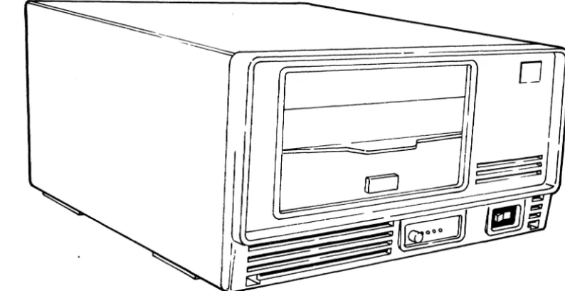
This section provides a general description of the PLATO Flexi-ble Disk Subsystem (PFDS) configuration including the related equipment specifications. The PFDS is a Z80
microprocessor-based programmable storage subsystem that is intended for use by
an Information Systems Terminal. The subsystem interfaces with
I
the terminal via the,PLATO parallel I/O channel. Refer tofigure 1-1 for an exterior view of the subsystem.
o
03892
Figure 1-1. PLATO Flexible Disk Subsystem
SUBSYSTEM CONFIGURATION
The PFDS is configured as two basic versions: • Primary Flexible Disk Subsystem
• Secondary Flexible Disk Drive
I
[image:22.617.92.489.284.488.2]I
Each version is available as either a GO-Hz or 50-Hz product/ equipment. Refer to the preface for product/equipment number correlation.
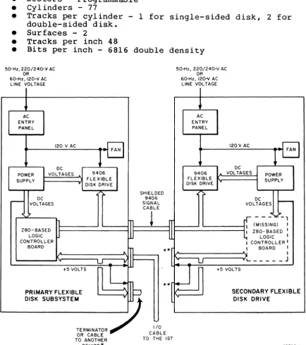
The subsystem can consist of a single primary unit or a primary unit and one secondary unit. The two units (primary and
secondary) are interfaced by attaching the signal lines of both 9406 Disk Drives together via a 50-pin interconnecting I/O
cable. The net effect is that the controller logic board of the primary unit is interfaced to both 9406 Disk Drives connected in parallel as shown in figure 1-2.
PRIMARY FLEXIBLE DISK SUBSYSTEM
The Primary Flexible Disk Subsystem contains a CDC 9406 Flexible Disk Drive, a 50-Hz or 60-Hz ac power entry panel, a
mother-board backplane, a dc power supply, and a Z80-based controller logic board.
CONTROL DATA 110 PRIMARY FLEXIBLE DISK SUBSYSTEM
The Control Data 110 Primary Flexible Disk Subsystem contains a CDC 9406 Flexible Disk Drive, a 50-Hz or 60-Hz ac power entry panel, a mother-board backplane, a dc power supply, and a
Z80-based controller logic board with 64K of RAM.
SECONDARY FLEXIBLE DISK DRIVE
The Secondary Flexible Disk Drive is identical to a primary unit except that the Z80-based controller logic board is removed.
RAM EXPANSION FEATURE
The standard subsystem random-access memory consists of 16K
8-bit words in the FASOI-A/B. The RAM size may be expanded to a total of 64K 8-bit words in 16K-word increments. Each 16K RAM option consists of eight 16-pin integrated circuits (ICs). IC sockets are provided on the controller logic board for installa-tion of the RAM chips. The FASOI-C/D has 64K as standard.
MEDIA
The recommended media for use in the subsystem is a cial flexible disk (double-sided, double-density). ble disks have the following characteristics:
good commer-These
flexi-• Index - 1
• Sectors - Programmable • Cylinders - 77
• Tracks per cylinder - 1 for single-sided disk, 2 for double-sided disk.
• Surfaces - 2
• Tracks per inch 48
• Bits per inch - 6816 double density 50-Hz, 220/240-V AC
OR 60-Hz, 120-V AC
LINE VOLTAGE
AC ENTRY PANEL
120 V AC
DC
POWER VOLTAGES
SUPPLY
DC
r - - VOLTAGES
1 ZBO- BASED
J
LOGIC CONTROLLER BOARD.
FAN 9406 FLE XIBLE..
DISK DRIVE ;.. W +5 VOLTS1
PRIMARY FLEXIBLE SHIELDED 9406 SIGNAL CABLEn
~
~
~
**f
"
JI
..
[
:11
DISK SUBSYSTEM
"'.,,""' -7
OR CABLEc:~o"
TO ANOTHER TO THE 1ST
50-Hz, 220/240-V AC OR
60-Hz, 120-V AC LINE VOLTAGE
AC ENTRY PANEL
120 V AC
- FAN
OC
9406 VOLTAGES POWER
FLEXIBLE SUPPLY
DISK DRIVE
:=.
DC ~
VOLTAGES
.
- -
-~-,I (MISSING)
,
ZBO-BASED I I
LOGIC I , CONTROLLER I
,
BOARD,
,
)'L.. _____ J
U
U
+5 VOLTSSECONDARY FLEXIBLE
" DISK DRIVE
DEVICE* 03798-1
I
I
*The other device could be another Primarx Flexible Disk
I
Subsystem, Graphic Printer, etc.**These connectors are not used.
Figure 1-2. PFDS Primary and Secondary Unit Details
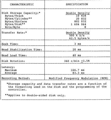
[image:24.618.97.532.159.649.2]EQUIPMENT SPECIFICATIONS
Equipment specifications for the subsystem are listed in table 1-1.
TABLE 1-1. EQUIPMENT SPECIFICATIONS
CHARACTERISTIC SPECIFICATION
Dimensions:
Height 202.85 mm (7.99 in)
Width 381 mm (14.99 in)
Depth 502.5 mm (19.78 in)
Weight:
I
FA501-A/C (60-Hzprimary) 16.78 kg (37 1b) maximum FA501-B/D (60-Hz primary) 20.19 kg (44.51 1b) maximum BR810-A (60-Hz secondary) 16.33 kg (36 1b) maximum BR810-B (50-Hz secondary) 19.73 k9_ (43.5 1b) maximum Power Requirements:(Nominal)
FA501-A/C 120 V ac, 60 HZ, 1.4 A, 0.18 kW max imum FA501-B/D 220/240 V ac, 50 Hz, 0.8 A, 0.19 kW
I
maximum
BR810-A 120 V ac, 60 Hz, 1.2 A, 0.16 kW
maximum
BR810-B 220/240 V ac, 50 Hz, 0.68 A, 0.16 kW
maximum Temperature:
Operating 10°C to 32°C (50°F to 90°F)
Nonopera ting -34°C to 66°C (-30°F to 150°F)
Change/h 6.7°C (12 ° F)
Relative Humidity:
Operating 10% to 80%
Nonoperating 5% to 95%
Change/h 10%
Operating Altitude: - 3000 m (9850 ft) maximum Heat Dissipation (Air) :
I
555 Btu/h (161.3 W) maximum, fan cooled [image:25.617.63.560.143.667.2]TABLE 1-1. EQUIPMENT SPECIFICATIONS (CONTD)
---_.-CHARACTERISTIC
-I
~PE
CIFICATION-.---.----.---Disk Storage Capacity:* Bytes/Track
Bytes/Cylinder** Bytes/Surface Bytes/Disk** Bits/Byte
Transfer Rate:*
-Seek Time:
Dou
Dou 5 6
ble Densi~
raUb
20 832 802 032 1 604 064 8
ble Density 00 k b/s 2.5 bytes/s
3 ms
---Head Stabilization Time: 20 ms
Head Load Time: 40 ms
IDisk Rotation: 360 r/min +3.5%
/LatenCy:
Maximum 166.7 ms
Average 83.3 ms
_R_e_c_o_r_d._i_n..:,g __ M_e_t_h_o_d_: _____ L2!od ified Frec:Iuency Modulation_i~~~_)_
*Storage capacity and data transfer rates are a function of the formatting used on the disk and the programming of the controller.
**Applies to double-sided disk only.
62949100 F 1-5
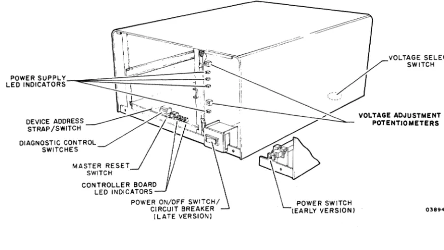
[image:26.613.100.571.84.591.2]OPERATION
This section describes the controls and indicators of the flexi-ble disk subsystem. Locations are shown in figure 2-1. Refer to the Micro Plato user's installation guide and Micro Plato instructional flexible disk or the Control Data 110 Microcom-puter System User Installation and Diagnostics Manual for
information on associated operating programs (see preface for publication/part numbers).
_
~~d~~/=---==---~~==-~::tJ-'~~
POWER SUPPLY ""
LED INDICATORS ~ I "
II ,I ~r
VOLTAGE SELECT
___
~
s.n,"
_
~LTA.E
,"'"""!NT
~-~--- '~
DEVICE ADDRESS _______ _ / ) ~ ___ ~~
STRAP/SWITCH ... ~
-DIAGNOSTIC CONTROL SWITCHES
MASTER RESET SWITCH
CONTROLLER BOARD LED INDICATORS
...
POTENTIOMETERS~
~
POWERS"TC"
(EARLY VERSION) 03894-2
Figure 2-1. Control and Indicator Locations
VOLTAGE SELECT SWITCH
The voltage select switch is present on 220/240-V, 50-Hz units only. The switch is located on the bottom of the cabinet and selects taps on the transformer primary winding to match the input site voltage available. A metal plug covers the access hole.
POWER ON/OFF SWITCH/CIRCUIT BREAK~
Two versions of the Power On/Off switch/circuit breaker exist. Early units have the switch/circuit breaker mounted toward the
62949100 G 2-1
2
I
[image:28.617.86.522.225.471.2]rear of the unit with a connecting rod attached to a push/pull control knob at the front of the unit. Power is applied by pulling the knob forward and power is removed by pressing the knob in. Later units have a rocker switch/circuit breaker mounted on the front of the unit.
A power application initializes all internal control logic circuits, and if bit 27 of the diagnostic control switches is down, initiates the self-test diagnostics.
The circuit breaker provides necessary overload protection for the subsystem.
DEVICE ADDRESS STRAP (PRIMARY UNITS ONLY)
The subsystem device address is wired to position 7 by the device address strap at the front of the controlle~ board. In early units the subsystem device address is established by a la-position binary-coded-decimal rotary switch at the front of the controller board.
MASTER RESET SWITCH (PRIM~RY UNITS ONLY~
Pressing the Master Reset switch reinitializes the operating program. Holding the switch pressed more than three seconds, reinitiates the self-test diagnostics (if selected), and reloads the operating program into RAM memory. The operating program is loaded from the flexible disk if available. If a flexible disk is not present, the flexible disk subsystem trys to load from the PLATO system.
DIAGNOSTIC CONTROL SWITCHES (PRIMARY UNITS ONLY~
There are eight switches on the front of the controller board that provide manual control of the program and self-test
diagnostics. Diagnostic test descriptions are provided in
section 6. Control functions selected by these switches are as follows:
SWITCH 20 - Not used
SWITCH 21
• Up - Allows result of detailed memory test to be displayed in LEDs per switch 22 setting.
• Down - Bypasses displaying result of detailed memory test selected by switch 22.
SWITCH 22
• Up - Allows failing memory IC within a RAM bank to be displayed in LEDs. Switch 21 must be in up position to view this display. Also note that for subsystems having more than 16K of RAM, failing memory bank must first be determined by having switch 22 down.
• Down - Allows failing memory bank to be displayed in LEDs. Switch 21 must be in up position to view this display.
SWITCH 23
• Up - Bypasses test 7 (write/read on disk) of diagnostics. • Down - Enables execution of diagnostic test 7.
SWITCH 24 and 2 5
These switches define what banks of RAM are installed:
Swi tch 25 Down Down Up Up
Switch 24 Down Up Down Up
RAM BANKS AVAILABLE 1 (l6K) 1, 2 (32K) 1, 2, 3 (4 8K) 0, 1, 2, 3 (64K)
ADDRESS RANGE (HEX) 4000 - 7FFF 4000 - BFFF 4000 - FFFF 0000 - FFFF
All FA501-C/D units have 64K RAM; both switches 24 and 25 must be up.
62949100 G 2-3
SWITCH 26
• Up - Allows looping on diagnostic tests.
• Down - Does not loop on diagnostics.
SWITCH 27
• Up - Bypasses diagnostic test execution.
• Down - Enables execution of the diagnostics except when
switch 20 is up.
LED INDICATORS
Primary units have four red LED indicators on the controller board that are visable through holes in the front panel. The LEDs are used by the self-test diagnostics to indicate detected
errors. LED 23 (leftmost) indicates a diagnostic error and
LEDs 20 through 22 identify the failing memory bank or IC as determined by the settings of switch 20, 21, 22, and 27
of the diagnostic control switches.* At successful completion of the diagnostics, LED 20 is assigned as the power-on
indicator. These LEDs are also user programmable.**
Both primary and secondary units have four red voltage LEDs on the power supply PC board. The front panel must be removed to
view the indicators. These LEDs indicate presence of +24 V, +12
V, +5 V, and -5 V at the power supply outputs. Note that a lit LED does not conclusively indicate that the correct voltage is present, only that there is sufficient voltage to bias the device on.
Two adjustment potentiometers are also on the power supply PC
board. These provide for adjusting the +24-V and +5-V power
supply outputs.
*LEDs 20 through 22 define which test section has failed. If diagnostic control switch 21 is up and there is a memory error, then LEDs 20 through 22 identify the failing memory bank or IC depending on setting of switch 22.
**After completion of the self-test diagnostics, the operating system uses LED 23 as an Error indicator, LED 22 as a Read indicator, LED 21 as a Write indicator, and LED 20 as a
Power~on indicator.
2-4
INSTALLATION AND CHECKOUT
This section provides information on packaging, installation, and checkout of the flexible disk subsystem.
PACKAGING
CAUTION
Control Data 110 Terminal Subsystem users must use installation, check-out, and diagnostics procedures described in Control Data 110 Micro-computer System User Installation and Diagnostics Manual.
CAUTION
Observe MOS circuit handling precau-tions (described in section 6 of this manual) when handling or pack-aging the controller board.
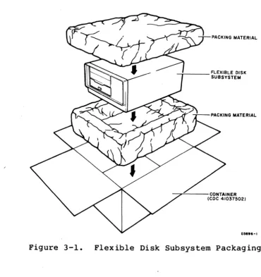
The flexible disk subsystem is packaged for shipment using
foam-in-place chemicals (figure 3-1). If the subsystem is to be reshipped it must be packaged as i t was originally received from the factory. Use the existing packing materials or if not
available, order new packing materials from CDC Corporate Traffic. Request pre-formed packing materials for the FA50l/BR8l0 per packing instructions 41039800. Packaging materials may be obtained from:
Control Data Corporation Corporate Traffic 8100 34th Avenue South Minneapolis, Minnesota 55440
When returning other assemblies for repair, use the packaging material that the spared assembly was shipped in.
62949100 G
NOTE
When shipping any disk drive be sure to insert the cardboard head-protect flexible disk into the drive unit.
3-1 3
I
INSTALLATION
This subsection provides information for installing the flexible
disk subsystem (primary and secondary units) and for field
installation of the RAM options if applicable to the primary
unii.
3-2
NOTE
Selective FCO CD14283 must be
in-stalled if the disk is to be used on
an 1ST-II with a serial number below
3000.
This FCO provides a new 'ROM
with a disk loader.
The part number
for FCO CD14283 is 66202932.
- j -_ _ _ FLEXIBLE DISK SUBSYSTEM
----,,---CONTAINER (CDC 41037502)
01."-1
Figure 3-1.
Flexible Disk Subsystem Packaging
SUBSYSTEM INSTALLATION
Install the flexible disk subsystem per the following.
Procedure numbers used in the steps refer to specific procedures
contained in section 6B of this manual.
1. Unpackage subsystem (refer to figure 3-1), and move to
desired location.
Remove cardboard head-protective
flexible disk from drive unit and store with subsystem
packaging materials.
Note that secondary unit may be
stacked on top of primary unit or primary unit may be
stacked on top of secondary unit or units may be placed
side-by-side if desired.
2. Inspect for any shipping damage.
3. For 50-Hz units, verify that voltage Select switch
(bottom of cabinet, metal plug covers access hole) is set
[image:34.613.131.501.65.457.2]correctly to match site ac primary input voltage as follows:
Switch position VoltaS{e RanS{e
120 V Not Used
220 V 191 V to 235 V
240 V 208 V to 257 V
NOTE
Cover unused voltage designation on ID plate (figure 3-4) with black tape.
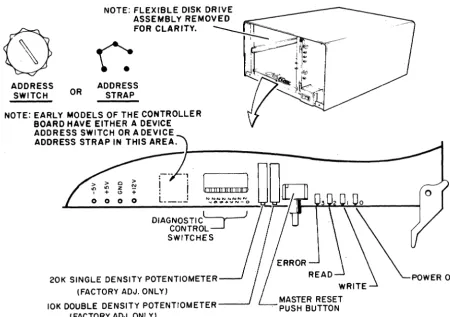
4. This step applies to primary flexible disk units only. Remove front panel of unit (procedure 3) and locate switches at front of controller board (figure 3-2).
• Check that device address strap is wired to address 7 as in figure 6B-4. (Set device address switch to address 7 if unit has switch.)
• Set Diagnostic Control Switches as follows:
62949100 G
Switch 20 - Not used
Switch 21 - Down (bypasses displaying result of detailed memory test selected by switch 22).
NOTE
Switch 21 must be down to display the failing test number in the LEDs. If a test 1 (memory test) failure is detected, place switch 21 up to
display the specific memory bank or IC failure as selected by switch 22.
Switch 22 - Down (allows failing memory bank to be displayed in LEDs).
Switch 2 3 - Up (disables running test 7 of resident diagnostics).
Switch 24 and 2 5 - For FA50l-C/D set both switches
up. For FA50l-A/B set to RAM memory size available as follows (each
XA243-A option adds 16K of RAM): switch 25
Down Down Up Up
Switch 24 Down Up Down Up
RAM Size 16K (Standard) 32K (Option) 48K (Option) 64K (Option)
I
ADDRESS SWITCH
Switch 26 - Down (does not loop on diagnostics). Switch 27 - Down (enables running diagnostic tests).
OR ADDRESS STRAP
NOTE: EARLY MODELS OF THE CONTROLLER BOARD HAVE EITHER A DEVICE ADDRESS SWITCH OR A DEVICE ADDRESS STRAP IN THIS AREA.
o > Z N
" +
o 0 0 0
t
II II!! 1111 !!,,)NNNNNNNN
.... OIU1 ... ~N-O
DIAGNOSTIC~ CONTROL~ SWITCHES
20K SINGLE DENSITY POTENTIOMETER (FACTORY ADJ. ONLY)
POWER ON
3-4
10K DOUBLE DENSITY POTENTIOMETER---' (FACTORY ADJ. ONLY)
MASTER RESET PUSH BUTTON
Figure 3-2. Controller Board Switches and Indicators
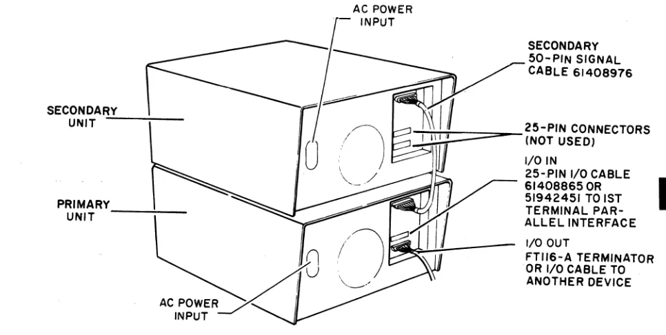
5. Refer to figure 3-3 and install I/O cable and terminator assembly per the following as applicable:
NOTE
A standard 25-pin RS-232-C compatible cable CANNOT be substituted for the specified I/O cable.
• Primary flexible disk unit - If there are no other devices attached to 1ST parallel interface channel, connect 25-pin I/O cable (CDC 61408865 or 51942451) from parallel interface channel of 1ST terminal to either 25-pin I/O connector at rear of flexible disk
unit. Connect terminator assembly (type FTl16-A) to other 25-pin I/O connector of drive unit. Tighten retaining screws to hold cable connectors in place.
03897-3
[image:37.621.73.523.124.440.2]If other devices are already attached to 1ST parallel interface channel, remove terminator assembly from
last device on channel and connect 25-pin I/O cable
I
(CDC 61408865 or 51942451) between last device andeither 25-pin connector at rear of flexible disk unit. Install the terminator assembly to other I/O connector of drive unit. Tighten retaining screws to hold cable connectors in place.
• Secondary flexible disk unit - Connect 50-pin I/O cable (CDC 61408976) between 50-pin connectors of primary and secondary flexible disk units. Note that 25-pin I/O connectors are not used on secondary unit. • Verify that no flexible disk is installed in drive
un it (s) •
SECONDAR.;..;Y_-;.-_ _ UNIT
AC POWER INPUT
SECONDARY 50-PIN SIGNAL CABLE 61408976
~::ttrtt=:::::::;:::::::o_25-PIN CONNECTORS
C. (NOT USED) I/O IN
25-PIN I/O CABLE , 51942451 TO 1ST PRIMARY
UNIT - - - : - -
~
614088650R
I TERMINAL
PAR-1/"' ALLEL INTERFACE
(\
" AU
ACPOWERx'
I
INPUTif
I/O OUT~ 18 FTII6-A TERMINATOR
~'f OR I/O CABLE TO ANOTHER DEVICE
Figure 3-3. I/O Cable and Terminator Installation
6. Connect ac power cord to rear of unit, check that power on/off switch is in off position and plug ac line cord
into site outlet.
62949100 M
WARNING
Applying improper voltage to the flexible disk subsystem can damage components. Read label on back of unit for proper voltage and
frequency.
3-5
[image:38.612.91.574.275.518.2]RAM OPTION INSTALLATION (Applies to FASOl-A/B Only)
Perform the following steps to install a 16K by a-bit RAM option (XA243-A). Up to three RAM options can be installed in a
primary unit to expand the memory size to a total of 64K a-bit words. Observe MOS circuit handling precautions described in
section 6 when installing RAM ICs.
1. Remove controller board from unit.
2. Install RAM ICs in existing sockets on controller board as follows:
• First RAM option in locations Cl, C2A, C2B, C3, C4A, C4B, CS, and C6.
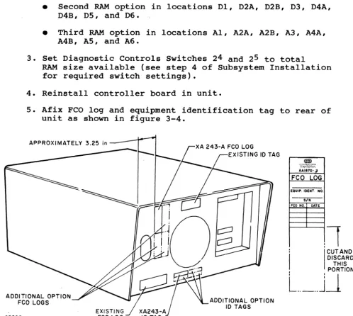
• Second RAM option in locations Dl, D2A, D2B, D3, D4A, D4B, DS, and D6.
• Third RAM option in locations AI, A2A, A2B, A3, A4A, A4B, AS, and A6.
3. Set Diagnostic Controls Switches 24 and 2 5 to total
RAM size available (see step 4 of Subsystem Installation for required switch settings).
4. Reinstall controller board in unit.
5. Afix FCO log and equipment identification tag to rear of unit as shown in figure 3-4.
APPROXIMATELY 3.25 in
~~
~<t,~~~~
AA1870·a
FCO LOG
EQUIP. IOENT. NO. SIN FCO NO. DATE
,
,
1
:
I
CUT ANDI
DISCARD THIS , PORTIONL
.. _ ..
J~
ADDITIONAL OPTION
FCO LOGS ADDITIONAL OPTION
10 TAGS
03895
Figure 3-4. RAM Option FCO Log and ID Tag Placement
[image:39.620.53.552.251.698.2]CHECKOUT
Perform the following steps to checkout the operational
capability of the flexible disk subsystem including any
installed options.
If any problems are encountered, refer to
the SAM listings in section 6A for corrective action.
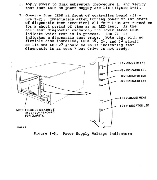
1. Apply power to disk subsystem (procedure 1) and verify
that four LEDs on power supply are lit (figure 3-5).
2. Observe four LEDS at front of controller board
(fig-ure 3-2).
Immediately after, turning power on (at start
of diagnostic test execution) all four LEDs are turned on
fora short period of time as an LED test.
As the
self-test diagnostic executes, the lower three LEDs
indicate which test is in process.
LED 23 lit
indicates a diagnostic test error.
Note that with no
flexible disk installed, LEDs 20, 21 , and 22 should
be lit and LED 23 should be unlit indicating that
diagnostic is at test 7 but drive is not ready.
NOTE: FLEXIBLE DISK DRIVE ASSEMBLY REMOVED FOR CLAR ITY.
03894-3
o
~ +5 V ADJUSTMENT
.0
J - - - + 5 V INDICATOR LED~
: : l - - - + I 2 V INDICATOR LED~ ~-5 V INDICATOR LED
"" \ +24 V ADJUSTMENT
~+24
V INDICATOR LEDFigure 3-5.
Power Supply Voltage Indicators
62949100 G
3-7
[image:40.612.51.558.162.741.2]I
3-8
3. Install Micro Plato instructional flexible disk (CDC part
number 76773000 A) in drive unit (procedure 2).
This
initiates write/read checks of test 7 (last resident
diagnostic test).
Upon successful completion, LED
20
remains lit and functions as a power-on indicator.
4. Remove Micro Plato instructional flexible disk from drive
unit.
5.
Verify that power is applied to last peripheral device
connected to parallel interface channel.
Note that last
device must be powered on for correct operation of
parallel interface channel as this device provides
+5volts to terminator.
6.
Load and execute DIAG Flexible Disk Diagnostics from 1ST
terminal as follows:
NOTE
For FA501-A/B terminals, the DIAG
Flexible Disk Diagnostics only work
with terminals having a 16K memory
option.
NOTE
There are two modes of operation in
the flexible disk subsystem that
allow the terminal to load
informa-tion into subsystem memory.
One
mode is via DMA operations and the
other mode is via interrupt
rou-tines.
Both operating modes are
tested by the DIAG Flexible Disk
Diagnostics.
For terminal log-in or diagnostic
loading problems, refer to the
applicable terminal hardware
mainte-nance manual (see preface for
publi-cation number).
a. Log into PLATO system by use of procedures outlined in
Information System Terminals II and III manuals (see
Preface for publication numbers).
b. Select the Flexible Disk Diagnostic found under DIAG.
c. Follow the DIAG instructions for test desired.
7. After successful completion of preceding tests, check
that all diagnostic control switches on controller board
are set as required and reinstall front panel of unit
(procedure 3).
If Micro Plato instructional flexible
disk (CDC part number 76773000 A) is being used,
additional testing can be performed through use of stored
programs on this disk.
Refer to Micro Plato User's
Installation Guide for test information (see preface for
pUblication number)..
62949100
F3-9
THEORY OF OPERATION
This section provides a functional description of the five major
elements of the flexible disk subsystem:
•
AC Power Entry Panel
•
Power Supply
•
Backplane
•
Flex ible Disk Drive (FDD) Assembly
•
Controller Board (Primary units Only)
4
I
Also provided are the connector pin assignments for the external
parallel I/O channel and secondary flexible disk unit
I
interfaces, and the connector pin assignments for the internal
signals of the flexible disk subsystem.
Refer to figure 4-1 for location of the major elements within
the subsystem and to figure 4-2 for a block diagram of the
subsystem configuration.
FLEXIBLE DISK~ DRIVE ASSEMBLY
CONTROLLER
80ARD~
(PRIMARY UNITS ONLY)
NOTE: COVER AND FRONT PANEL REMOVED FOR CLARITY.
Figure 4-1.
Major Elements of Subsystem
03927-1
62949100 F
4-1
[image:44.621.59.568.422.733.2]SERIAL COMM UNICATION
LINE
~
1ST
AC
POWER
TERMINAL
AC POWER
!
SECONDARY DISK DRIVE
PARALLEL I/O
r
-I
--
-
- - - -
-I
9406
I
I/OAC/DC
AC 60-Hz 66309318
POWER 50-Hz 66309319
r---
-
- - --
--,Ir
1
LINE FILTER AC CONTROL
r - - -
---,
I 50-Hz I
I MODEL ONLY I AC ENTRY I I
STEPDOWN I
I TRANSFORMER I
I
_____ J
L. _ _ _
120 VAC
_J
NOMINALBACKPLANE
9406 POWER CONTROL POWER SUPPLY DISK DRIVE LOGIC :l:5V+24V +12 V'
LINE CLOCK
Figure 4-2. Subsystem Block Diagram 03797
AC POWER ENTRY PANEL
The ac power entry panel contains an RFI line filter and a detachable ac power cord. A separate ac power entry panel is used for the 60-Hz and 50-Hz equipments. The 50-Hz panel also contains a step-down transformer and a 220/240-volt selector switch. Early versions of both the 60-Hz and 50-Hz panels
contained the primary power circuit breaker. Later versions
have the circuit breaker mounted at the front of the unit.
POWER SUPPLY
The power supply is a switching supply contained on a single PC
card. Input voltage is 120 V ac nominal. The 50-Hz units
require an external step-down transformer (provided by the
50-Hz ac entry panel) to lower the 220-V/240-V ac input voltage to 120 V. The power supply provides the following nominal dc output voltages and full-load currents:
[image:45.623.61.500.51.433.2]• +12 V at 0.45 A
•
-5 V
at 0.1A
• +5 V at 5
A
• +24 V at 2 A
The power supply is divided into two basic sections, a +24-V section, and a logic voltage section for the +12-V, +5-V, and
-5-V output voltages. All dc outputs have over-current
protection and are not damaged by short circuits. The +5-V output has an over-voltage sensing circuit that shuts off all outputs when the +5-V output rises between +5.5 V to +6.0 V. No other outputs have over-voltage protection.
The input ac line voltage is full-wave rectified and is chopped at a high-frequency rate (25 to 40 kHz) through the primary of
the input transformer by a switching transistor. The
trans-former steps down the high-frequency ac to the secondary
wind-ings. These ac voltages are then rectified and filtered to
provided the various power supply outputs.
Voltage control is performed in each power supply section by a regulator IC that compares a sample of the output voltage to an
internal reference voltage. A resulting error difference is
used to control the conduction time of a switching transistor
through an optical coupler. Only the +24-V and +5-V output
voltages are sensed to control the switching transistor pulse
width in their respective power supply section. All other
outputs have 3-pin IC regulators to regulate their output voltages.
The power supply contains four red board~edge LEDs that indicate
the presence of the +24-V, +12-V, +5-V, and -5-V outputs. Two adjustment potentiometers are also provided for adjusting the +24-V and +5-V outputs. Test points on the board edge of the controller board are to be used when performing the +5-V
align-ment procedure. The +12-V, +5-V, and -5-V test points are
available on the controller board edge.
BACKPLANE
A printed-circuit mother-board backplane provides the internal signal and power connections for the various modules of the disk subsystem and provides the external I/O channel interface
connections.
FLEXIBLE DISK DRIVE (FDD) ASSEMBLY
The flexible disk drive (FDD) assembly is a random-access,
data-storage device that writes and reads data from a rotating
flexible disk. All input/output data and control operations are
performed under microprocessor control from the controller
board.
The basic function of the drive assembly is to indicate
to the controller when it is ready for operation, and respond to
controller commands to:
•
Receive and generate control signals
•
Position the read/write heads to selected tracks
•
Write or read data on the flexible disk when selected
Signals received and transmitted by the FDD are shown in
figure 4-3.
All signals received by the FDD are gated with Unit
Select so, that no stepping, reading, or writing can be performed
on an unselected FDD.
Also, all signals generated within the
FDD, except the Ready signal, are gated with Unit Select so that
no signals can be transmitted from an unselected FDD.
Controller Step and Direction commands initiate a track-seek
operation on a selected FDD.
The FDD transmits Index pulses as
long as it selected.
The selected FDD also transmits a Track 00
signal to the controller whenever the read/write heads are at
Track 00.
Positioning of the carriage-mounted read/write heads is
accomplished by a band-driven stepper motor.
Each step command
increments the stepper motor which moves the band.
The band
increments the read/write heads one track position for each step
command.
During a write operation, the selected FDD receives Head Select,
Write
Enable~Write Data, and Low Current (Track 43 or greater)
signals.
If a write fault occurs, a Write Fault signal is
transmitted to the controller.
During a read operation, the
selected FDD receives a Head-Load command.
The Write Enable
line remains high thereby specifying a read operation and the
FDD transmits Composite Read Data signals to the controller.
A read or write operation begins by placing the read/write heads
in contact with the flexible disk with a Head-Load command at
the desired track.
To write on the disk, a Write Enable is sent
by the controller to condition the write logic.
The write
current then in the head reverses polarity synchronously with
the low-to-high transitions of the Write-Data pulses from the controller. The current reversals cause magnetic flux reversals on the desired disk track. Erasure of previously recorded data
is simultaneously accomplished during the writing operation in addition to a delayed-tunnel erase, which ensures disk
interchangeability.
--READ DATA (SEPARATED) -CLOCK (SEPARATED) -READ DATA (COMPOSITE) -LOW CURRENT
-WRITE DATA
-WRI TE ENA8LF
-WRITE FAULT
-WRITE FAULT RESET
-POR (POWER-UP)
-WRITE PROTECT HEAD SELECT -UNIT SELECT TO
UNIT 1 OR2 :4
-DIRECTION OR -STEP IN
-STEPiIN OR -STEP OUT -LOAD HEAD
READY FROM UNIT 1 OR 2 i
-INDEX DISK TYPE -TRACK '00'
READ LOGIC
WRITE AND FAULT LOGIC
CONTROL LOGIC
I
READ/WRITE HEADS
f
HEAD LOAD
1 4 - - - - wlUTE-PROTECT SENSOR
t~g~~T}
WRITE PROTECTLE~
1---_
HEAD LOAD SOLENOID1 4 - - - - TRACK 00 SENSOR
1 4 - - - - DOOR-CLOSED SWITCH OR DISK-IN-PLACE SENSOR
1----_
¢c MOTOR.---0_
¢D: : } STEPPING
T T - - - . . J
LNDEX/SKTD. SENSD.
CND~'l{,':(WOR}NDEx/sECTD'
LED'Si
03856-1
Figure 4-3. Drive Assembly Functional Block Diagram
[image:48.613.108.541.188.717.2]To read from the flexible disk, magnetized bits in the format of the pre-recorded data are sensed by the read/write heads. This signal is amplified, digitized, and transmitted to the
controller.
Refer to the 9406 Flexible Disk Drive Assembly Hardware Mainte-nance manual for additional information (see preface for publi-cation number).
CONTROLLER BOARD (PRIMARY UNITS ONLY)
The controller board is present only in the primary units. A single controller board provides control and directs all
operations of both a primary and optional secondary unit. This is accomplished by interfacing the controller board to both 9406 Disk Drive assemblies (primary and secondary) connected in
parallel via an external 50-pin signal cable.
Large-scale integrated circuits (LSI) are used in all major areas of the controller's operation. This includes:
• A Z80A microprocessor clocked at 4 MHz.
• A 9517A-4 direct-memory-access (DMA) controller. • A 1791A-02 flexible-disk controller (FDC).
• Two 2716 (2K by 8-bit) eraseable programmable read-only memorys (EPROM).
• A Z80 Counter/timer circuit (CTC). • A 9519A interrupt controller.
• 16K by a-bit bytes of random access memory (RAM). IC sockets are available for expansion to 64K by 8-bits for the FA501-A/B.
• 64K by a-bit bytes of random access memory (RAM) for the FA501-C/D.
• Three 74LS374 8-bit data latches for I/O data, status, and commands.
The controller board also includes eight switches that can be read by the microprocessor for control and option-available information, a device address strap for the PLATO parallel I/O channel, a master reset switch that provides its status to the control program, and four LEDs that provide visual status
ind ications •
,
A detailed block diagram of the controller board is shown in figure 4-4. The following paragraphs describe the major logic circuits. Refer to the applicable vendor manuals for details of operation as required.
0'1 N
~
[image:50.793.125.738.91.526.2]01:>0 \0
...
o
o
G)
01:>0
I
-..J
SYSTEM ADDRESS BUS
MICRO-PROCESSOR
SYSTEM CONTROL BUS
SYSTEM DATA BUS
03799-1
*STANDARD ON FASOI-C/D
CHIP & REGISTER SELECTS
I ADDRESS BUS I • ~IEMORY & I/O CIRCUITS
I CONTROL BUS, • MEMORY & I/O
CIRCUITS
TO/FROM
THE 1ST
TERMINAL
ADDRESS
0-2K
MEMORY DATA BUS
Figure 4-4. Controller Board Block Diagram
TO
DISK DRIVE
1
TO
DISK DRIVE
Z80A MICROPROCESSOR
A Z80A microprocessor is used as the major control element of
the module. The Z80 provides three major buses (16-bit address
bus, 8-bit bi-directional data bus, 13-line control bus); 158 different instructions; 208 bits of read/write memory; two sets of data, control, and address registers; an arithmetic and logic unit (ALU); and necessary instruction decode and control logic.
As each instruction is read from memory, it is placed in an
instruction register and decoded. The internal control logic
performs this function and then generates all the necessary control signals to read/write data from or to the registers, controls the ALU, and provides all required external control signals.
All instructions are executed by stepping through a specific series of basic control operations applicable to a given instruction.
Each basic control operation - such as OP code fetch, memory read, memory write, etc. - takes from three to six clock periods to complete and may be lengthened to synchronize the CPU to the
speed of external devices. The additional clock periods are
termed wait states and increase the total instruction execution
time accordingly. The CPU examines the Wait line during T2 (and
every subsequent TW) of each machine cycle and adds in a wait state of one clock period if the Wait signal is active.
Accessing RAM memory on the controller board does not require any addition of wait states. The EPROM memory, used only for the initial power-on diagnostics and autoload, requires the
addition of one wait state for each memory reference. The l791A
flexible disk controller requires one wait state for each
reference made to it by the Z80. The Write Fault Reset to the 9406 Flexible Disk Drive assembly requires one wait state.
9517A-4 DIRECT-MEMORY-ACCESS (DMA) CONTROLLER
The 95l7A-4 direct-memory-access (DMA) controller is a periph-eral interface IC that allows direct memory access to the
sub-system RAM. Four independent DMA channels are provided. Each
channel is designed to enable an external device to transfer
information to or from the subsystem memory. In the flexible
disk subsystem design, however, only three channels are wired for external device use. Channels 1 and 3 are both used by the 1791 flexible disk controller IC, and channel 2 is used by the PLATO parallel I/O channel. Channel 0 is not used.