•
UNISYS
XE500
BTOS
Programming
Reference Manual
Copyright © 1988 Unisys Corporation
All Rights Reserved
Unisys is a trademark of Unisys Corporation
Relative to Release Level 7.0
May 1988
The names, places and/or events used in this publication are not intended to correspond to any individual, group, or association existing, living or otherwise. Any similarity or likeness of the names, places, and/or events with the names of any individual living or otherwise, or that of any group or association is purely coincidental and
unintentional.
NO WARRANTIES OF ANY NATURE ARE EXTENDED BY THE DOCUMENT. Any product and related material
disclosed herein are only furnished pursuant and subject to the terms and conditions of a duly execut~d Program Product License or Agreement to purchase or lease equipment. The only warranties made by Unisys, if any, with respect to the products described in this document are set forth in such License or Agreement. Unisys cannot accept any financial or other responsibility that may be the result of your use of the information in this document or software material, including direct, indirect, special or consequential damages.
You should be very careful to ensure that the use of this information and/or software material complies with the laws, rules, and regulations of the jurisdictions with respect to which it is used.
The information contained herein is subject to change without notice. Revisions may be issued to advise of such changes and/or additions.
v
About This Manual
This manual describes XE520 BTOS programming. It provides supplemental information concerning Unisys XEBTOS operating system software for systems and applications programming. In conjunction with the BTOS operating system reference manual, this manual will assist the programmer in understanding the concepts of XEBTOSj Inter-CPU Communications (ICC); and system requests, procedures, and services. This manual describes the specific features provided in XEBTOS that are relative to programming an XE520 system.
Who Should Use This Manual
Systems and applications programmers should use this manual to understand XEBTOS concepts. The programmers should be experienced at systems or applications
programming and have a basic understanding of BTOS and the XE520.
How to Use This Manual
This manual should be used as a supplement to the BTOS operating system reference manual, which describes general BTOS information. This manual details
XE520-specific BTOS operating system features, requests, procedures, and services.
vi About This Manual
How This Manual is Arranged
o Section 1 provides a brief overview of XEBTOS, the XE520 operating system.
o
Section 2 describes the concepts pertaining to routing information between processors developed for the XE520environment.o
Section 3 describes the ICC facility, which is an extension of the Interprocess Communications (IPC) facility.o Section 4 lists workstation request block level requests that have been enhanced to use the XE520.
o Section 5 describes the services and procedures that have been added to BTOS for the XE52P environment.
A glossary and an index follow section 5.
Conventions
The following conventions are used throughout this manual:
o All numbers are decimals unless otherwise noted. o XE520 or XE520 system refers to the XE520 hardware. o XEBTOS refers to the BTOS operating system that runs
on the XE520 hardware.
o The term_BTOS refers to BTOS II.
o Executive commands appear in uppercase.
o Syntactical elements which are not literal (that is, to be specified by the user), are underlined.
About This Manual
Related Product Information
For suggested error message responses, refer to your System Status Codes Reference Manual.
vII
For an explanation of BTOS and information about request code processing, refer to your Operating System Reference Manual.
For more information about BTOS commands, refer to your Standard Software Operations Guide.
For more information about BTOS system calls and structures, refer to Volume 2 of the BTOS Reference
Manual or the BTOS II System Procedural Interface
Reference Manual.
For information on installing and implementing XEBTOS, refer to the XE500 BTOS Installation and Implementation
Guide.
For information on administering the XE520 BTOS system, refer to the XE500 Administration .Guide.
For information on performing those XE520 tasks that are routinely performed by anyone using the XE520, refer to the XE500 BTOS Operations Guide.
Contents
x
Section 4: Requests Enhanced In XEBTOS •••••••••••. General Differences •••••••••••••••••••••••••••••••••••• Alternate Request Procedural Interface ••••••••••••••••••••• Mode Parameters ••••••••••••••••••••••••••••••••••••••• Programmable Interval Timer ••••••••••••••••••••••••••••• Direct Printing •••••••••••••••••••••••••••••••••••••••••• Using the Video Control Block •••••••••••••••••••••••••••• Using Certain SysConfigBlk Fields ••••••••••••••••••••••••• Using VAM and VDM Operations •••••••••••••••••••••••••• Using the Cluster Status Utility •••••••••••••••••••••••••••• Byte-stream Video •••••••••••••••••••••••••••••••••••••• Communications Byte Streams •••••••••••••••••••••••••••• Specific Request Difference ••••••••••••••••••••••••••••• AllocExch •••••••••••••••••••••••••••••••••••••••••••••• RequestDirect •••••••••••••••••••••••••••••••••••••••••• SetTrapHandler •••••••••••••••••••••••••••••••• -••••••••• QueryDCB ••••••••••••••••••••••••••••••••••••••••••••• GetVhb •••••••••••••••••••••••••••••••••••••••••••••••• ServeRQ ••••••••••••••••••••••••••••••••••••••••••••••• SetCommlsr and ResetCommlsr ••••••••••••••••••••••••••• DisableCluster ••••••••••••••••••••••••••••••••••••••••••
Section 5: XE520 Procedures and Services •...••.•..•• GetProclnfo •••••••••••••••••••••••••••••••••••••••••••• Description ••••••••••••••••••••••••••••••••••••••••••••• Procedural Interface ••••••••••••••••••••••••••••••••••••• GetProclnfo Examples ••••••••••••••••••••••••••••••••• GetSlotlnfo •••••••••••••••••••••••••••••••••••••••••••• Description •••••••••••••••••••••••••••••••••••••••••••• Procedural Interface ••••••••••••••••••••••••••••••••••••• Request Block •••••••••••••••••••••••••••••••••••••••••• ExpandSpec •••••••••••••••••••••••••••••••••••••••••••• Procedural Interface ••••••••••••••••••••••••••••••••••••• Request Block •••••••••••••••••••••••••••••••••••••••••• OpenTerminal •••••••••••••••••••••••••••••••••••••••••• Descri ption •••••••••••••••••••••••••••••••••••••••••••• Procedural Interface ••••••••••••••••••••••••••••••••••••• Request Block •••••••••••••••••••••••••••••••••••••••••• Drain T erminalOutput ••••••••••••••••••••••••••••••••••• Description •••••••••••••••••••••••••••••••••••••••••••• Procedural Interface •••••••••••••••••••••••••••••••• " ••••• Request Block •••••••••••••••••••••••••••••••••••••••••• SetTerminal. ••••••••••••••••••••••••••••••••••••••••••• Description •••••••••••••••••••••••••••••••••••••••••••• Procedural Interface ••••••••••••••••••••••••••••••••••••• Request Block •• .-••••••••••••••••••••••••••••••••••••••• ReadTerminal •••••••••••••••••••••••••••••••••••••••••• Description •••••••••••••••••••••••••••••••••••••••••••• Procedural Interface ••••••••••••••••••••••••••••••••••••• Request Block ••••••••••••••••••••••••••••••••••••••••••
WhereTermlnaIBuffer... 5.19
Description .•••.•••.•••.••••••••••••••••••••••••••••••• 5·19
Procedural Interface. • • • • • • • • • •• • • • • • •• • • • •• •• • • •••• •••• • 5·19
Request Block. • • • • • • • • • • • • • • • • • • • • • • • • • • • • • • • • • • • • • • • • • 5·19 CloseTerminal... 5·21
Description •••••••••••••••••••••••••••••••••••••••••••• 5·21
Procedural Interface. • • •• • • • • • • • • • • • • • • • • • •• •• • • • •• •••• • • 5·21
Request Block.. • • • • • • • • • • • • • • • • • • • • • • • • • • • • • • • • • • • • • • • • 5·21 RemoteBoot . . . . • . . . • . . • . . . • • • . . 5·22
Description •••••••••••••••••••••••••••••••••••••••••••• 5·22
Procedural Interface • • • •• • • • • • •• • • •• • • • • • • •• •• • ••• • •••••• 5·22
Request Block. • • • • • • • • • • • • • • • • • • • • • • • • • • • • • • • • • • • • • • • • • 5·22 RequestRemote . . . • . . . • • • . • 5·24
Description •••••••••••••••••••••••••••••••••••••••••••• 5·24
Procedural Interface. • • • • • • • • • • • • • • • • • • • • • • • • • • • • • • • • • • • • 5·24
Request Block.. • • • • • • • • • • • • • • • • • • • • • • • • • • • • • • • • • • • • • • • • 5·24 ReadRemote. . . • . . . 5·25
Description ••••••••••••••••••••••••.••••••••••••••••••• 5·25
Procedural Interface.. • • • • • • • • • • • • • • • • • • • • • • • • • • • • • • • • • • • 5·25
Request Block. • • • • • • • • • • • • • • • • • • • • • • • • • • • • • • • • • • • • • • • • • 5·25 SetCommlSR ...•...•...••.• 5·26
Description •••••••••••••••••••••••••••••••••••••••••••• 5·26
Procedural Interface.. • • • • • • • • • • • • • • • • • • • • • • • • • • • • • • • • • • • 5·26
Request Block. • • • • • • • • • • • • • • • • • • • • • • • • • • • • • • • • • • • • • • • • • 5·27 ResetCommlSR . . . • . . . • . . 5·28
Description •••••••••••••••••••••••••••••••••••••••••••• 5·28
Procedural Interface.. • •• • • • • • • •• ••• • • •• • • •• ••• • •••• ••• •• 5·28
Request Block. • • • • • • • • • • • • • • • • • • • • • • • • • • • • • • • • • • • • • • • • • 5·28 InitCommLine. • . • . • . . . • . . . • . . . • . • . . . . • . . . 5·29
Description •••••••••••••••••••••••••••••••••••••••••••• 5·29
Procedural Interface... • • • • • • • • • • • • • • • • • • • • • • • • • • • • • • • • • • 5·30
Request Block. • • • • • • • • • • • • • • • • • • • • • • • • • • • • • • • • • • • .. • • • • • 5·30 ResetCommLlne. . . • . . . • . . • . . . 5·31
Description •••••••••••••••••••••••••••••••••••••••••••• 5·31
Procedural Interface.. • • •• • • •• • ••• • • •••••• •• • • • • • ••• • ••• • 5·31
Request Block • • • • • • • • • • • • • • . • • • • • • • • • • • • • • • • • • • • • • • • • • • 5·31 OpenTape ••...•..•...•...•... 5·32
Description •••••••••••••••••••••••••••••••••••••••••••• 5·32
Procedural Interface.. • • •• • • •• • •••• • •• •••• ••• • • • •••• • •• •• 5·32
Request Block. • • • • • • • • • • • • • • • • • • • • • • • • • • • • • • • • • • • • • • • • • 5·33 TapeStatus •. . • . . . . • . . . • . . . • . • • . . . • • . . 5·34
Description •••••••••••••••••••••••••••••••••••••••••••• 5-34
Procedural Inturface... . • • • • • • • • • • • • • • 5·34
Request Block. • • • • • • • • • • • • • • • • • • • • • • • • • • • • • • • • • • • • • • • • • 5·35 TapeOperation ... 5·36
Description •••••••••••••••••••••••••••••••••••••••••••• 5·36
Procedural Interfdce.. • • • • • • • • • • • • • • • • • • • • • • • • • • • • • • • • • • • 5·36
Command Parameter. • • • • • • • • • • • • • • • • • • • • • • • • • • • • • • • • • • • 5·37
xii
ReadTapeRecords •••••••••••••••••••••••••••••••••••••• Description •••••••••••••••••••••••••••••••••••••••••••• Procedural Interface ••••••••••••••••••••••••••••••••••••• Request Block •••••••••••••••••••••••••••••••••••••••••• WriteTapeRecords •••••••••••••••••••••••••••••••••••••• Description •••••••••••••••••••••••••••••••••••••••••••• Procedural Interface ••••••••••••••••••••••••••••••••••••• Request Block •••••••••••••••••••••••••••••••••••••••••• PurgeTapeUser ••••••••••••••••••••••••••••••••••••• ri • • •
Description •••••••••••••••••••••••••••••••••••••••••••• Procedural Interface ••••••••••••••••••••••••••••••••••••• Request Block •••••••••••••••••••••••••••••••••••••••••• CloseTape ••••••••••••••••••••••••••••••••••••••••••••• Description •••••••••••••••••••••••••••••••••••••••••••• Procedural Interface ••••••••••••••••••••••••••••••••••••• Request Block ••••••••••••••••••••••••.•••••••••••••••••
Contents
5·39 5·39 5·39
5-40 5-41 5-41 5·41 5-42
5·43 5-43 5·43 5·43 5·44 5·44 5·44 5·44
Figures
1-1
3-1
3-2
3-3Relationship of Processes, Tasks, and an Application System •.•••••••••••••••••••••••• How a Message Is Sent •••••••••••••••••••••• How a Message Is Received .•••••••••..••••• Interaction of Client and System Service Using ICC •••.•.••••..••••••.•••.••••••••••••
xiii
1·2 3·5 3·6
Tables
2-1
2-2
2-3
3-1 4-1 4-2
4-3
5-1 5-2Slot Numbering for Multlenclosure Systems (shown In hexadecimal numbers) ••••.•••••• CPU Description Table (CDT) Structure •••••• Output Buffer Data Structure •.••••••.••••••• XE520 Request Routing Types .••.••••••••••• Processor Interpretation of n •••••••••••••••• DCB Changes In XEBTOS ••••••••••••••••••••
VH B Changes In XEBTOS ••••••••••••••••••• Parameter Block Format •••••••••••••••••••• Baud Rates ••••••••••••••••••••••••••••••••••
xv
2·2 2-4
2·7 3·2
4-4
4·6 4·7
Section 1
1·1System Description
BTOS Features
The XE520 BTOS operating system is essentially the same operating system that supports distributed processing on Unisys workstations. BTOS provides system-wide file and communications services. Generally, the major features of BTOS include:
o multiprogramming
o event-driven priority scheduling
o
Interprocess Communicationo
Inter-CPU Communication o local resource sharing networks o overlayso file management system
Other BTOS features include video display with multiple split screen and color; an unencoded keyboard (only encoded versions of keyboard operations are available on the XE520); communication line support; and sequential, direct, and indexed sequential access methods.
Multiprogramming
BTOS provides a real-time, multiprogramming
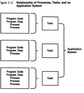
environment. Multiprogramming is supported at three levels: application systems, tasks, and processes. (See figure 1-1.)
o
Any number of application systems can coexist, each in its own memory partition. An application system is a collection of one or more tasks that access a common set of files and implement a single application.o
Any number of tasks (that is, executable programs) can be loaded into the memory of a partition and beindependently executed.
1-2 System Description
Figure 1-1 Relationship of Processes, Tasks, and an Application System
Program Code Program Data
Process Process
Program Code Program Data
Process
Program Code Program Data
Process Process Process
Event-Driven Priority Scheduling
Application System
To meet the need for high performance, the operating system kernel provides efficient event-driven priority scheduling.
System Description 1·3
Interprocess Communication
The kernel's IPC primitives, such as Request and Wait (or Check) are the primary building blocks for synchronizing process execution and transmitting information between processes.
Inter-CPU Communication (ICC)
The ICC facility, which is an extension of IPC, provides for communication between CPUs among the different
processor boards on the XE520.
If the requested system service is on the same XE520
processor board as the client process, the kernel uses IPC. If, however, the service is on a different processor board, the kernel uses ICC. ICC passes request and response messages between processor boards.
The XE520 is compatible with the workstations at the request level. Whether your program runs on an XE520 or a workstation, it can access system services in the same way (either by using the request procedural interface or by calling the kernel primitives).
Messages and Exchanges
When a process needs to send a message to another
process, it sends the address of its message to an exchange. Sending only the address, instead of the actual message, reduces system overhead. At the exchange, the first process can either wait for a response to its message from the second process or poll for a response. If it waits for a response, its execution is suspended until the response occurs; this is how the execution of different processes is synchronized. If the first process polls for a response, it resumes execution of the code which sent the message until a response occurs.
1·4 System Description
All processes share a finite pool of exchanges. The termination of a process automatically deallocates its exchanges. A process that continues to work but has no further use for an exchange should relinquish it.
System Service Processes
BTOS includes system service processes which manage various classes of system resources, such as files and memory. These processes receive requests for their services from other processes through IPC, and they are scheduled for execution in the same manner as application processes. A system service process is the only software element that accesses a particular resource, and the interface to a system service process through IPC is formalized.
Local Resource Sharing Networks (Clusters)
The cluster configuration that executes in the XE520 processors that run XEBTOS is similar to that of the BTOS workstations. The XE520 provides services to processes running on workstations such as file management, queue management, 3270 terminal emulator, and database management. Services such as video and keyboard management are performed at the workstations.
Intercluster communications in the XE520 are handled by Cluster Processors (CPs) in the XE520 enclosures.
Workstations are connected to CPs with high-speed RS-422 channels.
Overlays
System Description 1·5
When the overlay program begins execution, the resident code is loaded into memory, where it remains for the duration of the program's execution. When a call is made to a procedure in one of the overlays, the Virtual Code management facility reads that overlay into memory into an area of memory called the overlay zone so that the program can continue execution.
The Virtual Code management facility keeps as many overlays as possible in memory at once. When another overlay that would exceed the available space is called into memory, the Virtual Code management facility uses a least-recently-used (LRU) algorithm to determine which currently resident overlay to discard.
XEBTOS supports the segment swapping implementation of virtual memory, allowing overlaid run files to execute on every processor board of the XE520.
Refer to your BTOS II Language Development
Programming Guide for more information on overlays.
File Management System
The file management system provides a hierarchical organization of disk file by node, volume, directory, and file. Volumes are automatically recognized when placed on line. A file can have a 50-character file name, a 12
character password, and a file protection. You can
dynamically expand or contract a file without limit as long as it fits on one disk. You can protect the file by a volume directory, or file password, depending on the level number you assign t~ a file. You can control concurrent file access by read (shared) and modify (exclusive access) modes. While providing convenience and security, the file system management also provides the full throughput capability of the disk hardware. This includes reading or writing any 512-byte sector of any open file with one disk access, . reading or writing up to 65,024 bytes with one disk access, overlapping input/output with process execution, and optimizing disk arm scheduling.
1·6 System Description
Two File Header Blocks are created for each volume with a parameter that is set when initializing the disk. This defaults to creating the secondary volume structures. The duplication of critical volume control structures protects the integrity of disk file data against hardware
malfunction. You can recover a file that has been backed up by using the Executive MRESTORE command, if either of the File Header Blocks is valid.
Bros
Versions
In workstation BTOS, memory can be divided into "more than two partitions, each with its own application system, with all the application systems executing simultaneously.
XEBTOS distinguishes between system and application partitions but not between primary and secondary partitions.
System services can be installed only when a single non-system partition exists.
In the XE520 system, there is a tailored version of BTOS on each processor. Each version can be customized to meet the needs of an individual installation. This is discussed in detail in the BTOS II Customizer Programming Guide.
General Structure of BTOS
The five basic components of the BTOS operating system are:
o the kernel
o system service processes o system common procedures
o
object module procedures o device and interrupt handlersSystem Description 1·7
A process, the basic element of computation that competes for access to the processor, consists of the following: o the address of the next instruction to execute on behalf
of this process
o a copy of the data to be loaded into the processor registers before control is returned to this process o a stack
o a default response
When you add a system service process, you assign one of 255 priorities to each process so that BTOS can schedule the process's execution appropriately.
The .kernel's IPe primitives are the primary building blocks for synchronizing process execution and transmitting information between processes.
System service processes are standard processes that manage system resources. These are scheduled for execution in the same way as application processes. The five major categories of system services are:
o task management o network management
o
device management o memory managementA system service can be accessed directly by using the Request and Wait primitives, or indirectly, by using a procedure call from a high-level language. Accessing a system service directly allows an increased degree of concurrence between multiple I/O operations and computation.
1-8 System Description
Object module procedures are supplied as part of an object module file or library. They are not part of BTOS itself. Most application systems require only a subset, not a full set, of these procedures. An example of an object module procedure is the Sequential Access Method (SAM).
BTOS device handlers and interrupt handlers are accessed indirectly through the convenient interfaces of the system service processes.
Section 2
2-1B10S Concepts for the XE520
This section briefly describes BTOS concepts developed for the XE520 environment, concepts that pertain to the routing of information between processors.
Before reading this material, you should be- familiar with BTOS process management. If not, see the discussions on interprocess and interstation communications fn the
BTOS II System Reference Manual.
Inter-CPU Communications
The Inter-CPU Communications (ICC) facility is an upward-compatible extension of the Interprocess Communications (IPC) facility. ICC enables a process on one processor to obtain a service provided by a process on another processor.
When a client process on a particular processor requests a system service, a request block with all the necessary information is constructed. If the requested service resides on a different processor, the request block is queued at the ICC Server exchange on the first processor. The ICC Server converts the request block into a message which is
transmitted via the system bus to the ICC Server on the processor where the requested service resides.
The ICC Server on the second processor then converts the message back into a request block. A CPU Description Table (CDT) on the second processor is used to locate the exchange of the system service that is to perform the requested service, and the request block is queued there.
The response to the request follows a similar route from the second processor to the first processor and undergoes similar transformations. All processors have ICC Servers and CDTs for interboard communications.
2-2 BTOS Concepts for the XE520
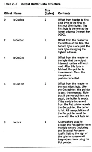
Slot Number
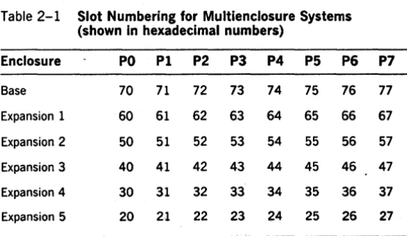
The slot number is the eight-bit binary number that uniquely identifies.a particular processor board in an XE520 system. Processor slot numbers range from a high of hex 77 to a low of hex 20. The slot number is used by certain XEBTOS routines to identify a particular processor and by the hardware to accomplish interboard addressing. Table 2-1 shows slot number assignments for
multienclosure systems.
You can use the GetProclnfo and the GetSlotlnfo operations to retrieve such hardware information and. thereby,
explicitly control ICC routing. You would use these
operations if using one of the XE520 routing types defined in section 3 is not sufficient.
Doorbell Interrupt
Each XE520 processor can send an interrupt, called a doorbell interrupt, to any other board in the system. During initialization, a doorbell interrupt awakens a processor that has just been loaded with that processor's version of BTOS. During ICC communication, a doorbell interrupt alerts the target processor that a request or response needs processing.
Table 2-1 Slot Numbering for Multienclosure Systems (shown in hexadecimal numbers)
Enclosure PO PI P2 P3 P4 P5 P6 P7
Base 70 71 72 73 74 75 76 77
Expansion 1 60 61 62 63 64 65 66 67
Expansion 2 50 51 52 53 54 55 56 57
Expansion 3 40 41 42 43 44 45 46 47
ExpanSion 4 30 31 32 33 34 35 36 37
[image:25.399.34.328.360.530.2]BTOS Concepts for the XE520 2·3
linear Format
XEBTOS describes structures to be read by the processor using a linear pointer. A linear pointer is a 4-byte quantity in which the most significant byte is at the lowest address. A linear pointer is absolute, not segment based.
Like a linear pointer, a linear offset has the most significant byte at the lowest address; however, it is a two-byte quantity. The byte ordering is opposite to the 80x86 convention, which puts the most significant byte at the highest address. Linear offsets are used in XE520 BTOS to describe structures that must be read by both
80x86-based processors. A linear offset within a structure is always taken to be the offset relative to the base
structure.
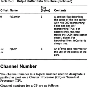
CPU Description Table
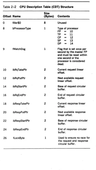
Each XE520 processor contains a CPU Description Table (COT). You can obtain the address of the CDT by calling GetpStructure with a structCode value of 27. The table descri bes the processor to other processors, contains the offsets of the circular buffers used by other processors to send ICC requests and responses, and contains some
2-4 BTOS Concepts for the XE520 Table 2-2 CPU Description Table (COT) Structure
Size
Offset Name (Bytes) Contents
0 filler$O 8 Unused
8 bProcessorType 1 Type of processor
FP 10
TP 11
CP 12
SP 13
DP 14
9 fWatchDog 1 Flag that is set once per second by the master FP and· must be reset within one second or the processor is considered dead.
10 ibRqTakeptr 2 Current request linear offset.
12 ibRqPutptr 2 Next available request linear offset.
14 ibRqStartPtr 2 Base of request circular buffer.
16 ibRqEndptr 2 End of request circular buffer.
18 ibRespTakeptr 2 Current response linear offset.
20 ibRespPutptr 2 Next available response linear offset.
22 ibRespStartptr 2 Base of response circular buffer.
24 ibRespEndptr 2 End of response circular buffer.
[image:27.398.30.348.32.592.2]eTOS Concepts for the XE520 2·5 Table 2-2 CPU Description Table (CDT) Structure (continued)
Size
Offset Name (Bytes) Contents
27 blnitErrorStat 1 If initialization detects an error, the code is placed here.
28 bMemorySize 1 Memory size in kB/128. 29 bBootStruct$FF 1 Signature, value - hex
OFF
30 bBootStruct$O 1 Signature, value - hexO. 31 bBootStruct$A6 1 Signature, value - hex
OA6.
32 bBootCommand 1 Allowable values:
fRunning 0
fBootMe 1
fDumpThenBoot 2
fDumpThenError 3
fF ailed Diagnostics Hex OFO fRunningDiagnostics Hex OF1
33 bMasterFp 1 Master FP slot number
34 fOslnitialized 1 Hex OFF when OS has initialized.
35 fFilier 5
40 rgbFPXlate 8 Array of FP slot numbers. 48 rgBusConfig 240 Array of slot
number/processor types.
288 filler 100 Reserved for future
expansion.
2·6 BTOS Concepts for the XE520 Table 2-2 CPU Description Table (CDT) Structure (continued)
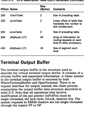
Offset Name 390 sTermTable 392 oLineTable
394 sLineTable 396 oRqRoute (17)
430 sRqRoute (17)
Size
(Bytes) Contents 2
2
2 34
34
Size of preceding table. Linear offset of table that translates line number to slot number/port. Size of preceding table. Array of information for routing requests on each level to other processors. Size of segment each level.
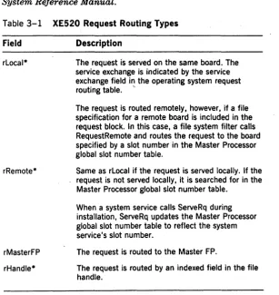
Terminal Output Buffer
The terminal output buffer is the structure used to
describe the virtual terminal output device. It consists of a circular buffer and associated information. A linear pointer to the terminal output buffer is returned by both
WhereTerminalBuffer and OpenTerminal. There is no request interface for output; instead, the client process manipulates the output buffer data structure described in table 2-3. Note that all operations that involve
[image:29.396.40.351.56.440.2]BTOS Concepts for the XE520 2·7
Table 2-3 Output Buffer Data Structure Size
Offset Name (bytes) Contents
0 10OutTop 2 Offset from header to first data byte in the first in, first out (fifo) buffer. The first byte is the one at the lowest address (nearest hex
0000).
2 10OutBot 2 Offset from the header to
the bottom of the fifo. The bottom byte is one past the data byte occupying the highest address.
4 100utGet 2 Offset from the header to
the byte that the output interrupt routine will fetch next. After this byte is fetched, this pointer is incremented. Thus, the discipline is
post-incremented.
6 100utPut 2 Offset from the header to the next client byte. Like the Get pointer, this pointer is post-incremented. Note that if the two pointers are equal, the buffer is empty. If the module increment from the Put pointer equals the Get pointer, the buffer is full. All manipulations of the Put pointer must be done with the lock byte set.
a
foLock 1 A semaphore used to [image:30.397.57.364.45.552.2]2·8 BIOS Concepts for the XE520
Table 2-3 Output Buffer Data Structure (continued)
Offset Name 9
10-17
foCarrier
rgbAP
Channel Number
Size
(bytes) Contents
1
8
A boolean flag describing the sense of the line carrier with hex 000 representing False and hex OFF representing True. For dataset lines, this flag tracks the OCD (data carrier detect) signal. For
hardwired lines, foCarrier is always true.
An 8":'byte area reserved for the use of the clients of the port.
The channel number is a logical number used to designate a particular port on a Cluster Processor (CP) or Terminal Processor (TP).
Channel numbers for a CP are as follows:
Device
8274A 8274B 8251
,
Backpanel Label
Channell
Channel 2
[image:31.399.37.334.51.344.2]Bros Concepts for the XE520 2·9
Channel numbers for a TP are as follows:
Device Backpanel Label
8274#IA Channell
8274#IB Channel 2
8274#2A Channel 3
8274#2B Channel 4
8251#2 Channel 5
8251#1 Channel 6
8251#4 Channel 7
8251#3 ChannelS
8251#6 Channel 9
Section 3
3·1Inter-CPU Communication
The Inter-CPU Communication (ICC) facility provides for communication between CPUs among the different
processor boards on the XE520. ICC is an extension of Inter-Process communication (IPC).
The XE520 is compatible with the workstations at the request level. Messages passed between a client and a system service on the same processor board use IPC. The kernel routes the request to the system service exchange; the system service performs its function and responds to the client's exchange, acknowledging service completion. Requests routed locally on a single XE520 processor board also use IPC.
When a client requests a system service, the kernel examines its request routing table to determine, for example,
o if the request block is correctly formed
o to which system service the request is to be sent
These actions are taken in the case of ICC or IPC. However, the destination to which the request is sent determines if the request is handled as a normal IPC message or if it is to be routed by ICC.
ICC involves interboard routing or the passing of the request and the response message between processor boards. To accomplish this, ICC uses
o processor boards identified by slot numbers o XE520 routing type information in the operating
system's request routing table
o an ICC Server Agent on each processor board, which issues requests on behalf of a client on a different processor board
o communication between processors over a high-speed bus
3·2 Inter-CPU Communication
o Y -blocks and Z-blocks for storing copies of request blocks
o a request ring buffer and a response ring buffer in a CPU Description Table (COT) on each processor board o a doorbell interrupt
Processor board slot numbers, linear pointers and linear offsets, and doorbell interrupts are discussed in section 2.
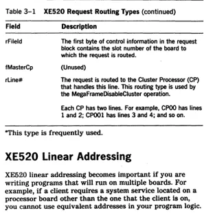
XE520 Routing
Types
Table 3-1 describes each of the XE520 routing types used to define requests on the XE520. If you are writing a system service for the XE520, you will need to include an XE520 routing type in your system service request definition(s). For more information, refer to the BTOS II
System Reference Manual.
Table 3-1 XE520 Request Routing Types
Field Description
rLocal* The request is served on the same board. The service exchange is indicated by the service exchange field in the operating system request routing table. ,.
rRemote*
rMasterFP
rHandle*
The request is routed remotely, however, if a file specification for a remote board is included in the request block. In this case, a file system filter calls RequestRemote and routes the request to the board specified by a slot number in the Master Processor global slot number table.
Same as rLocal if the request is served locally. If the request is not served locally, it is searched for in the Master Processor global slot number table.
When a system service calls ServeRq during installation, ServeRq updates the Master Processor global slot number table to reflect the system service's slot number.
The request is routed to the Master FP.
[image:35.398.34.341.246.570.2]Inter-CPU Communication 3·3 Table 3-1 XE520 Request Routing Types (continued)
Field Description
rFileld The first byte of control information in the request block contains the slot number of the board to which the request is routed.
fMasterCp (Unused)
rLine# The request is routed to the Cluster Processor (CP) that handles this line. This routing type is used by the MegaFrameDisableCluster operation.
Each CP has two lines. For example, CPOO has lines 1 and 2; CPOOI has lines 3 and 4; and so on.
*This type is frequently used.
XE520 Linear Addressing
XE520 linear addressing becomes important if you are writing programs that will run on multiple boards. For example, if a client requires a system service located on a processor board other than the one that the client is on, you cannot use equivalent addresses in your program logic.
Blocks
Blocks are areas of memory allocated for ICC and for cluster communication. Y -blocks and Z-blocks are used for holding ICC messages. A Z-block is used if the message can fit into a small number of bytes; otherwise, a Y -block is used. The size and number of these blocks is determined at system initialization.
Interboard Routing
[image:36.401.69.367.50.359.2]3·4 Inter-CPU Communication Sending Requests
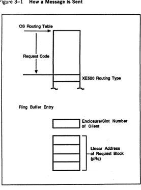
In figure 3-1, a client calls a Request located at the address referenced by the pointer (pRg). The kernel uses the request code (Rq) as an index into the routing table to determine the XE520 routing type. The routing type tells the kernel where to route the request.
How A Message Is Sent
Sending a message is summarized in figure 3-1.
Local Routing?
If request routing indicates that the request is to be served locally and a local server exists, ICC is not used. The request is routed using the normal procedures of IPC.
In figure 3-1, the pointer (pRq), when referencing a request served locally is a logical memory address.
Remote XE520 Processor Routing
If request routing indicates that the request is to be served off board (for example, on a different XE520 processor), ICC is used to send the request.
To send the request, the kernel
1 Enters the client's return address into the CDT request ring buffer on the receiving XE520 processor.
The ring buffer entry consists of 5 bytes that describe the client's return address: 1 byte defines the client board's enclosure and slot number; 4 bytes define the client's request block linear address.
2 Sends a doorbell interrupt to the receiving board.
Sending Responses
Figure 3-1 also shows sending responses.
I nter-CPU Communication
Figure 3-1 How a Message is Sent
OS Routing Table
----~
...
----ReQUTCodO
1 -_ _ _ -1 XE520 Routing Type
Ring Buffer Entry
I
Enclosure/Slot Number.... _ _ _ .... of Client
Unear Address of Request Block (pRq)
To return the remotely response, the kernel takes the following actions:
3·5
1 copies the pb/cb response buffers and a status code to the client's request block memory on the client's board
[image:38.397.72.349.59.432.2]3·6 Inter-CPU Communication
3 places the client's return address in the CDT response ring buffer on the client's board
4 sends a doorbell interrupt to the client's XE520 processor
How
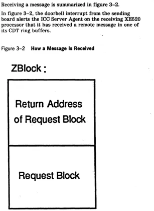
A Message Is Received
Receiving a message is summarized in figure 3-2.
In figure 3-2, the doorbell interrupt from the sending board alerts the ICC Server Agent on the receiving XE520 processor that it has received a remote message in one of its CDT ring buffers.
Figure 3-2 How a Message Is Received
ZBlock:
Return Address
of Request Block
[image:39.399.35.343.147.566.2]Inter-CPU Communication 3·7
The ICC Server Agent examines the ring buffer entry to see if it is a request or a response.
Request?
If the ring buffer entry is a request, the ICC Server Agent
1 Calculates the size of the request by examining the size of the client's request block memory. The ICC Server Agent uses the size to reserve a Z-block (or a Y -block) in the receiving XE520 processor's memory.
2 Copies the request block contents and the client's return address into the reserved Z-block.
3 Calls Request, providing the memory address of the Z-block.
In figure 3-2, Request(pZblock) ·repeats the sending requests procedure in figure 3-1.
The kernel on the receiving board routes the request to the specified service exchange. The message is processed using IPC.
Response?
If the ring buffer entry is a response, the ICC Server Agent calls the Respond primitive (pRq) to alert the kernel on the receiving board to route the response back to the client's local response exchange.
Sending and Receiving Messages
Figure 3-3 shows the interaction of client A on a Cluster Processor (CP) board and system service B on a File Processor (FP) board.
In figure 3-3, client A on the CP board requests (AI) a service provided by system service B on the FP board. The kernel on the CP board places the request block return address in the FP board's CDT request ring buffer and. rings the FP's doorbell.
The ICC Server Agent on the FP board copies the request block contents to a Z-block (or Y -block) in the FP
3·8 Inter-CPU Communication
Figure 3-3 Interaction of Client and System Service Using ICC
service B's service exchange, satisfying system service B's Wait (B2). System service B processes the request and responds (B3).
The kernel on the FP board acts on the Respond (B3) by copying the response back to client A's request block, placing an entry in the CP's CDT response ring buffer, and ringing the CP's doorbell.
The ICC Server Agent on the CP board examines the
response ring buffer and calls Respond (B3'). The kernel on the CP board sends Respond (B3') to client A's response exchange, satisfying the client's Wait (A3).
[image:41.402.39.325.89.284.2]Inter-CPU Communication 3·9
Operations
The ICC operations are described below. These operations are not available to BTOS workstations. (Refer to section 5 for a complete description of each operation.)
GetProcInfo returns the name of the processor on which the caller is running.
GetSlotInfo determines the slot numbers of other processors in the XE520.
RemoteBoot causes another dormant processor to be bootstrapped with a specified System Image.
Section
4
4-1Requests Enhanced in XEBTOS
XE520 processor boards and workstations execute most of the same BTOS II standard software run files, and the XE520 and workstations support a single version of CTOS.lib. For more information, refer to the XE500 BTOS
Administration Guide.
In addition, most of the XEBTOS requests have the same names and functions as their workstation counterparts and are compatible at the request block level. This section lists those requests which have been enhanced to make use of the XE520 hardware.
General Differences
The general differences between XEBTOS and workstation BTOS II are described in the following subsections.
Alternate Request Procedural Interface
With XEBTOS, you can use an alternate request procedural interface to issue requests with other than the default user number. This eliminates the requirement for you to
manually construct request blocks. You invoke this feature by prefixing the name of an operation with "alt" and supplying the desired user number as the first parameter to the procedure. For example, to issue a Close File request with user number 5 and file handle fh, you make the calling s~quence AltCloseFile (5, fh).
Mode Parameters
4·2 Requests Enhanced In XEBTOS
Mode peek allows read access to a file without preventing a different user from modifying the file. Mode peek opens a file in the same way mode modify opens a file. The
operating system puts existing mode peek handles into a state where subsequent operations return error 235. Then it allows mode modify to open the file. Mode peek is useful with files like the Executive Message file, which you may want to update but find constantly opened.
Programmable Interval Timer
The XE520 programmable interval timer runs at a frequency of 19.5 KHz (providing a 51.3 msec resolution) as it does on workstations. You may have to alter your applications to run them under the 51.3 msec resolution. Refer to the BTOS II Customizer Programming Guide.
Direct Printing
XEBTOS does not support direct printing.
Using the Video Control Block
XEBTOS does not maintain the video control block (VCB). The system common pointer which pointed to the VCB in workstation BTOS now points to the CPU description table (COT). Therefore, programs that make direct use of the video control block must be converted before they can run under XEBTOS. For more information on the COT, refer to section 2.
Using Certain SysConfigBlk Fields
Requests Enhanced in XEBTOS 4·3
Using VAM and VDM Operations
The XE520 supports a subset of the Video Access Method (V AM) operations only and one Video Display Method (VDM) operation only. Supported V AM operations include PosFrameCursor, PutFrameAttrs, and ScrollFrame; the supported VDM operation is ResetFrame.
Operations within the V AM subset and the operation within VDM are restricted to provide the functionality of a dumb terminal and do not cause any operation to take place. In addition, PutFrameChars, a VDM operation, outputs characters on the screen but ignores the specified screen coordinates.
Using the Cluster Status Utility
The Cluster Status utility reports cluster errors seen by workstations. Cluster Status utility polling and response to polling occur at interrupt level, and termination requests are sent as a single transaction.
Line 0 is invalid when running the workstation Cluster Status utility from a workstation that is clustered to an XE520. This is the only restriction.
Byte-stream Video
In XEBTOS, byte-stream escape sequences (beginning with hex OFF) are ignored. The output model is that of an RS232-C serial terminal. Standard byte-stream sequences are supported.
Communications Byte Streams
Communications byte streams support the 8251 chip on both the Cluster Processor and Terminal Processor processor boards. The support of the chips allows you to access port C on the CP board and ports E through J of the TP board in the same way as other RS232-C
4·4 Requests Enhanced In XEBTOS
The interpretation of n as in [Comm]n depends on whether it is executed on a Terminal Processor or on a Cluster Processor. n has to be running in the processor with the port that is being addressed. Table 4-1 illustrates the different interpretations.
Table 4-1 Processor Interpretation of n
Terminal Cluster
n Channel Processor Processor
A 1 8274#1A 8274A
8 2 8274#18 82748
C 3 8274#2A 8251
D 4 8274#28
E 5 8251#2
F 6 8251#1
G 7 8251#4
H 8 8251#3
9 8251#6
J 10 8251#5
Specific Request Difference
Changes in specific requests that have been enhanced to make use of the XE520 hardware are listed in this
subsection. Refer to the BTOS II System Reference Manual
for more information.
AllocExch
[image:47.399.37.324.117.360.2]Requests Enhanced in XEBTOS 4·5
RequestDirect
The RequestDirect kernel primitive allows direct interboard message passing. Each XE520 processor board has a unique exchange value; the value is returned whenever you call the AllocExch service. RequestDirect works with the Genetic Print System (GPS) to install multiple printer drivers. The GPS routing switch uses RequestDirect to issue work to drivers installed on different boards.
SetTrapHandler
The SetTrapHandler operation does not create trap handlers that are part of a partition's context; therefore, trap handlers are not switched when processes run in a different context. Instead, the trap handlers are global to the processor board on which SetTrapHandler executes. Because of this, only one program per processor board can use software traps. The software trap handler's primary client is the Pascal floating-point run-time library.
QueryDCB
The QueryDCB service copies the Device Control Block (DCB) of the specified device to the specified memory area. The information is truncated if it cannot fit in the memory area. There is a DCB for each physical device. For example, the DCB for a disk includes the number of tracks per disk and the number of sectors per track. The DCB points to a chain of I/O blocks.
QueryDCB needs no password. To prevent security violations, a string of zeros is returned in the DCB device (sbPassword) field.
4·6 Requests Enhanced in XEBTOS
Table 4-2 DCB Changes in XEBTOS Size
Offset Field (Bytes) Description
65 gaplength 1 WdlOlO/Wd2010
intersector gap parameter.
66 writePrecompt 1 Cylinder after which write precomposition is used.
67 stepRate 1 WdlOlO/Wd2010 step rate
value.
76 fEccFormat 1 True if disk formatted in ECC mode.
77 reserved 1
78 fOnLine 1 True if drive is on line (used in polling).
79 flnhibitEcc 1 For SMD drives.
GetVhb
The GetVhb service copies the Volume Horne Block (VHB) of the specified device to the specified memory area. If the specified area is not large enough to hold the requested information, XEBTOS truncates the information.
GetVhb requires no password. To prevent security violations, zeros are returned in the vol Password field of theVHB.
[image:49.396.33.341.48.386.2]Requests Enhanced in XEBTOS
Table 4-3 VHB Changes In XEBTOS
Offset Field (Bytes)
247 SeekStepRate 1
248 gapsize 1
249 WritePreCompCyl 1
250 devType 1
251 reserved 5
ServeRQ
4·7
Description
Wdl0l0jWd2010 step rate value.
Wdl0l0/Wd2010 intersector gap parameter.
Cylinder after which write precomposition is used.
00 == fixed disk 81 == EPI tape
The ServeRQ service is the part of a dynamically installed system service process that serves a specified request code. Future requests containing this request code are queued at a specified exchange.
ServeRQ functions the same way on XEBTOS as on workstation BTOS. The XE520 enhancement involves the visibility of the request. If the routing type of the request is rRemote, the server is globally visible to all processors in the XE520 system. Otherwise, only the pr.ocessor on which ServeRQ is issued can see the server.
SetCommlSR and ResetCommlSR
[image:50.396.69.355.64.347.2]4·8 Requests Enhanced in XEBTOS
Allowable values for the parameter iLine, which identifies the SIO channel, are extended on a Cluster Processor as follows:
o 0 refers to Channel 1
o 1 refers to Channel 2 (8274 Channels B and A, respectively).
Note: SetCommlSR and ResetCommlSR are now available for backwards compatibility only. InitCommLine has been
implemented as a replacement for SetCommlSR. ResetCommLine has been implemented as a replacement for ResetCommlSR.
DisableCluster
The DisableCluster service allows an application system on the master terminal to disable polling of the cluster
terminals after a specified time period. This service is also used to resume polling of the cluster terminals.
Section 5
XE520 Procedures and Services
This section describes procedures and services that have been added to BTOS for the XE520 environment. These procedures and services fall into five categories.
Return Information:
GetProclnfo returns information about the processor on which the application is running.
5·1
GetSlotlnfo returns the slot numbers of the processors in a particular category.
ExpandSpec returns an expanded file specification that includes information from the caller's path.
Handle terminal input/output:
OpenTerminal prepares a terminal for I/O.
DrainTerminalOutput ensures that a terminal output buffer is empty. Usually·used prior to a SetTerminal operation.
SetTerminal ascertains or changes the characteristics, both hardware and software, of a terminal.
ReadTerminal reads one or more characters from a terminal.
WhereTerminalBuffer locates a terminal buffer for output.
CloseTerminal closes an open terminal.
Route interprocessor communications:
RemoteBoot loads a designated processor with an operating system and starts the execution of the image.
RequestRemote sends a request to a particular processor.
ReadRemote receives standard read requests mapped by the ICC if remote Direct Memory Access (DMA) is required.
Route comunications:
5-2 XE520 Procedures and Services
ResetCommISR purges the Communications Interrupt Services Routines (CISRs) previously established for the specified communications channel.
InitCommLine allocates a communications channel (serial port) to the user and specifies how interrupts from the channel are to be serviced.
ResetCommLine resets the comm line Handle half-inch magnetic tape:
CloseTape removes a user's exclusive access to a specified tape drive, thereby making the tape drive available to another user. For half-inch tape, CloseTape rewinds the tape. The tape is not rewound for QIC tape.
Open Tape gives a user exclusive access to a tape drive.
PurgeTapeUser aborts all outstanding tape requests from a user and removes the user's exclusive access to all tape drives.
ReadTapeRecords reads the next n fixed length records from tape into a user buffer.
TapeStatns returns tape status information and clears outstanding error conditions.
TapeOperation sends non-data transfer commands to the tape drive.
WriteTapeRecords writes one or more fixed length records.
XE520 Procedures and Services 5·3
GetProclnfo
Description
The GetProcInfo service fills a caller-supplied array with the name of the processor on which the caller is running. The format of the processor name is ttnn.
tt is the board type-one of the following strings: FP, CP, SP, DP, or TP.
nn is the two-digit relative slot number (in decimal) of the board.
Procedural Interface
GetProclnfo (pMySlotRet, pTypeRet, pNumberRet, pbNameRet, cbNameMax, pbNameLenRet): ercType
pMySlotRet is a pointer to a byte where the slot number of this board is placed. Refer to section 2 for a further description of how slot numbers are sequenced.
pbTypeRet is a pointer to a byte where the processor type is placed. Processor types conform to the hardware type codes that are used in the Processor Type field of the CDT.
pbNumberRet is a pointer to a byte where the ordinal number of the processor is placed. To determine a
processor's ordinal number, view the base enclosure from the rear and count processors of the same type from left to right (the slot numbers decrease). If the system has a second enclosure (an expansion enclosure to the left of the main enclosure), continue counting processors from left to right. Continue the count through any further enclosures in the same manner.
pbNameRet and cbNameMax is a (pointer, length) pair that defines the location and size of the array to receive the name of the processor.
pbNameLenRet is a pointer to a byte where the length of the name of the processor is placed.
5-4 XE520 Procedures and Services GetProclnfo Examples
If the GetProclnfo service is called in the second Cluster Processor, the results would be:
MySlotRet - hex 75 (an arbitrary value for this example) TypeRet - hex 011
NumberRet - hex 01 N ameRet - CPO 1
If this routine is called in the third File Processor, the results would be:
MySlotRet - hex 51 (an arbitrary value for this example) TypeRet - hex 010
XE520 Procedures and Services
GetSlotl nfo
Description
GetSlotinfo determines the slot numbers of other processors in the system.
5-5
The GetSlotinfo primitive fills a caller-supplied array with the slot numbers of all of the processors of a specified type, and it returns the number of processors of the specified type. GetSlotinfo may be used to find the slot number of the master File Processor.
If the caller supplies an array too small to hold all of the slot numbers, as many entries as possible are placed in the array, then status code 211 is returned. This status code tells you that the buffer size is invalid. The number of processors is correctly returned.
Procedural Interface
GetSlotinfo (bCode, pbSlotArrayRet, cbSlotArrayRet, psProcessorCountRet): ercType
where bCode takes on one of the following values:
bCode Processor Type
1 File Processor
2 Terminal Processor
3 CI uster Processor
4 Application Processor
5 Storage Processor (not part of a DP)
6 Disk Processor
5·6 XE520 Procedures and Services
Other values of bCode are reserved for future expansion.
pbSlotArrayRet and cbSlotArrayRet is a (pointer, length) pair that defines the location and size of the area to
receive the slot numbers of the processors specified by bCode.
psProcessorCountRet is a pointer to a word in which the number of processors of the type specified in bCode will be placed.
Request Block
GetSlotlnfo is a system common procedure with the following error codes:
211 - ercBadBufferSize
XE520 Procedures and Services 5·1
ExpandSpec
The ExpandSpec service expands an incomplete file specification to a full specification that contains the node, volume, directory, file and password, if required, of the caller. ExpandSpec accepts the incomplete specification values from pbFilespec and pbPassword. It completes the specification by obtaining information from the caller's default path.
ExpandSpec can only expand specifications for users at the workstation where the request was issued. The returned specification is in canonical form. For example, the volume name returned will always contain the name assigned to the volume when it was initialized rather than [Sys) or [Scr). For unmounted or uninitialized volumes, the volume name field will be returned as the device name. In the case of the <$
>
directories, the expanded directory name will always be returned.Procedural Interface
ExpandSpec (pbFileSpec, cbFileSpec, pbPassword, cbPassword, pSpecRet, sSpecMax, specType): ercType
pbFilespec and cbFilespec describe the partial specification to be expanded.
pbPassword and cbPas8word describe the password, if any.
pSpecRet and sSpecMax describe the expanded file specification format returned.
5·8 XE520 Procedures and Services
Request Block
Offset Field Size Contents
0 sCntInfo 1 6
1 RtCode 1 0
2 nReqPbCb 1 2
3 nRespPbCb 1 1
4 userNum 2
6 exchResp 2
8 ercRet 2
10 rqCode 2 253
12 specType 2
14 reserved 2
18 pbFileSpec 4
22 cbFileSpec 2
24 pbPassword 4
28 cbPassword 2
32 pSpecRet 4