ISSN Online: 2153-1293 ISSN Print: 2153-1285
DOI: 10.4236/cs.2017.812021 Dec. 28, 2017 285 Circuits and Systems
Voltage-Mode Third-Order Quadrature
Sinusoidal Oscillator Using VDBAs
Kanhaiya Lal Pushkar
Department of Electronics and Communication Engineering, Maharaja Agrasen Institute of Technology, Rohini, India
Abstract
This paper presents a third-order quadrature sinusoidal oscillator (TOQSO) using two voltage differencing buffered amplifiers (VDBAs), three capacitors and a resistor. The new topology provides two quadrature voltage outputs. The condition of oscillation (CO) and frequency of oscillation (FO) are elec-tronically independently controllable by the separate transconductance of the VDBAs. The workability of the proposed TOQSO is confirmed by SPICE (Version 16.5) simulation using Taiwan semiconductor manufacturing com-pany (TSMC) 0.18 µm process parameters.
Keywords
Voltage Differencing Buffered Amplifier, Third-Order Quadrature Sinusoidal Oscillator, Voltage-Mode
1. Introduction
An oscillator is a very important basic building block, which is frequently used in electrical and electronics engineering applications. Among several types of sinusoidal oscillators, the quadrature oscillators are widely used because they can offer sinusoidal signals with 90˚ phase difference, for example, in telecommuni-cations for quadrature mixers and SSB generators [1], for measurement purpos-es in vector generators and selective voltmeters [2]. Because of these applications number of QSOs has been realized employing different active building blocks in the open literature [3]-[8]. Different variety of active building blocks (ABBs) have been introduced in [9], VDBA is one of them. Since its introduction in [9], VDBA has been used in many signal processing and signal generation applica-tions. Two biquad filters have been realized in [10] using two VDBAs and two capacitors and a resistor. In [11] VDBA based three lossless and lossy inductance How to cite this paper: Pushkar, K.L.
(2017) Voltage-Mode Third-Order Quadra-ture Sinusoidal Oscillator Using VDBAs. Circuits and Systems, 8, 285-292.
https://doi.org/10.4236/cs.2017.812021
Received: December 4, 2017 Accepted: December 25, 2017 Published: December 28, 2017
Copyright © 2017 by author and Scientific Research Publishing Inc. This work is licensed under the Creative Commons Attribution International License (CC BY 4.0).
http://creativecommons.org/licenses/by/4.0/
DOI: 10.4236/cs.2017.812021 286 Circuits and Systems simulators have been proposed employing two or three passive components. Single VDBA based multifunction filter configuration was proposed in [12] us-ing five or six passive components. Quadrature oscillator employus-ing three VDBAs, three capacitors and two resistors was proposed in [13]. The objective of this communication is to present a new voltage-mode TOQSO structure em-ploying two VDBAs, three capacitors and a resistor which is based on a non-inverting VM low pass biquadratic filter and inverting VM integrator in a closed loop. The workability of the proposed configuration is verified by SPICE simulation using 0.18 µm TSMC technology transistor parameters.
2. Proposed Methodology
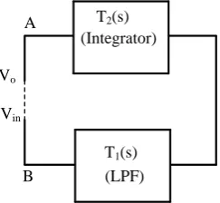
Figure 1 shows the basic methodology to obtain a TOQSO by cascading a second-order non-inverting low pass filter with an inverting integrator or by cascading an inverting second-order low pass filter with non-inverting integra-tor. The open loop voltage gain of Figure 1 can be expressed as:
( ) ( )
(
3)
1 2 2
0 1 2
o
in
V a
T s T s
V s a s a s a
−
= =
+ +
(1)
where 1
( )
20 1 2
1 T s
a s a s a
=
+ + and
( )
3 2
a T s
s
= −
or 1
( )
20 1 2
1 T s
a s a s a
= −
+ + and
( )
3 2
a T s
s
=
To produced sustained oscillations, Vo = Vin and hence the characteristic
equ-ation can be denoted as
3 2
0 1 2 3 0
a s +a s +a s+a = (2)
The CO and FO can be deduced from Equation (2) as follows:
0 3 1 2
CO :a a =a a (3)
3 2
0
1 0
FO : a a
a a
ω = = (4)
3. The Proposed Third-Order Quadrature Oscillator Configuration
The symbolic notation and equivalent model of the VDBA are shown in Figure 2(a) and Figure 2(b) respectively [9]. Using standard notations, the voltage-(LPF) (Integrator)
Vin
Vo
A
B
T2(s)
[image:2.595.322.444.591.703.2]T1(s)
DOI: 10.4236/cs.2017.812021 287 Circuits and Systems VDBA
p
n
v
wv
zw
z
v
pv
n Ip In Iw Izv
pv
nV
wV
z -1I
z(a) (b) Figure 2. (a) Symbolic notation (b) equivalent model of VDBA.
VDBA1 p n w z VDBA2 R0
C1 C2
p n z w C3 Vo1 Vo2
[image:3.595.221.530.78.138.2]Non-inverting LPF Inverting Integrator
Figure 3. New proposed third-order quadrature sinusoidal oscillator.
current relations of VDBA can be described by the following matrix. 0 0 0 0
0 0 0 0 0 0
0 0 0
p p
n n
z m m z
w w
I V
I V
I g g V
V β I
= − (5)
[image:3.595.246.495.170.331.2] [image:3.595.305.436.385.444.2]where β is a non-ideal voltage gain of VDBA. The value of β in an ideal VDBA is unity and gm is the transconductance of the VDBA.
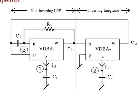
Figure 3 shows the proposed new TOQSO with independent electronic con-trol of both FO and CO.
The expression for characteristic equation (CE) of the circuit of Figure 3 is given by (Detailed explanation of Equation (6) with the help of Figure A1 is given in Appendix):
3 2 1 2 2 1 1 2
1 2 3
0 0 0
CE : C C C gm g gm m 0
s C C C s s
R R R
+ + + =
(6)
The condition of oscillation and the frequency of oscillation can be given as
2 2 0
3
CO : m C
g R
C
≤ (7)
1 0
0 1 3
FO : gm R C C
ω =
(8)
The relationship between Vo1 and Vo2 can be obtained as:
2 2
90
1 2 2
2
ej
o
o m m
V j C C
V g g
ω ω −
−
DOI: 10.4236/cs.2017.812021 288 Circuits and Systems From Equation (9) it is evident that Vo1 and Vo2 are in quadrature.
4. Sensitivity Analysis
The sensitivity is an important performance criterion of any circuit structure. The sensitivities of ω0 with respect to active and passive elements are given by
0 0 0 0
1 3 0 1
1 1
,
2 m 2
C C R g
Sω =Sω =Sω = − Sω =
(10)
It may be easily observed from Equation (10) that all sensitivities are lower than unity in magnitude, for the proposed third-order quadrature oscillator. It ensures that the sensitivity performance is good.
5. Simulation Results
To confirm theoretical analysis, the proposed TOQSO was simulated using CMOS VDBA (as shown in Figure 4). The CMOS VDBA is implemented using 0.18 µm TSMC real transistor models [14]. The aspect ratios of transistors used in Figure 4 are shown in Table 1. The passive elements were selected as C1 = 1.0
nF and C2 = 1.0 nF, and R0 = 1.66 kΩ. The transconductances of VDBAs were
controlled by the bias currents. SPICE generated output waveforms indicating transient and steady state responses of circuit of Figure 3 are shown in Figure 5 and Figure 6 respectively. The results of TOQSO in Figure 5 and Figure 6 show more accuracy than the second order ones. These results, thus, shows the valid-ity of the proposed configuration. Figure 7 shows the output spectrum of circuit
M5
M1 M2
M12 M6
VSS VDD
M3 M4
M8 M9
M13
M10 M11
Vbias1
Vp Vn
Vbias2
M16 M15
M14
M7
Vz
Vw
Figure 4. CMOS implementation of VDBA [10], VDD = VSS = 0.9 V.
Table 1. The aspect ratios of transistors used in Figure 4.
Transistor W (µm) L (µm)
M1-M4, M10, M11, M15, M16 7 0.35
M5, M6 21 0.7
M7, M8 7 0.7
M9 3.5 0.7
DOI: 10.4236/cs.2017.812021 289 Circuits and Systems Figure 5. Transient response of proposed third-order quadrature sinusoidal oscillator.
Figure 6. Study state response of proposed third-order quadrature sinusoidal oscillator.
Figure 7. Frequancy response of proposed third-order quadrature sinusoidal oscillator.
shown in Figure 3; whereas the total harmonic distortion (THD) for both the outputs, Vo1 and Vo2 are found to be 2.55% and 0.48% respectively. The THD at
output Vo2 is very small. Figure 8 shows the Lissajous pattern for the circuit of
Figure 3. The circles are shown in the Figure 8, indicates that two signals are at 90˚ phase difference.
0 0.2 0.4 0.6 0.8 1 1.2 1.4 1.6 1.8 2
x 10-3 -0.3
-0.2 -0.1 0 0.1 0.2 0.3
Time (s)
V
ol
tage
(
V
)
1.95 1.96 1.97 1.98 1.99 2
x 10-3 -0.3
-0.2 -0.1 0 0.1 0.2 0.3
Time (s)
V
ol
tage
(
V
)
Vo2 Vo1
104 105 106 107
10-6 10-4 10-2 100
Frequency (Hz)
V
ol
tage
(
V
)
Freq. of osc. = 81.05kHz THD for :
Vo1 = 2.55% Vo2 = 0.48%
[image:5.595.222.526.451.615.2]DOI: 10.4236/cs.2017.812021 290 Circuits and Systems Figure 8. Frequancy response of proposed third-order quadrature sinusoidal oscillator.
6. Conclusion
A new voltage-mode third order quadrature sinusoidal oscillator with indepen-dent electronic control of both CO and FO using two VDBAs, three capacitors and a resistor is introduced. The CO can be electronically controlled by tran-scoductance (gm2) of VDBA2 without affecting FO. FO can also be electronically
adjusted by transcoductance (gm1) of VDBA1 without affecting CO. The
pro-posed TOQSO offers low sensitivities. The circuit exhibits good high frequency performance. One can design TOQSO with single VDBA. Workability of the proposed configuration is verified by SPICE simulation using 0.18 µm TSMC technology.
References
[1] Horng, J.W., Hou, C.L., Chang, C.M., Chung, W.Y., Tang, H.W. and Wen, Y.H. (2005) Quadrature Oscillators Using CCIIs. International Journal of Electronics, 92, 21-31. https://doi.org/10.1080/00207210412331332899
[2] Gibson, J.D. (1997) The Communication Handbook. CRC Press, Boca Raton, FL, USA, 1997.
[3] Tangsrirat, W. and Surakampontorn, W. (2090) Single-Resistance-Controlled Qua-drature Oscillator and Universal Biquad Filter Using CFOAs. AEU - International Journal of Electronics and Communications, 63, 1080-1086.
https://doi.org/10.1016/j.aeue.2008.08.006
[4] Horng, J.W. (2002) Current Differencing Buffered Amplifiers Based Single Resis-tance Controlled Quadrature Oscillator Employing Grounded Capacitors. IEICE Transactions on Fundamental of Electronics, Communications and Computer Sciences, E85-A, 1416-1419.
[5] Ozcan, S., Toker, A., Acar, C., Kuntman, H. and Cicekoglu, O. (2000) Single Resis-tance-Controlled Sinusoidal Oscillators Employing Current Differencing Buffered Amplifier. Microelectronics Journal, 31, 169-174.
https://doi.org/10.1016/S0026-2692(99)00113-5
[6] Prommee, P. and Dejhan, K. (2002) An Integrable Electronic-Controlled Quadra-ture Sinusoidal Oscillator Using CMOS Operational Transconductance Amplifier. International Journal of Electronics, 89, 365-379. https://doi.org/10.1080/713810385
[7] Rodriguez-Vazquez, A., Linares-Barranco, B. Huertas, J. L. and Sanchez-Sinencio,
-0.25 -0.2 -0.15 -0.1 -0.05 0 0.05 0.1 0.15 0.2 0.25
-0.2 -0.1 0 0.1 0.2
Voltage (V), Vo1
V
ol
tage
(
V
), V
DOI: 10.4236/cs.2017.812021 291 Circuits and Systems E. (1990) On the Design of Voltage-Controlled Sinusoidal Oscillators Using OTAs. IEEE Transactions on Circuits and Systems, 37, 198-211.
https://doi.org/10.1109/31.45712
[8] Holzel, R. (1993) A Simple Wide-Band Sine Wave Quadrature Oscillator. IEEE Transactions on Instrumentation and Measurement, 42, 758-760.
https://doi.org/10.1109/19.231604
[9] Biolek, D. Senani, R., Biolkova, V. and Kolka, Z., (2008) Active Elements for Analog Signal Processing: Classification, Review, and New Proposals. Radioengineering, 17, 15-32.
[10] Kacar, F. Yeil, A. and Noori, A. (2012) New CMOS Realization of Voltage Diffe-rencing Buffered Amplifier and Its Biquad Filter Applications. Radioengineering, 21, 333-379.
[11] Firat Kacar, A. Y. (2016) VDBA-Based Lossless and Lossy Inductance Simulators and Its Filter Applications. Signal Processing and Communication Application Conference (SIU) 24th 2016,Zonguldak, Turkey, 16-19 May 2016.
[12] Gupta, P. and Pandey R. (2017) Single VDBA Based Multifunction Filter. Interna-tional Journal of Control Theory and Applications, 10, 651-661.
[13] Malhotra, C., Ahalawat, V. V., Kumar, V. Pandey, R. and Pandey, N. (2016) Voltage Differencing Buffered Amplifier Based Quadrature Oscillator. 1st International
Conference on Power Electronics, Intelligent Control and Energy Systems (ICPEICES-2016),Delhi, India, 4-6 July 2016.
https://doi.org/10.1109/ICPEICES.2016.7853457
[14] Minaei, S and Yuce, E. (2010) Novel Voltage-Mode All-Pass Filter Based on Using DVCCs. Circuits System and Signal Processing, 29, 391-402.
DOI: 10.4236/cs.2017.812021 292 Circuits and Systems
Appendix
VDBA1
p
n w
z
VDBA2
R0
C1 C2
p n
z w C3
Vo1
Vo2
Non-inverting LPF Inverting Integrator
iz1 iz2
1
2
[image:8.595.219.499.78.260.2]3
Figure A1. New proposed third-order quadrature sinusoidal oscillator.
KCL at node 1:
1 1 1 1
1
(
)
1z m p n z
i
=
g
v
−
v
=
v sC
1
(
1 1)
1 1m p n z
g
v
−
v
=
v sC
(a)KCL at node 2:
2 2 2
2
(0
)
2z m n z
i
=
g
−
v
=
v sC
2 1 2 2
,
m z z
g v
v sC
−
=
(b)
KCL at node 3:
1 3 2 3 1
0 0
1
1
(
)
n z z
v
sC
v sC
v
R
R
+
=
+
(c)