/
I
OEM MANUAL
Model 3350
Model 6650
Model 15450
FOURTEEN INCH
PRiAM
Fourteen-Irlch Winchester Disc Drives
OEM MANUAL
JANUARY, 1984
© 1984, PRIAM CORPORATION
SHEET AND REVISION TABLE
EC 2052
SHT
i
i i
iii
1
2
3
4
5
6
REV
B
B
B
B
B
B
B
B
B
SHT
7
8
9
10
11
12
13
14
15
REV
B
B
B
B
B
B
B
B
B
SHT
16
17
18
19
20
21
22
23
24
REV
B
B
B
B
B
B
B
B
B
SHT
25
:26
27
28
29
30
31
32
33
REV
B
B
B
B
B
B
B
B
B
SHT
34
:35
36
37
38
39
40
41
42
REV
B
B
B
B
B
B
B
B
B
--SHT
43
44
45
46
47
48
49
50
TABLE OF CONTENTS
Section '" Page
TABLE OF CONTENTS ... i
LIST OF FIGURES ... ii
LIST OF TABLES ... iii
1. GENEHAL INFORMATION ... 1
1.1 Introduction ... 1
1.2 Options ... 2
1.2.1 Interface Types ... 2
1.2.2 Interface Cables and Terminators ... 2
1.2.3 Power Supplies ... 2
1.2.4 Mounting Hardware ... 2
2. SPECIFICATIONS SUMMARy ... 3
2.1 General Specifications ... .' ... 3
2.2 Reliability Specifications ... 4
2.2.1 Defects ... ·4
2.2.2 Preventive Mai ntenance . . . .. 4
2.3 Power Requi rements ... 4
2.4 Mounting/Weight Specifications ... 4
2.4.1 Weight ... 4
2.4.2 Mounting ... 4
3. RECEIVING, INSTALLATION AND SHiPPiNG ... 6
3.1 Introduction ... 6
3.2 Unpackaging the Drive ... 6
3.2.1 Shipping Damage Inspection ... 6
3.2.2 Removing Drive From Shipping Container 6 3.2.3 Inspection Procedures ... 7
3.3 Handling Procedures ... 7
3.3.1 Shock and Vibration Precautions ... 7
3.3.2 Spindle and Head Locks ... 7
3.3.3 Drive Handling Guidelines ... 8
3.4 Shipping Requirements ... 8
3.4.1 Spindle and Carriage Locks ... 8
3.4.2 Shipping a Stand-Alone Unit ... 8
3.4.3 Shipping Drive Mounted in an Enclosure. 8 3.5 Functional Testing ... 8
4 PRIAM INTERFACE OPERATION ... 9
4.1 Mounting ... 9
4.2 Power Supply Setup ... 9
4.3 Switch Settings ... 9
4.4 Jumper Settings ... 13
Section Page 4.5 Cabling Requirements ... 13
4.5.1 Interface Connectors ... 13
4.5.2 Interface Cable Characteristics ... 15
4.6 Signal Functional Requirements ... 15
4.6.1 Interface Signal Descriptions ... 16
4.6.2 Serial Data Transfer Control Signals .... 19
4.6.3 User-Accessible, Registers ... 20
4.6.4 Commands ... 21
4.6.5 Register Bit Definitions ... 22
4.6.6 Interface Timing ... 22
4.7 Track Format Considerations ... 29
4.7.1 Write/Read Timing Constraints ... 29
4.7.2 Control Timing Constraints ... 29
4.7.3 Suggested Datll Format ... 29
4.8 System Grounding ... 31
5. SMD INTERFACE OPERATION ... 33
5.1 Mounting ... 33
5.2 AC Power Set-Up ... 33
5.3 Switch Settings ... 33
5.4 Jumper Settings ... 34
5.5 Cabling Requirements ... 37
5.5.1 Interface Cables and Connectors ... 37
5.5.2 DC Power Connector ... 38
5.5.3 AC Power Connector ... 38
5.5.4 Remote Panel Connector ... 38
5.5.5 Interface Cable Characteristics ... 39
5.6 Signal Functional Requirements ... 39
5.6.1 Interface Signal Descriptions ... 40
5.6.2 Interface DC Characteristics ... 43
5.6.3 Interface Timing ... 45
5.7 Track Format Considerations ... 50
5.7.1 Write/Read Timing Constraints ... 50
5.7.2 Control Timing Constraints ... 50
5.7.3 Suggested Data Format ... 51
5.8 System Grounding ... 52
APPENDIX A RETURN OF PRIAM DRIVES FOR SERVICING ... 53
APPENDIX B ENVIRONMENTAL SPECIFICA-TIONS FOR DRIVES PACKED IN PRIAM SHIPPING CONTAINER ... 53
LIST OF FIGURES
Page
1-1 DISKOS 3350, 6650, and 15450 ... . 2-1 PRIAM 14-lnch Disc Drive Dimensions
and Mounting ... " ... 5
3-1 Slhipping Package ... 6
3-2 Spindle and Head Carriage Locks ... 7
4-1 Jumper and DIP Switch Locations for Assembly 200113 " ... 10
4-2 Jumper and DIP Switch Locations for Assembly 200173 " ... 10
4-3 Jumper Locations for PCB Assembly 200248-01/02 ... "... 11
4-4 Jumper Locations for PCB Assembly 200248-21/22 ... "... 11
4-5 Jumper Definitions and Locations and DIP Switch Locations for PCB Assembly 200208/200398 ... 12
4-6 Jumper Locations for PCB Assembly 200213 ... " ... 12
4-7 Jumper Locations for PCB Assembly 200514-1/200515-1 ... 13
4-8 Typical Test Panel Schematic ... 15
4-9 PRIAM Interface Connector ... 15
4-10 DBUS Transceiver ... 16
4-11 Single End Line Receiver Gated by DRIVE SELECT. " ... 17
4-12 Single End Line Receiver ... 17
4-13 Single End Line Driver ... 18
4-14 Differential Line Drivers and Receivers ... 19
4-15 Register Load Timing ... 23
4-16 Register Read Timing ... 23
4-17 Reset Timing ... 24
4-18 INDEX and SECTOR MARK Timing ... 24
4-19 WHITE DATA and VVRITE CLOCK Timing 25 ii Figure Page 4-20 READ DATA and READ CLOCK Timing .. 26
4-21 Record Writing Timing ... 27
4-22 Record Reading Timing ... 27
4-23 Read and Write Transitions During Gaps. 28 4-24 Format Definition ... " ... 30
4-25 Recommended System Grounding ... 31
5-1 DIP Switch and Jumper Locations for PCB Assembly 200088 ... 34
5-2 DIP Switch and Jumper Locations for PCB Assembly 200148-01/02 ... 35
5-3 DIP Switch and Jumper Locations for PCB Assembly 200218/200263 ... 35
5-4 Jumper Locations for PCB Assembly 200403-01/02 ... 36
5-5 Jumper Locations for PCB Assembly 200514-1/200515-1 ... 36
5-6 Jumper Locations for PCB Assembly 200213 ... 37
5-7 Typical Test Panel Schematic . . . .. 38
5-8 Typical Read/Write Data and Clock Transmitter and Receiver ... 43
5-9 Control Line Transmitter ... 44
5-10 Control Line Receiver ... 45
5-11 Tag and Bus Timing ... 46
5-12 Typical Read Timing ... 47
5-13 Typical Read Control Timing ... 47
5-14 Typical Write Control Timing ... 48
5-15 Index and Sector Mark Timing ... 48
5-16 Drive Select Timing ... 49
5-17 NRZ Data and Read Clock Timing ... 49
5-18 Recommended Sector Format ... 51
5-19 Recommended System Grounding ... 52
308002
LIST OF TABLES
Table Page
2-1 Functional Specifications ... 3
2-2 Environmental Specifications ... 3
2-3 -DC Power Requirements ... 4
3-1 Winchester Disk Drive Handling Guidelines (Unpacked) ... 8
4-1 DIP Switch Selection ... 9
4-2 Jumper Selection ... 14
4-3 DC Power Connector ... 14
4-4 AC Power Connector ... 14
4-5 Remote Panel Connector ... 14
4-6 Remote Write Protect Function ... 15
4-7 DBUS Transceiver DC Charactl3ristics .... 16
4-8 Single End Line Receiver Gated by DR IVE SELECTED Characteristics ... 17
4-9 Single End Line Receiver DC Characteristics ... 17
4-10 Single End Line Driver DC Characteristics 18 4-11 Differential Line Receiver DC Charcteristics ... 19
4-12 Differential Line Driver DC Characteristics 19 4-13 Head Selection ... 19
4-14 Drive Fault Conditions ... 20
4-15 Register Selection ... 21
4-16 Command Code Summary ... 21
4-17 Drive ID Assignments ... " ... 22
4-18 Status Register Bit Definitions" ... 22
Table Page 4-19 Target and Current Cylinder Address Register Bit Definitions ... 22
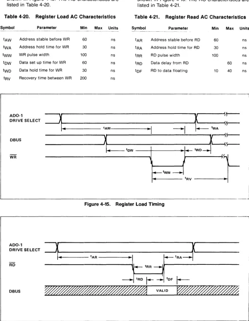
4-20 Register Load AC Characteristics ... 23
4-21 Register Read AC Characteristics ... 23
4-22 Reset AC Characteristics ... 24
4-23 INDEX and SECTOR MARK AC Characteristics ... 24
4-24 WRITE DATA and WRITE CLOCK AC Characteristics ... " 25 4-25 READ DATA and READ CLOCK AC Characteristics ... 25
4-26 Record Writing Control AC Characteristics26 4-27 Record Readi ng Control AC Characteristics .... ' ... " 26 4-28 Sector Format Examples Using ECC ... 30
5-1 DIP Switch Selection ... 33
5-2 Jumper Selection ... 34
5-3 Jumper Definitions for PCB Assembly 200218/200263 ... 37
5-4 DC Power Connector ... 38
5-5 AC Power Connector ... 38
5-6 Remote Panel Connector ... 38
5-7 Remote Write Protect Function ... 38
5-8 Tag Bus I/O Interface ("A" Cable) ... 39
5-9 Tag Bus Decode ("A" Cable) ... 39
5-10 "B" Cable Interface ... 40
Figure 1·1. DISKOS 3350, 6650 and 15450
1. GENERAL INFORMATION
1.1 Introduction. The DISKOS :3350, 6650 and 15450 use advanced Winchester and micro-processor technologies to provide users with low-cost disc drives having high capacity, fast access, and long-term reliability. Linear motor voice coil positioners with track following servos enable the DISKOS 3350, 6650 and 15450 to position Win-chester type heads quickly and precisely. These low-force heads assure high data reliability.
Advanced '14-inch Winchester-technology discs are driven by an outer-rotor, brush less DC motor. The head positioner coil and carriage, heads and discs are enclosed in a sealed, contamination-resistant chamber to assure high reliability.
1
Two heads serve each disc surface, with one head and data band dedicated to servo information for fully servoed track following, head positioning and write timing. One disc recorded at 480 tracks per inch with three data bands is used in the DIS-KOS 3350 to provide a capacity of 34 megabytes of unformatted data. In the DISKOS 6650, one disc is recorded at 960 tracks per inch with three data bands to provide a capacity of 68 megabytes of unformatted data. In the DISKOS 15450, two discs are recorded at 960 tracks per inch with seven data bands to provide a capacity of 158 megabytes of unformatted data.
Microprocessors are used in the disc drive elec-tronics to provide interface flexibility and to moni-tor drive operation. For example, they control
power up and down sequencing, and a self-test program checks drive performance during each power-up sequence. Any malfunction detected by tlhese tests will prevent drive start-up, reducing tlhe chance of loss o'f data or damage to the drive.
PRIAM disc drives are constructed in a modular fashion so that defective assemblies can be easily replaced. This greatly reduces down time due to servicing. The six assemblies are:
Head Disc Assembly Main PCB Assembly
Motor Control PCB Assembly Power Supply Module (Optional) Photocell Ass€!mbly
Frame Assembly
The Head Disc Assembly (HDA) is a sealed enclo-sure. It contains the drive spindle assembly, drive motor, voice coil motor, head carriage assembly, read/write heads, magnetic discs, and air filter assembly.
The Main PCB Assembly contains all the circuitr~
associated with read/write control, command exe-cution, information transfers through the user interface, processing servo signals from the servo read head, and controlling the position of the head carriage.
The Motor Control PCB Assembly contains the circuitry associated with driving the spindle motor. This circuitry receives an ON/OFF com-mand from the main PCB, and spindle rotation feedback from the Photocell Assembly.
If the PRIAM power supply option is chosen, the power supply is mounted within the Frame As-sembly. The PRIAM power supply can operate from 50 or 60 HZ, with input voltage (selectable) of 1100, 120, 220, or 240 V /JIC.
The Photocell Assembly contains the photO-de-tectors which sense the DC Motor position. This information is used to control the electrical com-mutating required for brush less DC motors.
The Frame Assembly is constructed to accommo-date all optional assemblies of the disc drive. Its open steel rod and sheet metal design provides im-proved air circulation and makes the drive lighter, lower in cost and easiE~r to install.
"1.2 Options
"1.2.1 Interface Types. The PRIAM 14-inch disc drives are available with a variety of
inter-face options. All interinter-faces available from PRIAM include on-board data separation.
The standard PRIAM interface is designed for low cost and efficient use with micro-processor-based systems. Up to four drives may be daisy-chained when this interface is used. Tlhe PRIAM interface provides a basic a-bit bidirectional bus, which may be used with the popular a-bit and 16-bit mi-croprocessors. It also provides bit-serial N RZ data exchange. No elaborate handshaking protocols are required. The PRIAM interface is built into the disc drive's main PCB. A 50-conductor flat ribbon cable is used between the PHIAM interface and the host system.
The SMD interface permits a PRIAM 14-inch drive to be used with existing Storage Module Drive (SMD) controllers. The SMD interface is embedded in the main PCB assembly and can be connected directly to an SMD controller. The line drivers and line receivers in the SMD interface are matched to those of typical SMD controllers. There are two interface cables between the host system and the drive interface - a 60-conductor twisted-pair flat cable ("A" cable) and a 26-conductor flat ribbon cable (" B"cable).
An ANSI interface adapter is also available. Char-acteristics of the ANSI interface include variable and fixed sector sizes,data transfer rates up to 10 megabits per second, and radial attention and se-lect capability. Up to eight dlrives may be daisy-chained on a single 50-conductor flat ribbon cable.
1.2.2 Interface Cables and 'Terminators. I/O ca-bles are available from PRIAM for con-necting daisy-chained drives to one another.
Terminators are available for I/O Signal lines to minimize reflections and to ensure maximum data integrity. One terminator is r1equired for a single drive or for the last drive in a daisy chain. Each drive is shipped with a terminator installed.
1.2.3 Power Supplies. PRIAM's optional power supply allows PRIAM elisc drives to operate from 100, 120,220, and 240 VAC, 50 or 60 Hz power. The optional power supply iis delivered already mounted within the drive frame. No extra space or interconnection is required.
1.2.4 Mounting Hardware. Optional sl ides are available from PRIAM .. These slides allow easy access to drives mounjted in standard 19" racks and cabinets.
2. SPECIFICATIONS SUMMARY
2.1 General Specifications. Table 2.1 provides functional specifications for the PRIAM 14-inch series of disc drives. Table 2.2 provides operational and non-operational environmental specifications for the disc drives.
Table 2·1. Functional Specifications
Capacity Unformatted
Per Drive (bytes) Per R/W Head (bytes) Per Track (bytes) Formatted
(128 bytes/sector; 111 sectors/track) Per Drive (bytes) Per R/W Head (bytes) Per Track (bytes) Formatted
(256 bytes/sector; 65 sectors/track) Per Drive (bytes) Per R/W Head (bytes) Per Track (bytes) Formatted
(512 bytes/sector; 35 sectors/track) Per Drive (bytes) Per R/W Head (bytes) Per Track (bytes) Formatted
(1024 bytes/ sector 18 sectors/track)
DISKOS 3350 DISKOS 6650 DISKOS 15450
33,929,280 67,798,080 158,195,520 11,309,760 22,599,360 22,599,360 20,160 20,160 20,160
23,912,064 47,781,504 7,970,688 15,92'7,168 14,208 14,208
111,490,176 15,927,168 14,208
28,005,120 55,960,320 130,574,080 9,335,040 18,65~3,440 18,653,440 16,640 16,640 16,640
30,159,360 60,264,960 140,618,240 10,053,120 20,088,320 20,088,320 17,920 17,920 17,920
Per Drive (bytes) 31,021,056 61,986,816 Per R/W Head (bytes) 10,340,352 20,662,272 Per Track (bytes) 18,432 18,432
144,635,904 20,662,272 18,432 Transfer Rate
(Mbytes/sec) Rotational Latency
(Average) Access Times (max)
Track to Track Average Longest Seek
Disc Surfaces Data Heads Cylinders
Track Density (TPI) Nominal RPM
1.04 1.04
9.7 msec 9.7 msec
10 msec 10 msec 48 msec 48 msec 86 msec 86 msec
2 3 561 480 3100 2 3 1121 960 3100 1.04
9.7 msec
12 msec 48 msec 86 msec 4 7 1121 960 3100 3
Table 2·1. Functional Specifications (cont'd.)
DISKOS DISKOS DISKOS 3350 6650 15450
Recording Characteristics:
Maximum Density (BPI) 6430 6430 6430 Recording Code MFM MFM MFM
Start Time (max) 45 sec 45 sec 90 sec Stop Time (max)
(With Dynamic
Brake) 45 sec 45 sec 90 sec
Table 2-2. Environmental Specifications ¥¥
Equipment Operational Equipment Non-Operational Ambient 15°C/hr max rate of change 30° C/hr max rate of change Temperature 10° to 40° C' +5° to 60° C
Relative Humidity
Altitude
Vibration
Shock
(50° to 104°F) (41° to 140°F)
8% to 80% without con-densation.
From 1000 feet below sea
8% to 90% without con-densation.
From 1000 feet below sea level to 12,000 feet above sea level to 40,000 feet above sea level. Derate maximum tem- level.
perature linearly to 35°C from 7,000 to 12,000 feet. Drives are capable of sustained exposure to vi-brations as specified dur-ing normal operation and exhibit no non-recover-able error conditions.
0.3 g's from 100 to 300 Hz.
0.0003 inch 0 to peak from 60 to 100 Hz.
0.1 g's from 14 to 60 Hz
0.005 inch 0 to peak from 2 to 14 Hz
Drives are capable of sustained exposure to vi-brations as specified dur-ing normal operation and exhibit no non-recover-able error conditions.
The shocks will be a half sine wave with peak level of 1 g and have a dura-tion of 11 msec.
Drives are capable of exposure to vibration as specified while non-opera-tiona I with mechanical locks set and exhibit no damage or operational performance degradation.
2.0 g's from 45 to 300 Hz.
0.010 inch 0 to peak from 2 to 45 Hz
Drives are capable of exposure to shock as specified while non-opera-tiona I with mechanical locks set and exhibit no damage or operational performance degradation.
The shocks will be a half sine wave with peak level of 25 g's and have a dura-tion of 11 msec.
• 100 CFM air flow should be supplied to the drive end to end to maintain temperature within these limits.
.. Refer to Appendix B for Environmental Specifications of drive packaged in PRIAM shipping container or equivalent shipping container.
308002
2.2 Reliability Specifications
MTBF: 10,000 power on hours.
MTTR: 30 minutes.
Component Life: 5 years
Acoustic Noise Level: 60 db at 1 meter
Error Rates:
Seek Errors < 1 per 106 seeks
Soft Read Errors < 1 per 1010 bits transferred Hard Read Errors < 1 per 1013 bits transferred
2.2.1 Defects. Defects are hard errors found in the disc during disc drive manufacture. Defects are identified by PRIAM to the user when disc drives are delivered. A defect is a media flaw which is 3
bytes or less in length. Any track containing more than 3 defects is considered "bad" by PRIAM. Each bad track is considered one defect for purposes of the specification. The maximum number of defects and bad tracks for each of the DISKOS 14-inch prod-ucts is shown below.
3350 6650 15450
Defects (max.) Bad Tracks (max.)
40 15
100
35
230 82 (Cylinder zero is guaranteed to be defect free)
2.2.2 Preventive MaintE!nance. No preventive mai n-tenance is required.
~~.3 Power Requirements.
AC Power (Optional)
PRIAM's optional power supply provides all of the specified DC requirements. The power supply requires a minimum of 425 watts at 47·63 Hz and one of the following voltages:
1 00 VA C ± 10 % 120 V A C ± 10 % 220 VAC ± 10% 240 VAC ± 100
/0
The power consumption drops to 350 watts max following startup.
DC Power
All PHIAM 14·inch disc drives require power from four DC voltages:
+
24,+
5, - 5, and - 12 volts. DC power is supplied via a 6-pin connector (AMP 1-480270-0 socket and 6 AMP PINS 60617-1, or equivalent).Table 2·3. - DC Power Requirements
CURRENT AMPS
PIN RIPPLE
VOLTAGE TaL. NUMBER MAXIMUM TYPICAL (MV pop MAX)
+24 ±5%
(-15% while starting)
7.0 **
(while starting)
5.5 (seeking)
4.0
(not seeking)
** Peak current may exceed this number for 5ms.
+5 ±5% 4.0 1.5
-5 ±5% 3 2.0 1.0
-12 ±5% 0.7 0.5
GND 8.7
24 volt return 6 7.0
48 (*500)
10 (*100)
10 (*100)
24 (*200)
• Allowed for power systems with + or - 3% tolerance including line and load regulation and ripple frequency components under 1 MHz. Ripple frequency components greater than 1 MHz must be less than 5 MV P·P.
Power Dissipation: 1190 BTU / H maximum (350 walts)
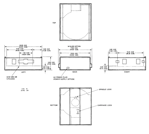
2.4 Mounting/Weight Specifications. Outline drawings of DISKOS 14-inch products are provided in Figure 2-1.
2.4.1 Weight. Weights of PRIAM 14-inch disc drives are shown below:
Basic disc drive (Ibs.) Power Supply Option (Ibs.) Slide Option (Ibs.)
3350 6650 15450
34 18
6
34 18
6
40 18
6
2.4.2 Mounting. The recommended mounting ori-entations are (i) horizontally, with PCB up for cooling, or (ii) vertically, with the power supply side of the rack frame down and positioner motion horizontal. The exact locations of the drives' mount-ing pads are shown in Figure 2-1. All PRIAM 14-inch drives can be mounted in a standard 19-inch rack. PRIAM offers an optional slide mounting kit for use with the 14-inch drive models.
TOP
-r
6.118 '0.03
+ (17.48 .a.08)
-, , ,
"
'--W/SLIOE OPTION
17.56 -0.03
1 _ - - - -(44.6~ '0.08)
-I ..
· f - - - -16.56 -0.03 - - - -...
·1
(42.0$ '0.08)4.68 -0.02
(11.89 '0.05) 14.25 -0.02
1---(36.20
0 0 . 0 5 )-~
.
[b
D
-L~~ _ _ _ • •
---+-2-.2S~.a.02 I
,-===;;;;;==========;;;;;;;;;J(5.72 '0.05).
-t--/
2.25 .a.02
(5.72 -0.05)
C--
---~]
8-32 UNC-2B 5 PLACES
LEFT
x.xx in.
(x.xx)
Figure 2·1.
BACK
AC POWER PLUG (POWER SUPPLY OPTION)
BOTTOM
/ '
/
/
_-../
- , ~ SPINDLE LOCK
~
--q:
I
/ ' , 1
I \ I ( \ I
\ ( I
\, ___ , / : ~CARRIAGE LOCK
---~~
cb
1i
-I
1
:
PRIAM 14·lnch Disc Drive Dimensions and Mounting
5
RIGHT
308002
[image:10.617.65.564.72.521.2]3. RECEIVING, INSTALLATION AND
SHIPPING
3.1 Introduction. This section contains proce-dures for installing all PRIAM 14-inch drives. Included are instructions for unpacking and inspecting, handling guidelines, and shipping instruc:tions.
3.2 Unpackaging thE. Drive.
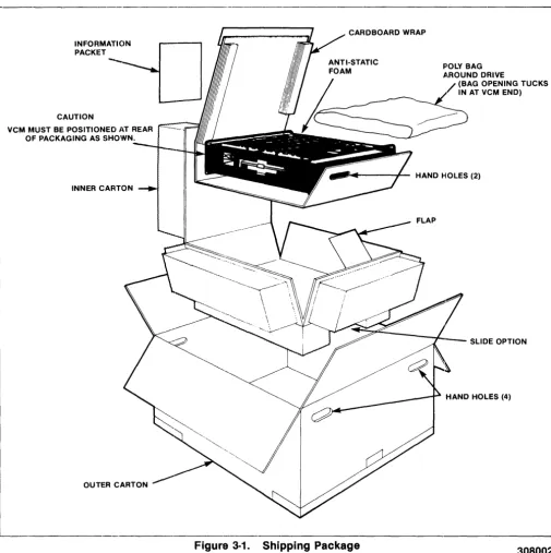
3.2.1 Shipping Damage Inspection. The disc drive is packaued to withstand normal handling in a reusable shipping container.
It
is the c:ustomer's responsibility to notify the carrier if shipping damage should occur to the drive.INFORMATION PACKET
--CAUTION
VCM MUST BE POSITIONED AT REAR OF PACKAGING AS SHOWN.
INNER CARTON
OUTER CARTON
L
When the shipment is received, the shipping con-tainer should be examined for obvious signs of shipping damage. Most insurance adjusters re-quire inspection of the damaged container. Notify the carrier and PRIAM Custorner Service immedi-ately if shipping damage is discovered.
NOTE: When handling the drive while in the ship-ing container, insure that the container remains in the upright position as indicated by the attached labels.
3.2.2 Removing Drive From Shipping Container. The drive shipping container consists of an outer and inner carton. (Sf3e Figure 3-1.) Open
CARDBOARD WRAP
Fl'OLY BAG
~.ROUND DRIVE
(BAG OPENING TUCKS IN AT VCM END)
. . .... - - - - + - HAND HOLES (2)
SLIDE OPTION
HAND HOLES (4)
[image:11.617.58.563.246.752.2]the outer carton by cutting the tape securing the top flaps. Next, cut the tape on the tongue of the inner carton. Fold back the top of the inner carton. Grasp the hand holes at each end of the drive's cardboard wrapping and carefully lift drive out of the inner carton.
CAUTION
The weight of the drive is substantial and if drop-ped can cause severe damage to the Head/Disk Assembly, which will not be covered under warranty.
Place the drive on a clean, flat surface and remove the protective cardboard and polyethylene wrap. Retain the shipping container for any future ship-ments of the drive.
3.2.3 Inspection Procedures. After unpacking the disc drive, inspect it thoroughly for damage hidden by the packagin~J and for loose components or fittings, as follows:
LEVER POSITIONED TOWARDS ~_ DRIVE CASTING-SPINDLE LOCKED
LEVER POSITIONED AWAY FROM DRIVE CASTING-SPINDLE UNLOCKED
SPINDLE LOCK
---.
a. Inspect the interior for shipping damage. b. Examine internally mounted components for
loose or misSing hardware. c. Tighten all loose hardware.
d. Clean the frame interior by removing loose debris.
e. Check that head and spindle locks are secure.
3.3 Handling Procedures
3.3.1 Shock and Vibration Precautions. The drives must be handled in a manner as not to, exceed the Non-Operational Shock and Vibra-tion limits specified in Table 2.2.
3.3.2 Spindle and Head Locks. Both the drive spindle and the head carriage are locked at the factory prior to shipment. After the drive has been positioned for bench testing or installed in the final system, the spindle and head carriage locks must be set in the "Unlock" position to allow normal operation. Both locks are located on the bottom of the H DA (Head Disc Assembly). See Figure 3-2.
0
0
LOCKED POSITIOND
UNLOCKEDD
POSITION CAR R IAGE/HEAD LOCKNOTE: HEADS MUST BE RETRACTED BEFORE LOCK IS OPERATED
I (1) (1) (1) I
L _____________________________________________________
~FigurEI 3·2. Spindle and Head Carriage Locks
7
3.3.3 Drive Handling C3uidelines. Adhere to the steps outlined in Table 3-1 when handling drives.
Table 3-1. Winchester Disk Drive Handling Guidelines (unpacked)
• Always lock spindle/carriage whenever drive is moved. (Do not try to lock while drive is spin-ning.)
• Do not drop drive from any height. Drive should be laid down carefully.
• Carts used for transporting drives should have soft rubber wheels to absorb shock.
• Drive should be stored or transported in a verti-cal position with lon~~ dimension horizontal or flat, top up, and drive motor down. Drive must be on a flat surface. Do not put papers, etc. under drive"
• Only unlock spindle when drive is in normal op-erating attitude.
• Do not apply power when spindle is locked.
• Do not dress or re-position components, wires or cables.
• Do not place drives in vertical position closer than 2-3 inches apart to avoid hitting and break-ing components.
.' Avoid manual rotation of the spindle or move-ment of the carriage. Damage to the disc surface may occur if the heads are moved across a non-rotating disc surface.
.' Do not remove plugs from HDA assembly. This may result in contamination which may affect drive operation. Do not attempt to disassemble HDA.
.' Do not lay objects on top of drive, espeCially metallic objects.
:t4
Shipping Requirements.3.4.1 Spindle and Carriage Locks. Before pack-aging a drive for shipment, it is necessary to secure the spindle and carriage locks. (See Fig-ure 3.2.) A sequence down operation must be per-formed before the drivle can be removed from the system and the locks are engaged. After the dle has come to a complete stop, engage the spin-dle lock to clamp the 'fan blades. Also, move the head carriage lock to tl1e "Locked" position since the heads should be retracted into the landing ,zone by the previous sequence down operation. If
the head lock lever cannot be~ engaged fully Do
Not Force. Instead, return the lever to the unlocked
position, tilt the drive so that the round VCM as-sembly pOints downward and then return the car-riage lock to the locked position.
3.4.2 Shipping A Stand-Alone Unit. After the drive is removed from the system (with the spindle and carriage locks secure), the drive must be packaged to withstand the environmental ex-tremes specified in Table 2-2. Use of the original PRIAM shipping container is recommended. A user designed shipping container may be substi-tuted if it meets or exceeds the PRIAM non-oper-ating environmental specifications.
NOTE: Failure to ship the drive in a proper con-tainer will void its warranty.
Important! Remove slides, brackets, parts of
en-closures and cabhes from the drive before plaCing it in the shipping con-tainer.
3.4.3 Shipping Drive Mount.~d in an Enclosure. When shipping the drivE~ while it is installed in a system, all environmental specifications in Table 2-2 must be adhered to. Vibrations around 50 Hz should be carefully checked when shipping drives in large mainframe systems, as they can cause the drive to resonate! on its protective shock mounts. If the system ()r enclosure cannot be packaged for shipment so that the drives will meet the specifications in Section 2.2, it is recom-mended that the drive(s) be removed from the sys-tem or enclosure prior to shipment and shipped as a stand-alone unit. (See Section 3.4.2.)
3.5 Functional Testing. The following func-tional test is a recommended test for in-coming receiving inspection to insure that the drive is operational and that riO shipping damage . has occurred.
Time Test
1. 1 min. Power up drive and get ROY. 2. 15 sec. Perform max. length seeks. 3. 15 sec. Perform random seeks. 4. * Format, if applicable.
5. 1-3 min. Sequentially write all cylinders and all heads with worst case pattern. (924 ••. , 249 ••• , 492 .•• ) 6. 1-3 min. Sequentially rea.d what was written. 7. 1 min. Random Write and Read.
* Time dependent on size of drive and formatter used.
4. PRIAM INTERFACE OPERAITION
This section provides information for setting up all 14-inch drives having a PRIAM Interface for use in an OEM system. This includes power selection, jumper and switch settings, interface signal defi-nitions and other information to insure proper sys-tem operation.
4.1 Mounting. All PRIAM 14-inch drives can be mounted in a standard 19-inc:h rack. PRIAM offers an optional slide mounting kit for use with the 14-inch drive models. See Figure 2-1 for mount-ing dimensions.
4.2 Power Supply Setup. If a PIRIAM optional power supply is used, check the AC voltage selection circuit board prior to applying power.
This board is adjacent to the AC input plug, and is an integral part of the power supply. To select a voltage, remove the selection circuit board and re-insert it so that the proper AC voltage designation (100, 120, 220, or 240) is visible. Also check the fuse value. A 5-amp fuse is used with 100 or 120 VAC operation, while a 2.5-amp fuse is used with 220 or 240 VAC operation. No modification is re-quired for changing between 60 Hz and 50 Hz power.
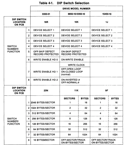
4.3 Switch Settings. The drive address, write protect parameters, and sector size are all switch selectable. The switches are located on the main PCB. Referring to Table 4-1, set the switches according to the desired operating conditions for the applicable Model Drive. See Figures 4-1, 4-2 and 4-5
for the locations of the applicable DIP switches.
Table 4·1. DIP Switch Selection
DRIVE MODEL NUMBER
3350·01 6650·10/3350·10
DIP SWITCH
LOCATION 16R 10K
ON PCB
1 DEVilCE SELECT 1 DEVICE SELECT 1
2 DEVICE SELECT 2 DEVICE SELECT 2
3 DEVICE SELECT 3 DEVICE SELECT 3
SWITCH 4 DEVICE SELECT 4 DEVICE SELECT 4 NUMBER/
FUNCTION 5 OFF·SKIP DEFECT ON·SKIP DEFECT RECORD PROTECTED RECORD PROTECTED
6 WRITE ENABLE HD 0 ON·WRITE ENABLE
WRITE CLOCK
OFF·OPEN LOOP
7 WRITE ENABLE HD 1 ON·CLOSED LOOP (normal)
8 WRITE ENABLE HD 2 ON·INVERTED (21 OFF·NORMAL (21
DIP SWITCH
LOCATION 23N 11K
ON PCB
SECTORS BYTES
1 2048 BYTES/SECTOR 1 16
2 1024 BYTES/SECTOR 2 32
3 512 BYTES/SECTOR 4 64
I
SWITCH 4 256 BYTES/SECTOR 8 128 NUMBER/
FUNCTION 5 128 BYTES/SECTOR 16 256
6 64 BYTES/SECTOR 32 512
7 32 BYTES/SECTOR 64 1024
i
8 16 BYTESISECTOR OFF·SECTOR/TRACK ON·BYTES/SECTOR
9
15450·10
-1J
DEVICE SELECT 1
-_._,-- . -DEVICE SELECT 2
DEVICE SELECT 3
-DEVICE SELECT 4
-9F
I
SECTORS I BYTES
I
1 I 16
+
-2 I I 32
+-_._.
4 I 64 I
1
-8 I 128
I I
16 I 256
I
32 I I 512
+-_ ..
-64 I I 1024 OFF·SECTOR/TRACK ON·BYTES/SECTOR
308002
[image:14.612.106.505.276.742.2]••
W2~
L~
WB: : W9
•
• WlO
: W5
(:]
~~F--ll~l
D
JBJl
,---,
I 7 5 3 1 I
J4 ~==:::
:::=;
I B 6 4 2 I
L _ _ _ _ _ _ J
,---,
I 5 3 1 I
J3 ~=:::J C~
I 6 4 2 I
L ____ -'
Figure 4·1. Jumper and DIP Switch Locations for Assembly PIN 200113
---.---~
E
;l~~I. _~. W14••
W2 W3•
•
5FW6
•••
ABC~~J
Wll W12
••••••
ABC ABC••
W13
ABC
W15 • • •
~~Q
CBA
•••
WB CBA•
W16••
W17
•••
ABC
JB
J1
, - - - l
I 7 5 3 1 I
J4 ~-=--::.::: :::=~
I B 6 4 2 I
L ______ .J r---,
I 5 3 1 I
J3 ~-=-_-::J r~
I 6 4 2:
L _____ .J
Figure 4·2. Jumper and DIP Switch Locations for Assembly PIN 2010173
W19 DO W7 :
~ W1
ABC
W6 • • •
W11 • • •
ABC
W15 W16
• • 11 W12 • • • • • • ABC: ABC CBA
G
WI3 • • • CBA
W13 • •
10K
11K
17M
W17 • • •
ABC
J1
W20 G8
DO W18 LNG RST
Figure 4-3. Jumper Locations for PCB Assembly 200248-01/02
0 W30
~
~
W6
•••
ABCW11 W12 W15 W16
~
••• •••
•
••
•••
J2 J1ABC ABC ABC CBA
~
W21 W8
••• •••
ABC CBA
W19
DO
~
~
W20
DO
W13
DO W18
W17
•••
DOABC LNG RST
Figure 4-4. Jumper Locations for PCB Assembly 200248-21/22
11
308002
~:---.l
~
IN = WRITE PROTECT
~~
F~~
IN = ENABLE LONG RESET
~
W2· ~
•
W3:
l
~
________
6B ______~
IN = SKIP DEFECT RECORD NOT PROTECTED
J4
r--' '-1
I 1 L.J 2 I
: 3 r1 4
I
I 5 I I 6 I
L_.J L_.J
J3
---~---.---~
Figure 4-5. Jumper Definitions and Locations and DIP Switch Locations for PCB Assembly 200208/200398
;~[l
W
Jl
BCA
W5 • • •
W6
•
•
B
W7
••
Figure 4-6. Jumper Locations for PCB Assembly 200213
---.---J1
W30 o
DO W2
[image:18.617.60.569.54.367.2]W4 • •
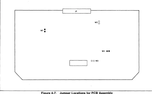
Figure 4-7. Jumper Locations for PCB Assembly 200514-1/200515-1
4.4 Jumper Settings. Jumpers are black con· ductive tabs that can be inserted on board pins to complete a particular circuit. Although most of these are used only at the factory to facili· tate testing, some have user selectable functions. It is important that all jumpers be installed in their proper locations. See Figures 4-1 to 4-6.
Refer to Table 4.2 for jumper position to enable the correct operating conditions for the application.
4.5 Cabling Requirements. All drive signal connections are made via a single 50-pin ribbon cable connector. A second 50-pin connector is available on the main PCB for daisy chaining to another drive or for a terminator for the last drive in the string. Up to four drives may be daisy chained.
A separate connector for DC powE~r is provided. If the optional power supply is installed, then its out-put is connected to this DC power connector and AC power must be supplied to the optional power supply.
An 8 pin DIP socket for remote write protect con-trol~ fault clearing and drive status is also pro-vided on the Main PCB.
13
4.5.1 Interface Connectors. The interface cables and connectors are defined as follows:
1. Interface Connectors
The interface connectors are 50-pin ribbon cable connectors and provide for interface cable and ter-minator connections. The pins are numbered 1 through 50. A recommended mating connector is 3M 3425-0000. The pins are defined in Figure 4-9.
2. DC Power Connector
This connector is used to supply DC power to the drive. It is a 6-pin AMP MATE-N-LOK connec-tor, and the recommended mating connector is an AMP 1-480270-0 socket with AMP 60619-1 pins.
Table 4-2. Jumper Selection
I 3350-10 6650-10 ·15450-10
Mode Jumpe NumbE 'r
!r 200113 120017 3 ,·01
1200248-~
1200248-21200173~0212O0248-021200248-22
200208I
20021:3 1 200514-1 1 200515-1WI W2 W3 W4 W5 Wfi WJ W8 W9 W10 W11 W12 W13 W14 W15 W16 W17 W18 W19 W20 W21 IN IN IN IN IN IN IN IN IN IN X X X X X X X X X X X IN IN IN IN IN
A B
IN
A B
IN IN A B B C IN IN A A A B B B X X X X
1. X = Jumper does not exl 51.
IN X
X X
IN IN
IN X
X X
AB AB
IN X
AB AB
X X
X X
AB AB
BC BC
IN IN
X X
AB AB
AB AB
AB AB
uso
uso
OUT OUT
uso
uso
X BC
2. For -03 (MIS), jumper m ust be Installed. 3. USO = User Selected Op tlon (See Figure 4-3).
Table 4·3. DC POWER CONNECTOR
PIN VOLTAGE
1 Ground
2 +24 VDC
3 -5 VDC
4 -12 VDC
5 +5 VDC
6 Ground (+ 24V
Return)
3. AC Power Connector
IN IN IN IN IN BC IN BC IN IN BC AB IN IN BC BC BC x X x X
This is a 3-pin connl9ctor used to supply AC power to the disc drive! when the PRIAM optional power supply is used. The mating connector is a Belden 5PH-386 or E~quivalent.
Table 4·4 AC POWER CONNECTOR
PIN VOLTAGE
L 100 to 240 VAC (HOT)
E Frame Ground
N 100 to 240 VAC (COM MON)
IN X
uso
IN IN INX X
uso
IN OUT OUTIN IN
uso
X OUT ININ X X X IN IN
X X X BC X X
BC BC X IN X X
IN X X IN X X
BC BC X X X X
X X X NOTE2 X X
X X X X X X
BC BC X X X X
AB AB X X X X
IN IN X X X X
X X X X X X
BC BC X X X X
BC BC X X X X
BC BC X X X X
uso
uso
x x x XOUT OUT X X X X
uso
uso
x x x xX BC X X X X
4. Remote Panel Connector
This is an 8-pin DIP socket connector. It provides limited remote status sensing and control as described in Table 4-5.
Table 4·5 Remote Panel Connector
PIN SIGNAL NAME
1 - WRITE PROTECT
(CONTROL)
2 FAULT RESET (CONTROL)
3 READY~TATU~
4 Ground
5 BUSY (STATUS)
6 DRIVE FAULT (STATUS)
7 Reserved
8 + 5 VDC (POWEf~)
[image:19.617.49.560.63.328.2]Table 4·6. Remote Write ProtEtct Function (Front Panel Switch Write Protects when Closed)
3350-10 6650-10
15450-10
Open Switcih 10K-6 to en-able Remotl3 Write Protect Switch
Remove Jumper W1 to en-able RemotE~ Write Protect Switch
R E : - l : l \OM \ S T
Ft~~LT~
RESET
1--+---1--.
WRITE PROTECT
• LED CURRENT LIMITING RESISTOR
Figure 4-8. Typical Test Panel Schematic
4.5.2 Interface Cable Characteristics
1. Interface Cable
Type:
Impedance: Wire Size:
Propagation Time: Maximum Cable Length:
2. DC Power Cable
Type: Wire Size:
3. AC Power Cable
Type: Power:
Flat Ribbon
10'50hms 28 AWG 1.37 nsec/ft.
25 ft.
6 conductor Vinyl 18 AWG Stranded
SVT Vinyl
1250 wa.tts, 10 amps
4.6 Signal Functional Requirem.!nts. The i nter-face signal names of the PRIAM 14-inch disk drives are listed in Figure 4-9.
Pin Signal Name Line Type
---_._---1 Ground Ground
2 + DBUS 0 Bidirectional/Single 3 + DBUS 1 Bidirectional/Single 4 + DBUS 2 Bidirectional/Single 5 + DBUS 3 Bidirectional/Single 6 + DBUS 4 Bidirectional/Single 7 + DBUS 5 Bidirectional/Single 8 + DBUS 6 Bidirectional/Single 9 + DBUS 7 Bidirectional/Single 10 Ground Ground
11 - READ GATE Received/Single 12 Ground Ground
13 - RESET Received/Single 14 Ground Ground
15 -WRITE GATE Received/Single 16 Ground Ground
17 -RD Received/Single 18 -WR Received/Single 19 +AD 1 Received/Single 20 +AD 0 Received/Single 21 Ground Ground
22 - DRIVE SELECT 1 Received/Single 23 - DRIVE SELECT 2 Received/Single 24 - DRIVE SELECT 3 Received/Single 25 - DRIVE SELECT 4 Received lSi ng Ie 26 Ground Ground 27 Ground Ground
28 +5 VDC (Terminator Power) Diode OR'ed/Single* 29 - HEAD SELECT 4 Received/Single 30 - HEAD SELECT 2 Received/Single 31 - HEAD SELECT 1 Received/Single 32 Ground Ground
33 -INDEX Transmitted/Single 34 Ground Ground
35 - READY Transmitted/Single 36 Ground Ground
37 - SECTOR MARK Transmitted/Single 38 Ground Ground
39 +WRITE DATA ReceivedlDlFF 40 -WRITE DATA ReceivedlDlFF 41 Ground Ground 42 + WRITE CLOCK Received or
Transmitted/DIFF 43 - WRITE CLOCK Received or
Transmitted/DI FF 44 Ground Ground
45 + READ/REFERENCE CLOCK Received or TransmittedlDlFF 46 - READ/REFERENCE CLOCK Received or
TransmittedlDlFF 47 Ground Ground
48 + READ DATA Transmitted/ 01 FF 49 + READ DATA Transmitted/ 01 FF 50 Ground Ground
*Supplied by drive. NOT used by host.
Figure 4-9. PRIAM Interface Connector
308002
4.6.1 Interface Signal Descriptions. This section gives a functional description and DC char-acteristics for the signals on the 50-pin connector.
1. + DBUS 0-7. This high-active 8-bit wide bus is used to transfer commands and status (head carriage control and interface) between the disc drive and the controller. These lines connect directly to an 83048 bus transceiver, as shown in Figure 4-10. DC characteristics are listed in Table 4-7. These lines should be terminated at each end.
Table 4·7. DeUS Transceiver DC Characteristics
Symbol Parameter Min Max Units Test Conditions
VOL Output Low 0.5 V IOL= 48 mA Level
VOH Output High 2.4 V IOH= -5 rnA Level
IOFF Output Off -0.2 rnA VOFF = 0.45 V Current
+0.2 rnA VOFF = 5.25 V VIL. Input Low 0.9 V
Level
VIH Input High 2.0 V Level
2. + AD 0-1. This high-active 2-bit wide address bus is used to select one of three registers into wh ich data can be stored, or one of th ree registers from which data can be read. These lines connect directly to a 74LS244 Schmit-triggered receiver gated by DRIVE SELECTED, as shown in Figure 4-11. The DC characteristics are listed in Table 4-8. These lines should be terminated at the drive end.
, - - - 1
I 8304B I An
• I
I I Bn
3. - RD. This low-active signal is used to gate the contents of the selected register (decode of AD1 and ADO) onto the DBUS. This line is connected to a 74LS2244, gated by DR:IVE SELECTED, as shown in Figure 4-11. The DC characteristics are listed in Table 4-8. This line should be terminated at the drive end.
4. - WR. This low-active signal is used to gate the DBUS into the selected register (decode of AD1 and ADO). This line is connected to a 74LS244, gated by DRIVE SELECTED, as shown in Figure 4-11. The DC characteristics are listed in Table 4-8. This line should be terminated at the drive end.
5. - RESET. This low-active signal resets the drive logic. If the drive is sequenced down when RESET occurs, it will remain sequenced down. If the drive is sequenced up, it will remain sequenced up and the head carriage will restore to cylinder zero. This line is connected to a 74LS244, gated by DRIVE SELECTED, as shown in Figure 4-11. The DC characteristics are listed in Table 4-8. This line should be terminated at the drive end.
6. - WRITE GA TE. This low-active signal enables the writing of data by a selected head. This line is connected to a 74LS244, as shown in Figure 4-11. The DC characteristics are listed in Table 4-8. This line should be terminated at the drive end.
7. - READ GATE. This low-active signal initiates synchronization of the drive's variable frequency oscillator for data separation. READ GATE must be enabled during a gap. This line is connected to a 74LS244, as shown in Figure 4-11. The DC characteristics are listed in Table 4-8. This line should be terminated at the drive end.
'"
25 FT. MAX
-1
I DBUSn ) +5 V--<
+5 V
I I I
I
I I
DRIVE SELECTED I
l
'8on
390Q
I
RD 111 I
L _ _ _ _ _ _ _ _ .--.J
Figure 4-10. DBUS Transceiver
33011 TERMINATION
AT LAST DRIVE IN SERIES
39011 lrERMINATION ~~T CONTROLLER
lEND
-=
Table 4·8. Single End Line RecE~iver Gated by DRIVE SELECTED Characteristics
Symbol Parameter Min Max Units Test Conditions
VIH Input High 2.0 V
Level
VIL Input Low 0.8 V
Level
IIH High Level 0.02 mA VI =2.7 V
Input Current
IlL Low Level -0.2 mA VI =0.4 V
Input Current
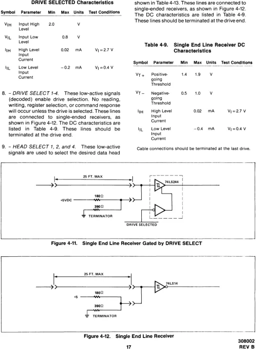
8. - DRIVE SELECT 1-4. These low-active signals (decoded) enable drive selection. No reading, writing, register selection, or command response will occur unless the drive is selected. These lines are connected to single-ended receivers, as shown in Figure 4-12. The DC characteristics are listed in Table 4-9. These lines should be terminated at the drive end.
9. - HEAD SELECT 1,2, and 4. These low-active signais are used to select the desired data head
I ..
2!i, FT. MAX [image:22.612.57.570.61.759.2]for reading or writing. Head selection decoding is shown in Table 4-13. These lines are connected to single-ended receivers, as shown in Figure 4-12. The DC characteristics are listed in Table 4-9. These lines should be terminated at the drive end.
Table 4·9. Single End Line Receiver DC Characteristics
Symbol Parameter Min Max Units Test Conditions
VT+ Positive- 1.4 1.9 V
going Threshold
VT- 'Negative- 0.5 1.0 V
going Threshold
IIH High Level 0.02 mA VI =2.7 V
Input Current
IlL Low Level -0.4 mA VI =0.4 V
Input Current
Cable connections should be terminated at the last drive.
r - - - ,
I
--~)
»)...---4
">--+--+---I180n
+5VDC - "1M
r
,_~~""'~,....n---'
J
TERMINATOR)
DRIVE SELECTED
Figure 4-11. Single End Line Receiver Gated by DRIVE SELECT
---~) ~>---~.)
J---I~1--4L-S-14---180n
V
I
25 FT. MAXI
TERMINATOR
Figure 4-12. Single End Line Receiver
17
308002
10. - READY. This low-active signal from the drive lindicates that the drive is up to speed and ready to read, write, or seek. This line is driven by a 75462 open collector driver, as shown in Figure 4-13. The DC characteristics are listed in Table 4-10. This line should be terminated at the controller end.
11.-I'NDEX. This low-·active signal occurs once per revolution and indicates the beginning of a track. This line is driven by a 75462 open collector driver, as shown in Figure 4-13. The DC characteristics are listed in Table 4-10. This line must be terminated at the controller end.
12. - SECTOR MARK. This low-active signal in-dicates the beginning of a sector. This line is driven by a 75462 open collector driver, as shown in Figure 4-13. The DC characteristics are listed in Table 4-10. This line must be terminated at the controller end.
Table 4·10. Sin"le End Line Driver DC Char,acteristics
Symbol Parameter Min Max Units Test Conditions
IOH High Level 0.1 mA
Output Current
IOL Low Level 30e mA
Output Current
VOH High Level 2.4 V
Output Voltage
VOL Low Level 0.8 V IOL = 300 mA
Output Voltage
This line must be terminated at the controller end.
13. +, - WRITE DATA. WRITE DATA is a NRZ serial
data signal synchronous with WRITE CLOCK. WRITE DATA is received by an RS422 type differential line receiver as shown in Figure 4-14. The DC characteristics are listed in Table 4-11. This line should be terminated at the drive end.
14. +, - WRITE CLOCK. This signal is switch se-lectable. It can be a square wave signal from the controller which is phase locked to the WRITE DATA, or if the switch is enabled, it can be a reference signal from the drive to the controller to provide clocking and synch ronization for WRITE DATA. The controller should be designed so that WRITE DATA is stable at the drive connector during the negative transition of WRITE CLOCK. WRITE CLOCK is received by an RS422 type differential line receiver, as shown in Figure 4-14. The DC characteristics are listed in Table 4-11. These lines should be terminated at the drive end. If long cables are used, cable delays must be considered.
15. +, - READ/REFERENCE CLOCK. This square
wave signal provides clocking and synchroniza-tion for reading and writin9 data. It is derived from either the servo clock or the VFO synchronized to the READ DATA signal. It is driven by an RS422 type differential driver, as shown in Figure 4-14. The DC characteristics are listed in Table 4-12. These lines should be terminated at the controller end.
16. +, - READ DATA. This serial NRZ signal is used to transmit data from the drive to the controller. This output is valid 10 microseconds after READ GATE is enabled. It is driven by an RS422 type differential driver, as shown in Figure 4-14. The DC characteristics are listed in Table 4-12. These lines should be terminatecl at the controller end.
. _
-75462
DRIVE SELECTED
TERMINATOR +5
I
II 25 FT. MAX •Y
180Q---~>>---~)
-390Q
Figure 4-13. Single End Line Driver
Table 4·11. Differential Line IReceiver DC Characteristics
Symbol Parameter Min Max Units Test Conditions
VTH Differential 0.2 V Input
High Threshold
VICR Common ± 15 V Mode Input
Flange
II(REG) Receiver 2.3 mA Input
Current
Table 4·12. Differential Line Driver DC Characteristics
Symbol Parameter Min Max Units Test Conditions
- - - ---
---~--VOH High Level 2.5 V 10H = -20 mA Output
Voltage
VOL Low Level 0.32 V IOL=20 mA Output
Voltage
10Z Output Off ±0.02 mA Current
10H High Level -20 mA Output
Current
10L Low Level +20 mA Output
Current
lOS Short Circuit -30 -150 mA Output
Current
Note: The last drive in a string should be terminated.
4.6.2 Serial Data Transfer Control Signals. Of the interface signals described in Section 4.6.1, there are several that are used specifically to facilitate serial data transfer between the disc drive and the controller. These are described below, with additional details.
1. INDEX - The INDEX pulse occurs whenever the servo track index mark is detected, to indicate the beginning of a track.
2. READY-The READY signal indicates that the selected drive is ready to read, write, or seek. When READY is false, the controller should not initiate WRITE, READ, or SEEK commands. However, READY will go false when a SEEK command is initiated. READY will later go true when the head carriage is positioned on the specified cylinder, if no fault condition exists.
3. SECTOR MARK - The SECTOR MARK pulse occurs at the beginning of each sector (sector size is selectable by setting the appropriate DIP switches on the Main PCB).
4. HEAD SELECT 1, 2, and 4 -These low-active Signals are used to select the data head, as shown in Table 4-13.
Head Select
1
Table 4·13. Head Selection.
Head Select
2
Head Select
4
Selected Head
3350
6650 15450
High High High Zero Zero Low High High One One High Low High Two Two Low Low High Zero" Three High High Low Zero" Four
Low High Low One" Five High Low Low Two" Six
Low Low Low Zero * Zero" t *Selected by default because of the number of heads available. tan drives with the Main PCB below EC1719 a drive fault will
occur.
3487 OR 75113
I...
25 FT. MAX ..I
DATA
ENABLE
n - -____ --<~(---~)
~----_____i __
_<
~<--->~ > - + - -___ - - - 4 100 11Figure 4··14. Differential Line Drivers and Receivers
19
5. WRITE GATE - WRITE GATE when active, en-ables data to be written on the disc. READY must be true before write gate is activated.
Table 4·14. Drh,e Fault Conditions
1. WRITE GATE without write current at the head. 2. Write current at the head without WRITE GATE. 3. WRITE GATE without READY.
4. WRITE GATE with WRITE PROTECT.
5. WRITE GATE occuring between INDEX and the first SECTOR MARK when the Skip Defect Record is protected,
6. More than one head selected. 7. No transitions during write. 8. Spindle speed error.
9. RESET while drive is Sequenced Up. -10. Off-Track condition when track following.
(READY true) '11. Failure to Restore.
"12. Software Error (time'-out of watch dog timer).
6. WRITE CLOCK - WI=tITE CLOCK provides clock-ing and synchronization for WRITE DATA. The controller generates WRITE CLOCK by echo-ing the READ/REFERENCE CLOCK signal back to the drive, with suitable phase delay relative to WRITE DATA.
7. WRITE DATA - WRITE DATA provides the data to be stored on the disc. N RZ (non-return-to-zero) data is required for WRITE DATA. READ/ I=tEFERENCE CLOCK (received from the drive) is used by the controller to clock WRITE DATA on the positive edge. READ/REFERENCE CLOCK is then retransmitted to the drive as WRITE CLOCK. The negative edge of WRITE CLOCK is used to strobe WRITE DATA into the drive's encoder circuitry.
8. READ GATE-RE~~D GATE must be enabled in a gap area (all Os recorded), and at least 9 mi-croseconds before the sync byte. READ GATE enables the VFO clock to synchronize with the information from the read head. Activating READ GATE during a data record may cause the VFO to spuriously lock in an incorrect phase relationship for decoding the recorded information.
8.6 microseconds after the leading edge of READ GATE, the internal READ CLOCK signal is enabled to the IQEAD/REFERENCE CLOCK interface signal lines.
9. READ/REFERENCE CLOCK - READ/REFER-ENCE CLOCK provides clocking and synchron-ization for reading and writing data. When
READ GATE is not active, READ/REFERENCE CLOCK is switched to the PLO clock, which is phased locked to the servo signal. A change in the phase of READ/REFEI=tENCE CLOCK will occur when it is switched between the servo and VFO clocks.
10. READ DATA - Data from the drive is in serial N RZ (non-return-to-zero) form, and is synchron-ized with READ/REFERENCE CLOCK after a 10 microsecond delay from the leading edge 9f READ GATE. READ DATA may not be valid for the first 10 microseconds after READ GATE is enabled.
4.6.3 User·Accessible Re~,isters. The user's controller sends control commands and target cylinder addresses to the disc drive via the eight bidirectional bus lines DBUS 0-7. The disc drive sends status informati()n and current cylin-der address information to tht9 controller via these same eight lines. DBUS 0-7 is a tri-state bus, and thus these lines present an open circuit to the controller's data bus unless they have been acti-vated by DRIVE SELECT. An a.ctive DRIVE SELECT combined with an active WFt enables the drive's line receivers on DBUS 0-7, so that the informa-tion on the bus can be written into the drive's three control registers. An active DRIVE SELECT combined with an active RD enables the drive's line drivers on DBUS 0-7, so that the information in the drive's three status-likt9 registers can be re-turned to the controller. The following six registers are involved:
The COMMAND REGISTER receives and stores commands from the controllf~r.
The TARGET ADDRESS REGISTER - UPPER BYTE receives and stores the two or three most significant bits of the desireel cylinder address.
The TARGET ADDRESS REGISTER - LOWER BYTE receives and stores the eight least signifi-cant bits of the desired cylinder address.
The STATUS REGISTER holds current drive status information.
The CURRENT ADDRESS REGISTER - UPPER BYTE holds the two or three most significant bits of the current cylinder address.
The CURRENT ADDRESS REGISTER- LOWER BYTE holds the eight least significant bits of the current cylinder address.
ap-propriate combinations of address lines A1 and
AD, and the WR or RD signal as shown in Table
4-15. Note that the command and target address registers are write-only, while the status and cur-rent address registers are read-only.
4.6.4 Commands. Table 4-16 lists the command codes for the valid commands. The com-mands are discussed individually following Table 4-16.
Table 4·15. Register Selection
RD WR A1 AO Selected Register
---.-~~-.-~--0 0 0 Command Register
0 0 Target Address - Upper Byte
0 0 Target Address - Lower Byte
0 0 0 Status Register
0 0 Current Address - Upper Byte
0 0 Current Address - Lower Byte
Note: 1
=
Active, 0=
Inactive.Table 4·16. Command Code Summary
DBUS
Command Name 7 6 5 4 3 2 1 0
Sequence Up
a a a
()a a a
1Sequence Down
a a a
()a a
1a
Restore
a a a
()a a
1 1Seek
a a a
()a
1a a
Fault Reset
a a a
()a
1a
1Read Drive ID
a a a
1a a a a
Read Bytes/Sector
a a a
1a a a
11. Sequence Up The Sequence Up command
causes the disc drive spindle motor to power up. The rotational speed of the disc is monitored, and after the drive is up to speed, the heads are positioned to cylinder zero. The drive presents BUSY status (BUSY bit set in the status register) while Sequence Up is in process. At the suc-cessful completion of Sequence Up, BUSY is cleared and CYLI N DER ZERO, SEEK COM-PLETE, and READY are set. If Sequence Up is unsuccessful, WRITE PROTECT and DRIVE FAULT are set.
2. Sequence Down The Sequence Down
com-mand causes the heads to be positioned to the landing zone, and the spindle motor to be
stop-21
pede WRITE PROTECT status is set at the com-pletion of Sequence Down.
3. Restore The Restore command causes the
head carriage to be positioned to cylinder zero. The drive Restores automatically on Sequence Up, or when a SEEK FAULT is detected. If the Restore command is unsuccessful, the heads will be positioned to the landing zone, and DRIVE FAULT status will be set. If the drive is not se-quenced up, the Restore command will function as a Sequence Up Command.
4. Seek The Seek command causes the drive to
seek to a specified cylinder. Prior to issuing the Seek command, the controller must place the desired cylinder address in the target address registers. Upon receipt of the Seek command, the drive clears READY status and sets BUSY, while moving the head carriage to the correct cylinder. When this has been done, the drive sets READY and also sets SEEK COMPLETE status. If the Seek command is unsuccessful, the drive Restores to cylinder zero, and sets CYLINDER ZERO and SEEK FAULT status.
5. Fault Reset The Fault Reset command clears
the two fault conditions - SEEK FAULT and DRIVE FAULT.
6. Read Drive ID The Read Drive ID command
loads the drive ID into the lower byte of the cur-rent address register, and clears READY status. The controller may then retrieve the information by reading the lower byte of the current address register. The values of the ID code for various PRIAM disc drives are given in Table 4-17.
After the DRIVE ID Information has been read by the controller, a Sequence Up or Restore command must be issued to bring the drive back to the READY state. In general, the current address registers contain the current cylinder address if the drive is READY, and the last re-quested parameter information if the drive is not READY.
7. Read Bytes per Sector The Read Bytes per
Sector command loads the number of bytes per sector into the current address registers, and clears READY status.
As with the Read Drive ID command, a Se-quence Up or Restore command must be issued to bring the drive back to the READY state.
Table 4·17. Drive 10 Assignments
ID Code (Hex) Drive Designation
---~--~- _ _ _ _ _ _ _ ••. _____ • _ _ _ _ _ _ _ _ _ _ _ _ _ ~._
'_"0-00 Not Valid 01 DISKOS 3350-01
or 3350-10 (20, 160 bytes/track) 02 DISKOS 3350-01 (19,960 bytes/track) O:~ DISKOS 3450 (12,960 bytes/track) 04 DISKOS 3450 (13,440 bytes/track) O~) DISKOS 7050 (13,440 bytes/track)
Q{) DISKOS 6650 O? DISKOS 15450 OB-OF Reserved 10 Reserved 1'1 DISKOS 1070-1 12 CD80m, 1 :~ CD8010 14 Reser-vied 1'-,) DISKOS 1070-2
113 DISKOS 1070-3 H-FF Reserved
4.6.5 Register Bit Definitions. Register Bit Defi-nitions are presented in Table 4-18 and Table 4-19.
liable 4·18. Status Register Bit Definitions
Bit Name Description
0 11EADY The drive is up to speed, the servo system is locked onto a servo track, and the drive is able to read, write or seek.
SEEK A seek operation has been completed. COMPLETE This bit is not valid when the BUSY bit
is set.
2 SEEK A fault was detected during a seek oper-FAULT ation. This bit is not valid when the
BUSY bit is set.
3 CYLINDER The head carriage is at cylinder zero. ZERO This bit is not valid when the BUSY bit
is set.
4 BUSY The drive is in the process of executing a comrnand.
Table 4·18.
Bit Name 5 DRIVE
FAULT
6 WRITE PROTECT
Status Regis1ter Bit Definitions (cont'd.)
Description
A fault was detected during a write oper-ation, or a drive unsafe condition was detected.
The selected head is write protected. WRITE PROTECT is set by switches on the main PCB. The entire drive is write protected when it is not sequenced up. 7 COMMAND The controller attempted to write to a
REJECT register when the drive was not READY, or an invalid cornmand was received by the drive. This bit is not valid when the BUSY bit is set.
Table 4·19. Target and Current Cylinder Address Register Bit Definitions
Elit Number
Byte 7 6 5 4 3 2 0
Upper Byte 0 0 0 0 0 C10 C9 C8 Lower Byte C7 C6 C5 C4 C3 C2 C1 Co
As indicated in Table 4-19, up to eleven bits of in-formation can be stored in the address registers. This information may be the target cylinder ad-dress, the current cylinder adad-dress, or the re-quested parametric information, such as bytes per sector or drive ID. C10 is the most significant bit, and
Co
is the least significant bit.4.6.6 Interface Timing. TI"lis section discusses the timing requirements for the various op· erations performed on the drive interface.
1. Register Load Timing Register load timing is
[image:28.614.59.569.68.726.2]shown in Figure 4-15. The AC characteristics are listed in Table 4-20.
Table 4·20. Register load AC Characteristics
Symbol Parameter
tAW Address stable before WR tWA Address hold time for WR tww WR pulse width
tDW Data set up time for WR tWD Data hold time for WR
Recovery time between WR
Min Max Units
60
:30
100
60
30
200
ns ns ns ns ns ns
2. Register Read Timing Register read timing is
shown in Figure 4-16. The AC characteristics are listed in Table 4-21.
Table 4·21. Register Read AC Characteristics
Symbol Parameter
Address stable before RD Address hold time for RD RD pulse width
Data delay from RD RD to data floating
Min Max Units
60
30
100
10
60
40
ns ns ns ns ns
ADO-1
DRIVE SELECT
~r-=11:.:====~====-t-AW---=----=---~"-I---'--1-f=
tWAr
---'~~~
.. :-=--=--=--t-D-W---
+---i-~
-.... -'---tw-oF=
DBUS
... ---- tRV
---~L-________________________________________________________________________________ . ___
ADO-1
DRIVE SELECT
DB US
Figure 4-15. Regi