Structural Design Optimization of a High Speed
Synchronous Reluctance Machine
Mauro Di Nardo, Giovanni Lo Calzo, Michael Galea, Chris Gerada
Power Electronics and Machine Control Group, University of Nottingham, UKAbstract—Synchronous reluctance machines, including the permanent magnet assisted variants are competitive motor topologies if the application requires high efficiency and a cost effective solution with a high flux weakening capability. However, increasing speeds incur challenging design and development decisions, in order to find an optimal solution between the machine performance and its structural integrity. In this paper, a comprehensive design procedure for such machines is presented, where a 5kW, 80000 rpm synchronous reluctance machine is considered. The proposed strategy consists of a two-step proce-dure in which the electromagnetic and structural designs have been properly decoupled dividing the design space in two subsets. Each subset mainly affects the electromagnetic or the structural performances. Several structural design optimizations have been performed with the aim of finding the optimal trade-off between the rotor geometrical complexity (i.e. computational time) and the electromagnetic performance. The results shown in this paper validate the proposed design strategy which can be used as general guidelines on the structural design of synchronous reluctance machines.
Index Terms—Finite element analysis, high speed, multi-physics design, multi-objective optimization, rotor structural design, synchronous reluctance machines.
I. INTRODUCTION
Synchronous reluctance (SyR) machines are currently expe-riencing a revamped industrial interest mainly because when compared to the more common induction machines (IM), they can achieve considerable volume reduction and/or an im-provement in operational efficiency [1]. Along with the higher efficiency, high transient overload capability [2], simple rotor construction and no need of rare earth permanent magnets are the other main advantages of SyR machines which make them a low cost alternative. On the other hand, high torque ripple, low power factor and a slightly reduced flux weakening range (compared to an IM drive having the same converter kVA rating) are its main disadvantages. The transversal laminated SyR machine with multiple flux barriers has been extensively studied since the 1990s [3]. In particular considerable research has been focused on torque ripple minimization and on maximization of the saliency ratio [4]. A number of different techniques for torque ripple minimisation have been devel-oped, including rotor skewing, an appropriate choice of the airgap positions and the number of flux barriers with respect to the number of stator slots [5]. Other techniques address optimization of the flux barrier and end-barrier geometries [6]. Considerable improvements especially related to the power factor and the flux weakening capability can be achieved by the PM-assisted variant (PMaSyR) where low energy density PMs are inserted in the rotor flux barriers [7]. These machine topologies, if properly designed, can achieve a wide constant power speed range. However, as speed increases, significant effort is required to achieve a good trade-off between the
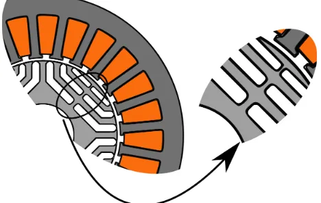
[image:1.595.312.546.592.740.2]electromagnetic performance and the rotor structural integrity. The latter is practically dependent on the so-called iron bridges, which can be observed in Fig. 1. If these bridges are made to be wider for the sake of the rotor robustness at high speed, then this comes at the cost of a reduction in torque and power factor. Traditionally, all the above has significantly limited the use of SyR and PMaSyR machines for applications operating in medium to high speed ranges. However the ever increasing availability of new electrical steel materials, specifically designed to meet the higher demand in yield strength with minimum effect on the electromagnetic characteristics, has encouraged the research community to invest more in the concept of applying SyR machines in high speed applications [8]. When compared to other high speed machine topologies, mainly PM synchronous machines (PMSM), IMs and switched reluctance (SR) machines, the high speed SyR machine (HS-SyR) has the following benefits. They do not require any rotor retaining system which make the rotor construction more complex and increase the rotor losses, they reduce the risk of uncontrolled voltage operation in case of inverter fault and they still exhibit high efficiency and torque density without the need of using rare earth permanent magnets. In order to achieve good HS-SyR designs, able to satisfy the performance and rotor integrity requirements, several multi-physics design approaches have been proposed [8], [9]. It has also been shown [10] that dividing the de-sign procedure in two steps, i.e. the electromagnetic dede-sign followed by a proper mechanical design, is a very effective design approach both from computational effort point of view and performance of the final design. Considering that the elec-tromagnetic design and analysis of SyR machines had been extensively covered in other works, then this paper is mainly focused on the structural design aspects. Several attempts
[11], [12] have been made in order to identify guidelines and analytical rules to design the iron bridge dimensions. The most common [11] is able to estimate the total iron bridge per flux barrier; however this strongly depends on the rotor geometry under consideration (end barrier geometry, fillet radii of the barrier corners, etc.). This analytical formulation therefore necessitates the use of safety factors that have to be preliminary identified by finite element (FE) analysis or by utilising the designer experience. Also, such analytical model cannot predict the optimal spatial distribution of the estimated total bridge, i.e. subdivision between tangential and radial ribs and the positions of the latter along the flux barrier. The aforementioned model is thus usually used to initially estimate the total iron bridge dimensions but a structural FE design stage is always needed to verify the initial guess and individuate its optimal spatial redistribution [8]. Regarding the latter, in [13] it has been shown that the position of the radial ribs play a key role in the minimization of the maximum von Mises stress. However such results are obtained by means of a parametric study which obviously does not take into account the interaction of all rotor parameters on the structural performances. Considering all the above, it can be deduced that the major issues in the rotor structural design of HS-SyR machines are the high number of geometrical degrees of freedom (GDOF) and the lack of an accurate analytical model. Thus, in this work a stochastic optimization algorithm (OA) coupled with a structural FE is used to carry out the mechanical design of a 5kW - 80000 rpm synchronous reluctance machine. It is important to note that FE-based design by means of OA has the serious drawback of considerable computational burden. This is due to 1) the long FE simulation time needed to evaluate a single rotor candidate and 2) the high number of FE evaluations required by the OA to converge. The first is related with the trade-off between required accuracy (which mainly depends on the FE mesh setting) and to the single FE simulation time. The second depends on the selected OA, the number and type of objective functions and the number of input variables (i.e. geometrical complexity) which defines the research space dimension. In particular the latter constitutes a crucial aspect, therefore this paper deeply investigates the compromise between geomet-rical complexity, obtainable performance and computational time for a given OA and optimization goal. In the next section the preliminary design choices, the rotor parametrization, the design procedure along with the electromagnetic and structural objectives are presented. Section III outlines the results of the structural design optimizations both neglecting and considering the influence of the rotor-shaft coupling on the mechanical designs. In Section IV, a detailed electromagnetic
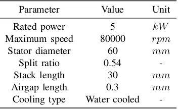
TABLE I:Machine specifications and main dimensions
Parameter Value Unit
Rated power 5 kW
Maximum speed 80000 rpm
Stator diameter 60 mm
Split ratio 0.54
-Stack length 30 mm
Airgap length 0.3 mm
Cooling type Water cooled
-analysis of the final design is reported while the last section draws the conclusive remarks.
II. PROBLEMSTATEMENT
A. Specifications and preliminary design considerations
The external dimensions of the HS-SyR machine have been imposed by the constraints of the specific application summarized in Table I along with the other main geometrical parameters. The airgap thickness is fixed to the minimum allowed by the bearing manufacturer being the average torque and power factor of a SyR machine monotonically decreasing as the airgap length increases [8]. A distributed winding configuration is obviously chosen to limit the harmonic con-tent of the stator magneto motive force which negatively influences the iron losses and the reluctance torque [14]. The number of poles is set to 4 with the aim of limiting the fundamental frequency. The number of stator slots and the number of rotor flux barriers are tightly related if a good trade-off between average torque, torque ripple, iron losses and rotor construction complexity has to be achieved. A 24 stator slots, 3 flux barriers has been chosen as the best compromise between electromagnetic performance and manufacturing feasibility. Regarding the lamination material, each product available on the market mainly excels in only one of the following features: saturation flux density, specific iron losses and yield strength. For a HS-SyR machine, if the same material is considered for both stator and rotor, its optimal choice requires an appropriate trade-off study comparing laminations having different characteristics [15]. In this case study two different materials for the stator and rotor have been adopted. In particular, the stator is realized using an electrical steel with low specific iron losses (10 W/kg at 1T/400Hz) while for the rotor a high strength lamination material has been adopted. The latter has a yield point of 822 MPa at the expense of an increased specific iron loss (45 W/kg at 1T/400Hz). Starting from the above constraints and choices and considering a rated torque of 0.6 [Nm] and a rated current density of 10 [A/mm2], the main stator parameters
have been analytically determined [16]. A lumped parameter thermal network is then been employed in order to verify the thermal limits of the machine. Considering that the scope of this work is the rotor design, then the stator is assumed fixed for the rest of the paper.
B. Rotor parametrization
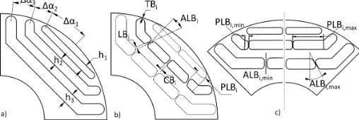
Different rotor flux barrier parametrizations have been pre-sented in literature [17], [18]. All of them show that the flux barrier and end barrier geometry play a key role on the torque maximization and torque ripple reduction [19]. It has been shown that increasing the geometrical complexity of the flux barrier profile slightly improve the electromagnetic perfor-mances when compared to simpler geometries [18]. However this comes at the cost of a significantly more complex design since the number of rotor parameters describing the barrier increases with the geometrical complexity. Considering all the above, a rotor geometry described by a reduced number of parameters has been selected and this is shown in Fig. 2a. Each flux barrier is made of straight segments and is unequivocally identified by the radial thicknesshi, the angular position at the
the structural integrity at high speed. In particular, except for the most external barrier, all of them include tangential, central and lateral iron ribs T Bi, CBi and LBi, and the latter can
assume whatever geometrically feasible position P LBi and
bending angle ALBi along the straight part of the barrier
[image:3.595.42.296.161.246.2](Fig. 2b). Each corner created by the radial posts is rounded with a radius equal to one third of the height of the respective barrier.
Fig. 2: a) Parametrization of the main part of the flux barriers, b) Parametrization of the iron bridges, i.e. thickness’s, position and bending angle of the lateral rib for one flux barrier, c) minimum and maximumP LBiand ALBi
C. Design procedure
The adopted rotor design method of the HS-SyR machine under study consists of a two-step procedure where an electro-magnetic design is followed by a proper mechanical design. This strategy is based on the assumption that the design variables can be divided in two subsets, and each of them is separately sequentially identified.
• The first subset contains 6 geometrical parameters, shown in
Fig. 2a, mainly affecting the electromagnetic performances, i.e. radial height hi and angular position ∆αi of each
barrier.
• The second includes 12 variables, shown in Fig. 2b, pri-marily influencing the von Mises stress distribution of the rotor, i.e. all the iron bridge dimensions (T Bi, CBi and LBi), and the position and bending angle of the lateral rib
(P LBi andALBi).
The hypothesis behind this subdivision is the weak impact of the first subset of parameters on the structural performance and of the second subset on the electromagnetic ones. The above procedure is valid only when the considered structural design criterion directly or indirectly leads to the minimization of the iron bridge thicknesses. This design concept has already been validated in [10], where it has also been shown that, if a FE based design assisted by OA both for structural and electromagnetic aspects is adopted, a substantial reduction of the computational time is achieved.
D. Electromagnetic and structural performance indexes
Regarding the electromagnetic design step, two design approaches can be implemented: the first one analytical es-timates the main rotor geometrical parameters and make use of a FEA as refinement stage to take into account the non-linearities and the disregarded aspect of the analytical model; the second one is FE-based design assisted by OA. In both cases, average torque and torque ripple are the most important performance indexes to consider during the rotor design. In this case study, the second approach has been adopted and more details can be found in [10] and are omitted for the sake of brevity.
From a structural design perspective, the lack of an accurate mechanical analytical model and the high number of geomet-rical degrees of freedom involved in the rotor design has led to the adoption of structural FE-based assisted by OA design approach. The rotor structural integrity at the maximum speed is obviously guaranteed if the maximum von Mises stress experienced in the rotor lies below the yield strength of the lamination material. Consequently during the optimization if the maximum stress exceeds the limit, the rotor candidate has to be penalized. However several combinations of the iron bridge dimensions and distributions can assure the previous essential safety condition, therefore another criterion has to be identified. A possible solution is reported in [10], where the rotor is designed maximizing the mechanical exploitation of the iron bridges; such criterion is fulfilled if the same maximum stress is measured in each structural rib. By doing so, the thicknesses of the iron bridges are implicitly minimized leading to highest torque possible for a given stress limit. The major drawback of such structural criteria lies on the difficulty of evaluating this objective function and on its high non-linearity which prevents the OA to achieve repeatable results. Another possible structural design criterion can be represented by the minimization of the average total bridge per flux barrier, defined as:
AT B= 1
n n X
i=1
(2·T Bi+ 2·LBi+CBi) (1)
where n is the number of flux barrier (3 in our case study). The application of such criteria lies on the hypothesis that the decrement of the average torque dT caused by the increment of an iron bridge thickness dB is independent from the real position of the rib’s increment. In other words, wherever dB is allocated, such as on the tangential, lateral or central rib and whatever the position of the lateral one is, the loss of the torque dT remains the same. As verified later, the minimization of the average total bridge per flux barrier AT B subject to the constraint on the maximum stress (FE calculated), which have to be lower than 657 MPa (i.e. 80% of the yield strength, 822 MPa), will lead to rotor structures with the highest average torque for a given stress limit.
III. STRUCTURAL DESIGN OPTIMIZATIONS
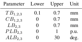
In this work a differential evolution optimization algorithm has been selected to perform the HS-SyR rotor structural design. This choice comes from a preliminary optimization campaign in which the convergence time and repeatability of the results of the most common stochastic OAs have been compared. This algorithm definitely gives the best results for the objective problem under consideration. The boundaries of the research space are shown in Table II. The lower boundaries of the radial ribs thicknesses (LBi,CBi) are zero,
TABLE II: Boundaries of the research space
Parameter Lower Upper Unit
T B1,2,3 0.1 0.7 mm
CB1,2,3 0 0.7 mm
LB2,3 0 0.7 mm
P LB2,3 0 1 p.u.
ALB2,3 0 30 deg.
distributions have been optimized. In particular, five rotors have been considered and each of them is described in the following:
• 4 GDOF has equal tangential bridge thicknesses T B, different central ribs CBi and do not present the lateral
postsLBi for the second and third barriers;
• 6GDOF features equal tangential bridge thicknessesT B, different radial ribs CBi, LBi but the position P LBi and
the bending angleALBi of LBi are set to zero;
• 8GDOF can assume whatever value inside the boundaries
of the tangential, central and lateral bridgesT Bi, CBi, LBi,
but the variablesP LBi andALBi are still set to zero;
• 10GDOF respect to the previous, has the further possibil-ity of varying the positions of the lateral postsP LBiinside
the defined bounds;
• 12GDOF can additionally present a bending angle of the lateral ribALBi different than zero.
Each rotor structure has been optimized carrying out 10 optimization runs in order to evaluate the repeatability of the results. As the GDOF increases, the number of performed functional evaluations has been incremented allowing the algorithm to converge as it will be discussed in the next paragraph. In order to achieve the most accurate result in a reasonable amount of time, the FE settings have been customized with the aim to refine the mesh only in the critical parts of the rotor, i.e. the iron bridge regions. Adopting these settings, the FE evaluation of the von Mises stress distribution needed to extrapolate the maximum stress and the computation of the objective functionAT B, requires 8 seconds per rotor (on an Intel Core i7, 3.6 GHz, 16GB RAM).
A. Optimization results
The average total bridge (ATB) evolutions during the op-timization of all rotor structures are shown in Fig. 3. For each considered rotor geometry, the best and the worst runs have been reported. Analysing the optimization evolutions, the following considerations regarding the trade-off between obtainable performance (in this case AT B) and required functional evaluations can be drawn.
• When moving from a 4 to 6 GDOF rotor, it is always possible to achieve a substantial reduction (35-40%) of the AT B even with the same functional evaluations.
• Comparing 6 with 8 GDOF rotors, then to obtain a
reduction of 5% or less of the optimization goal, the functional evaluations have to be almost doubled (from 5400 to 10000).
• Going from 8 to 10GDOF rotors, then to assure an addi-tional improvement of 5% (in the best case), the evaluation calls have to be at least increased by 35%.
Fig. 3: Average total bridge evolutions for the 5 considered rotor geometries
• A further increment (35%) of the number of functional evaluations, going from 10 to 12 GDOF rotors will not result in any improvement.
It can also be argued that the optimizations of the rotor having 12 GDOF could achieve better performance if the number of functional evaluations is increased. However, it has to be considered that one optimization run (of the 12GDOF rotor) shown here has been obtained after 38 hours of calculations and the increment of the functional evaluations would have made the computational time impracticable.
B. Analysis of the optimized rotor geometries
The improvements of the mean torque ∆T (calculated at 4/3rdthe rated current) caused by the reduction of the average
total bridge ∆AT B respect to the simplest rotor as function of the GDOF are shown in Fig. 4. The final results of the best and worst optimization runs are reported. Considering the best case scenario for each GDOF, it can be deduced that passing from rotor geometries comprising:
• 4 to 6GDOF, then the 41% reduction ofAT B causes the increment of the mean torque of about 8.6%;
• 6 to 8 GDOF, then the additional 5.1% AT B decrement leads to another 1.5% torque improvement;
• 8 to 10GDOF, then the extra 9.8% decrement of theAT B induces the production of 1.8% more torque;
• 10 to 12 GDOF, then there is no change in AT B and
therefore in the mean torque.
[image:4.595.88.245.66.147.2]Even when considering the worst optimization runs, these considerations are still valid, in fact the improvements of the mean torque is remarkable at the beginning (4 to 6 GDOF) and tends to weaken as GDOF increases, until it becomes null for the most complicated rotor structure. Table III
[image:4.595.319.555.614.732.2]Fig. 5:Von Mises stress distribution of the optimized rotor geometries with a 1:30 scale for the deformation
reports the iron bridge dimensions and the electromagnetic performances for the optimal rotors of each best optimization run while Fig. 5 show their von Mises stress distributions. It is worth to underline that passing from rotor with 6 to 8, 10 or 12GDOF, the number of radial bridges (N RB) decreases from 7 to 5. In particular, comparing the rotor with 6 and 8 GDOF, the latter does not have the lateral ribs on the second barrier but it has a bigger tangential bridgeT B2; furthermore
the dimension ofLB3is remarkably reduced. These changes
simplify the rotor construction, especially in case of small rotor bore diameter, because it is preferable to have a reduce number of iron bridges with a larger thickness than more thinner ribs. However this advantage comes at the price of an increased torque ripple with respect to the initial machine. In fact the torque ripple of the machine without any radial bridges (and all T Bi equal to 0.3mm), which is the output
of the electromagnetic design stage, is 1.14% (in standard deviation, std). More the tangential bridge thicknesses vary from the initial value (0.3 mm), and/or more they differ respect to each other, more the torque ripple changes, as it is for the rotors with 8 and 12GDOF (see Table III). Differently from the other geometries, the rotors with 8 and 12 GDOF do not have tangential bridge thicknesses which increase from the outermost to the innermost barrier. All the optimized rotor present increasing central and lateral rib widths going from the outermost to the inner most barrier. Analysing the geometry with 10 GDOF, it has to be highlighted that the optimal positions of the lateral iron ribs are at 52% and 65% of the respective barrier lengths. This distribution achieves the best performance in terms of average total bridge and therefore electromagnetic torque. Comparing rotors showing 10 and 12 GDOF, since they have the sameAT Bs and so electromagnetic torque, it can be deduced that more than one
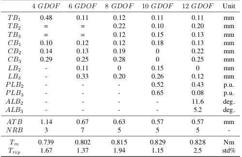
TABLE III: Geometrical parameters and electromagnetic perfor-mance of the optimal rotors
4GDOF 6GDOF 8GDOF 10GDOF 12GDOF Unit
T B1 0.48 0.11 0.12 0.11 0.11 mm
T B2 = = 0.22 0.10 0.20 mm
T B3 = = 0.12 0.15 0.13 mm
CB1 0.10 0.12 0.12 0.18 0.13 mm
CB2 0.14 0.13 0.19 0 0.22 mm
CB3 0.29 0.25 0.28 0 0.25 mm
LB2 - 0.11 0 0.15 0 mm
LB3 - 0.33 0.20 0.26 0.12 mm
P LB2 - - - 0.52 0.43 p.u.
P LB3 - - - 0.65 0.08 p.u.
ALB2 - - - - 11.6 deg.
ALB3 - - - - 5.2 deg.
AT B 1.14 0.67 0.63 0.57 0.57 mm
N RB 3 7 5 5 5
-Tm 0.739 0.802 0.815 0.829 0.828 Nm
Trip 1.67 1.37 1.94 1.15 2.5 std%
[image:5.595.303.553.446.499.2]optimal geometry exists for a given value of average total bridge per flux barrier. This indicates that the solution of the structural optimization problem, as it has been conceived here, for the rotor having 10 and 12 GDOF is not unique. This is also proved by the observation that the optimizations of the rotors with 10 and 12 GDOF are more likely to provide a different final geometry, when compared to the optimizations of the rotors having 4, 6 and 8 GDOF as it is shown in Table IV. The latter reports: 1) the standard deviation of the objective function stdAT B calculated over the 10 results obtained for each rotor, 2) the euclidean distances ED (evaluated considering the design variables) between the farthest and the nearest solution with respect to the average and 3) the difference∆EDbetween the previous two distances. Even if stdAT Bremains quite low for all the 5 sets of optimizations,∆ED, which clearly represents how much different the obtained results are in terms of geometry, is much bigger for the rotor with 10 and 12GDOF than the others with less degrees of freedom.
TABLE IV:Standard deviations of the objective functions and eu-clidean distances among the design variables calculated considering 10 optimization runs for each rotor geometry
4GDOF 6GDOF 8GDOF 10GDOF 12GDOF
stdAT B(%) 0.68 5.09 2.09 4.87 3.55
minED 0.015 0.024 0.018 0.093 0.171
maxED 0.082 0.097 0.106 0.5 0.565
∆ED 0.067 0.073 0.088 0.407 0.394
C. Rotor-shaft coupling influence
[image:5.595.41.291.599.761.2]8GDOF 12GDOF Unit
T B1 0.17 0.12 mm
T B2 0.26 0.15 mm
T B3 0.18 0.19 mm
CB1 0.11 0.10 mm
CB2 0.15 0 mm
CB3 0.31 0 mm
LB2 0 0.15 mm
LB3 0.4 0.28 mm
P LB2 - 0.6 p.u.
P LB3 - 0.53 p.u.
ALB2 - 9.6 deg.
ALB3 - 19.2 deg.
AT B 0.86 0.63 mm
N RB 5 5
-Tm 0.768 0.813 Nm
Trip 1.64 1.28 std%
Fig. 6 & TABLE V: Geometrical parameters, electromagnetic performance and von Mises stress distribution of the rotors optimized considering the interference pressure
anymore. In order to identify the influence on the rotor design due to the interference fit, several structural optimizations have been carried out considering the geometries having 8 and 12 GDOF taking into account the contact pressure. The calculation of the needed interference and the resulting pressure can be done analytically for simple cylindrical parts [20] while it requires a set of FE simulation in case of non-standard geometry. In this study the interference pressure used during the optimizations (kept constant at 50 MPa) has been analytically estimated approximating the rotor as a cylindrical component (i.e. without flux barrier) and then verified by FE for one rotor geometry. Table V reports the iron bridge dimen-sions and the electromagnetic performance of the optimized rotors while Fig. 6 shows their von Mises stress distributions. In this case, increasing the number ofGDOF (from 8 to 12) leads to an improvement in terms of average total bridge per barrier of about 26% which implies an increment of the torque of 6%. Obviously the better electromagnetic performance comes at the price of an increased computational effort. Comparing the final rotors with 8 and 12 GDOF (obtained with and without the interference pressure), it can be noticed that the average total bridgeAT B is incremented respectively of 35% and 10% to sustain the interference pressure and keep the maximum stress at the same level. It can be deduced that if the contact pressure is considered during the structural optimization, then the position and the bending angle of the lateral iron ribs (P LBi, ALBi) play a key role in the reduction
of the maximum stress and therefore the minimization of AT B.
IV. PERFORMANCES OF THE FINAL DESIGN
[image:6.595.45.286.51.225.2]According to the previous analysis, the rotor geometry with 12GDOF (optimized considering the rotor-shaft coupling by interference fit) shows the best performance. Such machine has been selected and further analysed by means of FEA. In particular, Fig. 7 shows the average and ripple of the torque as function of the current phase angle at different current levels. It is worth to notice that the torque ripple remains below 2% (std, i.e. 7% calculated considering the usual approach) over the whole current range at MTPA conditions. Figure 8 depicts the iron and joule losses and the efficiency as function of the current amplitude for the two different speeds. The efficiency (calculated considering also the windage and the AC copper
[image:6.595.312.556.57.180.2]Fig. 7:Average (continuous line) and ripple (dashed line) torque as function of the current phase angle for different currents
Fig. 8: Iron, joule losses (continuous lines) and efficiency (dashed lines) as function of current amplitude for 80 and 40 [krpm]
losses) is above 95% at the rated current (15 Apk) for both
considered speeds.
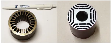
In order to validate all the above, a prototype of the selected rotor has been developed, as shown in Fig. 9, and it is currently under testing on an instrumented test-rig.
Fig. 9: Stator and rotor lamination stacks before winding and assembling (pictures are not shown in the same scale)
V. CONCLUSIONS
[image:6.595.313.552.225.344.2] [image:6.595.311.544.452.543.2]geometrical variables (so computational time), several rotor geometries showing different degrees of freedom (GDOF) in terms of iron bridge thicknesses and distributions have been optimized with and without the rotor shaft coupling influence. Neglecting the interference pressure during the design, as it is normally done in low-medium speed range application, the following conclusion can be drawn.
• As the geometrical complexity grows, the improvements of the mean torque is remarkable at the beginning (from 4 to 6 GDOF), then tends to weaken (from 6 to 10GDOF) until it becomes null for the most complicated rotor structure.
• The best compromise between obtainable performance and required computational time is achieved when adopting the geometry with 6GDOF. The latter is obtained optimizing a unique tangential bridge width (common to all barriers), the widths of the lateral and central ribs (which can be different for all barriers), and considering fixed the position and the bending angle of the lateral bridges.
• Adding only the possibility of having different tangential
bridge widths (i.e. adopting the 8 GDOF rotor) allows reducing the number of radial iron bridges. This can make the rotor manufacturing easier especially in case of small rotor diameter.
• The highest electromagnetic torque is achieved when the positions of the lateral bridges are also included in the structural optimization (i.e. adopting the rotor with 10 GDOF).
• If the positions and the bending angles of the lateral ribs are considered during the structural design, for a given average total bridge corresponds more than one rotor geometry. Consequently the solution of the structural optimization problem, as it has been conceived here, is not anymore unique.
When the interference pressure is considered during the struc-tural optimization (e.g. high speed applications):
• as GDOF rises, the average total bridge decreases, there-fore better performance can be obtained at the cost of an increased computational effort;
• the position and the bending angle of the lateral iron ribs play a fundamental role in the reduction of the maximum stress and so in the minimization ofAT B.
REFERENCES
[1] A. Boglietti, A. Cavagnino, M. Pastorelli, D. Staton, and A. Vagati. Thermal analysis of induction and synchronous reluctance motors. Industry Applications, IEEE Transactions on, 42(3):675–680, 2006. [2] G. Pellegrino, A. Vagati, B. Boazzo, and P. Guglielmi. Comparison
of induction and pm synchronous motor drives for ev application including design examples. Industry Applications, IEEE Transactions on, 48(6):2322–2332, 2012.
[3] D.A. Staton, T.J.E. Miller, and S.E. Wood. Maximising the saliency ratio of the synchronous reluctance motor. Electric Power Applications, IEE Proceedings B, 140(4):249–259, July 1993.
[4] A. Fratta, G. P. Toglia, A. Vagati, and F. Villata. Ripple evaluation of high-performance synchronous reluctance machines. Industry Applica-tions Magazine, IEEE, 1(4):14–22, 1995.
[5] A. Vagati, M. Pastorelli, G. Francheschini, and S. C. Petrache. Design of low-torque-ripple synchronous reluctance motors. Industry Applica-tions, IEEE Transactions on, 34(4):758–765, 1998.
[6] N. Bianchi, M. Degano, and E. Fornasiero. Sensitivity analysis of torque ripple reduction of synchronous reluctance and interior pm motors. Industry Applications, IEEE Transactions on, 51(1):187–195, 2015. [7] N. Bianchi, E. Fornasiero, and Soong Wen. Selection of pm flux linkage
for maximum low-speed torque rating in a pm-assisted synchronous reluctance machine. Industry Applications, IEEE Transactions on, 51(5):3600–3608, 2015.
[8] M. Palmieri, M. Perta, and F. Cupertino. Design of a 50.000 rpm synchronous reluctance machine for an aeronautic diesel engine com-pressor. InEnergy Conversion Congress and Exposition (ECCE), 2014 IEEE, pages 5138–5143.
[9] F. Cupertino, M. Palmieri, and G. Pellegrino. Design of high-speed synchronous reluctance machines. InEnergy Conversion Congress and Exposition (ECCE), 2015 IEEE, pages 4828–4834.
[10] M. Di Nardo, M. Galea, C. Gerada, M. Palmieri, and F. Cupertino. Multi-physics optimization strategies for high speed synchronous re-luctance machines. In Energy Conversion Congress and Exposition (ECCE), 2015 IEEE, pages 2813–2820.
[11] M. Barcaro, G. Meneghetti, and N. Bianchi. Structural analysis of the interior pm rotor considering both static and fatigue loading. Industry Applications, IEEE Transactions on, 50(1):253–260, 2014.
[12] A. Binder, T. Schneider, and M. Klohr. Fixation of buried and surface-mounted magnets in high-speed permanent-magnet synchronous machines. Industry Applications, IEEE Transactions on, 42(4):1031– 1037, July 2006.
[13] M. Di Nardo, M. Galea, C. Gerada, M. Palmieri, F. Cupertino, and S. Mebarki. Comparison of multi-physics optimization methods for high speed synchronous reluctance machines. InIndustrial Electronics Society, IECON 2015 - 41st Annual Conference of the IEEE, pages 002771–002776, Nov 2015.
[14] M. Gamba, G. Pellegrino, and A. Vagati. A new pm-assisted syn-chronous reluctance machine with a nonconventional fractional slot per pole combination. In Optimization of Electrical and Electronic Equipment (OPTIM), 2014 International Conference on, pages 268– 275.
[15] M. Palmieri, M. Perta, F. Cupertino, and G. Pellegrino. High-speed scalability of synchronous reluctance machines considering different lamination materials. InIndustrial Electronics Society, IECON 2014 - 40th Annual Conference of the IEEE, pages 614–620.
[16] A. Vagati, G. Franceschini, I. Marongiu, and G. P. Troglia. Design criteria of high performance synchronous reluctance motors. InIndustry Applications Society Annual Meeting, 1992., Conference Record of the 1992 IEEE, pages 66–73 vol.1.
[17] R. R. Moghaddam and F. Gyllensten. Novel high-performance synrm design method: An easy approach for a complicated rotor topology. Industrial Electronics, IEEE Transactions on, 61(9):5058–5065, 2014. [18] M. Gamba, G. Pellegrino, and F. Cupertino. Optimal number of rotor parameters for the automatic design of synchronous reluctance ma-chines. InElectrical Machines (ICEM), 2014 International Conference on, pages 1334–1340.
[19] M. Di Nardo, M. Degano, M. Galea, C. Gerada, M. Palmieri, F. Cuper-tino, N. Bianchi, and D. Gerada. End barrier shape optimizations and sensitivity analysis of synchronous reluctance machines. InIndustrial Electronics Society, IECON 2015 - 41st Annual Conference of the IEEE, pages 002914–002919, Nov 2015.
[20] Wei Tong. Mechanical Design of Electrical Motors.
BIOGRAPHIES
Mauro Di Nardoreceived the B.SC.(Hons.) and M.Sc.(Hons.) degrees in electrical engineering from the Politecnico di Bari, Italy in 2009 and 2012, respectively. He is currently working towards the Ph.D. degree in the Power Electronics, Machines and Control Group, at the University of Nottingham, UK. His main research interests are the high-speed electrical machines and their multi-physics optimization.
Giovanni Lo Calzo received the Master’s degree and the PhD degree from the University of Roma Tre, Italy, respectively in 2010 and 2015. From 2010 to 2011, he was a Research Assistant with the University of Roma Tre. He is currently a Research Fellow with The University of Nottingham, UK, in the Power Electronics, Machine and Control Group. His research interests are focused on power electronics converters for high speed machines, control and modelling of grid-tied and isolated inverters, output filter topologies.
Michael Galea received the Ph.D. degree in electrical machines design from The University of Nottingham, UK, in 2013. He is currently the Deputy Director of the Institute for Aerospace Technology with The Uni-versity of Nottingham. He is a Lecturer in Electrical Machines and Drives and Aerospace Systems Integration with the Department of Electrical and Electronic Engineering, The University of Nottingham. His current research interests include design, analysis, integration, and thermal management of electrical machines.