Factors Causing Undesirable Deformations during the Bending
of Extruded Sections
*Shuji Sakaki
1and Noah Utsumi
21
Department of Mechanical Engineering, Tokyo Metropolitan Institute of Technology, Tokyo 191-0065, Japan
2Department of Mechanical Engineering, Faculty of Engineering, Hiroshima Kokusai Gakuin University,
Hiroshima 739-0321, Japan
The authors have investigated the factors causing undesirable deformations of extruded sections subjected to a quasi-uniform bending moment. These deformations include flattening distortion, wrinkling and folding. In this report, the basic mechanism of the flattening distortion of the cross section is explained and effective methods for controlling the undesirable deformation are proposed. The flattening distortion appears as a primary deformation at the beginning of the bending operation and corresponds to the shape of the cross section and the degree of bending. It is clarified that the thickness of the wall, the shape of the cross section and the position of the neutral axis influence the configuration of the flattening distortion. As an example, the bend degree of the wrinkling limit is approximately fourfold when the thickness of the workpiece is doubled. [doi:10.2320/matertrans.47.1354]
(Received December 16, 2005; Accepted March 2, 2006; Published May 15, 2006)
Keywords: bending, quasi-uniform bending, forming property, extruded sections, flattening, wrinkling limit, aluminum alloy sections
1. Introduction
Extruded sections of aluminum alloy have been used as lightweight structure material for automobile frames. Gen-erally, a secondary forming process such as bending is required when the extruded sections are used in this application. Therefore, an effective bending process needs to be developed. In the practical bending process of sections, researchers previously reported undesirable deformation of the cross sections in stretch bending,1) press bending,2) the
forming property in compression bending3) and the
draw-bending process.4)Basic research has dealt with the influence
of material properties on the flattening in pure bending,5)
improvements on the shape distortion in the bending of circular tubes6)and FEM (finite element method) analyses of
the bending of sections and pipes.7) Research on the
deformation properties in bending was made on different thicknesses of square tubes;8) however, there has been
insufficient research on the flattening process for extruded sections, such as the deformation at the beginning of bending and the correlation of the shape of a cross section with the degree of bending, and also the wrinkling found in bending. The purpose of this report is to clarify the fundamental characteristics concept of bending, and then to examine methods to improve the working limits of bending and to develop an efficient bending method. Therefore, quasi-uniform bending,9)without any tools and jigs for preventing
distortion, was performed in order to correctly understand the deformation properties of bending. First, the basic mecha-nism of the flattening distortion of the cross section, along with effective methods for controlling this undesirable deformation, is examined. Furthermore, it is clarified that the thickness of the wall, the shape of the cross section and the position of the neutral axis influence the configuration of the flattening distortion. From this result, we study the
working conditions that are effective in preventing the undesirable deformations due to the bending.
2. Experiment
2.1 Workpiece
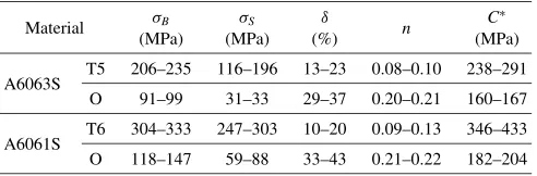
The workpiece materials used in the experiment are aluminum alloys JIS A6063S-O and -T5, and A6061S-O and -T6. Table 1 shows the mechanical properties of the work-pieces. Three types of cross sections are chosen. Type A is a square tube that is hollow. Type B is a square tube containing a reinforcing center rib. Type C is a three-sided, square channel. Figure 1 shows the shapes and dimensions. The widthW0and heightH0are 40 mm. The working lengthLwis
160 mm, or 4 times the heightH0. The workpiece lengthLis
320 mm, and the wall thicknesst0is 3.0, 2.0, 1.5 or 1.0 mm.
In Fig. 1, the symbol indicates the center of the bending radius in each section type. For example, type B1 has a rib which reinforces the two webs; in other words, type B1 has a rib in the circular direction.
2.2 Quasi-uniform bending
Figure 2 shows a schematic representation of the loading system in quasi-uniform bending. The rotational displace-ment of the workpiece is constrained around both thexandy
axes, thus allowing only translational displacement in thex
[image:1.595.305.551.695.776.2]andydirection and rotational displacement in thex-yplane. The workpiece and the loading arm are connected by
Table 1 Mechanical properties of material used.
Material B (MPa)
S
(MPa)
(%) n
C
(MPa)
A6063S T5 206–235 116–196 13–23 0.08–0.10 238–291 O 91–99 31–33 29–37 0.20–0.21 160–167
A6061S T6 304–333 247–303 10–20 0.09–0.13 346–433 O 118–147 59–88 33–43 0.21–0.22 182–204
¼C"n(Test piece: JIS Z 2201 14A)
*This Paper was Originally Published in Japanese in Journal of JSTP46 (2005) 166–170.
chucking parts of steel plate for moment.9) The bending
moment is applied by the loading arm. The cantilever of the loading length LL is 64 times the height H0; thus, the
deviation of the bending moment loaded onto the workpiece is 3%. The concentrated load is measured by a load cell attached to the end of the arm. The radius of the bending die
Rdis 800, 400, 200 or 100 mm, while otherRdvalues of 3200,
1600, 570, 280 or 140 are assumed by extrapolation. The bend degreeH0=Ris the ratio of heightH0to the bend radius
R.Rdis equal to the bend radiusRof the workpiece which is
in contact with the bending die.
2.3 Deformation of cross-section
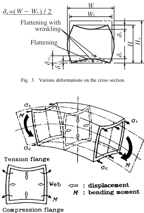
When the bending moment is loaded onto the workpiece, the various deformations of the cross section can be seen in Fig. 3. The parameters T and C represent the concave
distortion of the tension and compression flanges, respec-tively; W represents the convex distortion of the web;CL
andCSrepresent each of the uneven wrinkles.
3. Results and Discussion
3.1 Mechanism of flattening distortion
Figure 4 shows the typical flattening distortion10) of a square tube. Because the flattening is a fundamental deformation, it is already known that the tension and compression flanges will undergo concave distortions, while the webs will suffer a convex distortion. Through the
bending, the flanges of the cross section move in the direction of the neutral axis. Then, the flattening distortion appears as a primary deformation and a decrease of the moment of inertia. The force of the flattening distortion is shown in Fig. 5. If we assume that the neutral axis and the center axis of the cross section on the square tube coincide, and the stress-strain curve is given by¼C"n, then strain"
T
and stressTof the outermost layer of the tension flange can
be expressed as
"T¼H0=ð2Þ ð1Þ
T¼CfH0=ð2Þgn ð2Þ
whereis the radius of the neutral axis,H0is the height of
the square tube,Cis the plastic modulus, andnis the work-hardening exponent. When the circumferential forces on point A and B (on the tension flange with an infinitely small angle d) are represented by PT, the flattening component PTN can be expressed as11,12)
PTN¼t0W0CfH0=ð2Þgnd ð3Þ
where PTN acts vertically along the distance of A and B
(namely,dxT),t0 andW0are constant, andH0is sufficiently
smaller than. Asdecreases, the flattening force increases and the flattening distortion increases.
3.2 Restraining method of flattening distortion
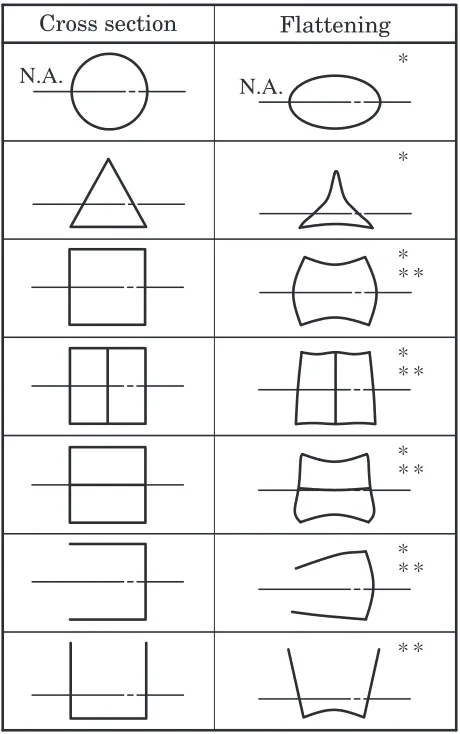
Figure 6 shows the flattening distortion of various types of extruded sections. The use of a mandrel inside the extruded
] ]
0
t
0
=40
=40
W W
W 0
0
t
0
=40
=40
0
Type A
0
t
0
=40
H H H
=40
0
Type B1 Type C1
Type : Cross section
A : [ ]
B1:[ ,B2:[
C1:[ ],C2:[ · ],C3: [ · ]
Thickness t0 (mm)
3.0, 2.0, 1.5, 1.0
1.5
3.0, 2.0, 1.5
Fig. 1 Shapes and dimensions of the workpiece.
=4H
=0
X X
H
B.M.D.
Working length
Loading length
d Die
R
0 w=4H
L
Y
X
0 −3% +3%
Fixed end
Loading arm
Load
0 Workpiece
0
L=64H
L 0
Fig. 2 Loading system and distribution of bending moment.
w
=(
−
0) / 2
δ
CS
δ
CL
δ
0
CT
δδ
0
Flattening with wrinkling
Flattening
W
W
W
H
H
W
Fig. 3 Various deformations on the cross section.
[image:2.595.310.540.71.412.2] [image:2.595.58.281.74.226.2] [image:2.595.56.281.273.411.2]sections may limit the occurrence of the flattening distortion. For triangle sections, a circular mandrel inscribed in a triangle may be selected. In the case of a square tube, a mandrel controlling only each concave distortion of the tension and compression flanges can be selected. In square tube containing a reinforcing rib in the radial direction, the flattening distortion of type B2 is much smaller than that of type A because of the width of the flange of type B2 is half length of the width of the flange of type A. Furthermore, in the channel, type C3, when the concave distortion of the
compression flange can be controlled, at the same time, the outer displacement of the webs is disappear.13)
A mandrel should not collapse from the forces of the flattening components, and so it is necessary to select material and shape that can form to the bend radius. For example, the results show that a laminated elastic mandrel is appropriate. The flexural rigidity of this mandrel is approx-imately 1/10000 of that of the workpiece in the elastic state.4)
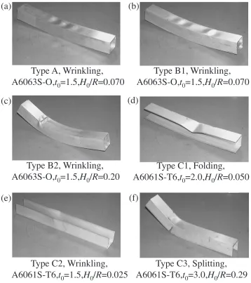
3.3 Wrinkling and splitting
Some typical undesirable phenomena in quasi-uniform bending are shown in Fig. 7. In Fig. 7(a), type A shows wrinkling with concave distortion on the compression flange. The wrinkling is buckling deformation appearing selectively under this working condition. Figures 7(b) and (c) show the typical wrinkling of type B1 and B2. In type B1, the rib in the circumferential direction can restrain the convex distortion of the webs but cannot directly restrain the wrinkling of the compression flange. In type B2, the rib in the radial direction can restrain the concave distortion of the tension and compression flanges. The rib is remarkably effective in restraining the wrinkling of the compression flange, because the pitch of the wrinkling is approximately half compared with type A (without the rib in the radial direction). Figure 7(d) shows the folding in type C1. Because type C1 does not have a web, the folding appears due to the decrease in the moment of inertia according as the increase in the flattening or wrinkling. Figure 7(e) shows the wrinkling in type C2. This specimen does not have the compression flange. Because the neutral axis inclines toward the tension side, the compression region of the web increases. Thus, wrinkling occurs easily in type C2, when the webs are not restrained to move out of its plane. In Fig. 7(f), type C3 shows splitting on the tension side of the webs.
3.4 Deformation mode
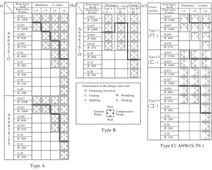
When the extruded sections are subjected to the moment in quasi-uniform bending, undesirable phenomena consist of (a) flattening distortion, (b) wrinkling, (c) folding, (d) necking, and (e) splitting. Figure 8 shows the undesirable phenomena appearing on the cross sections of the extruded sections; the phenomena in this table are labeled D for flattening distortion, W for wrinkling, F for folding, N for necking, and S for splitting.
For the bend degreeH0=R¼0:013{0:10(type A,
A6063S-O, t0¼3:0), only the flattening distortion appears on the
cross section, as shown in Fig. 8(a). For the bend degree
H0=R¼0:14, wrinkling deformation appears on the
com-pression flange, and for the bend degree H0=R¼0:40,
wrinkling deformation appears on the web of the compres-sion side. As the workpiece of the thin thickness is bent, wrinkling deformation easily appears on the compression flange. Thus, the bend degree of the wrinkling limit is approximately fourfold when the thickness of the workpiece is doubled. On the other hand, the bend degree of the wrinkling limit of O is higher than that of A6063S-T5. According to another result,9) the bend degrees of the wrinkling limit and deformation mode of A6061S are similar to those of A6063S.
The result of type A compares with the results of type B1
Flattening components
Tension side
Compression side
Bending stressσand strain ε
(a) (b)
Fig. 5 Mechanism of flattening components.11)(P
T: Circumferential force
of tension side, PC: Circumferential force of compression side,PTN:
Flattening component of tension side, PCN: Flattening component of
compression side)
N.A.
N.A.
Flattening
Cross section
[image:3.595.59.271.72.159.2] [image:3.595.54.284.246.613.2]and type B2, as shown in Fig. 8(b). The bend degree of the wrinkling limit in type A isH0=R¼0:025, and in type B2 it
is H0=R¼0:10. Compared to the bend degree of the
wrinkling limit in type A, type B2 is fourfold because the reinforcing rib in the radial direction efficiently controls the flattening distortion and the wrinkling of the compression flange. In type B1, it is possible to control the concave distortion because the reinforcing rib restrains the webs. However, it does not directly control the flattening distortion. Therefore, type B2 effectively controls the flattening dis-tortion and the wrinkling in the bending of the square tube.
The results of type C in three-directional quasi-uniform bending are shown in Fig. 8(c). In type C, as in type A and type B, as the bend degreeH0=Rincreases, wrinkling appears
on the compression flange first, then on the web. In type C2, there is no compression flange and the bend degree of the wrinkling limit is low. Because type C2 has no compression flange, the neutral axis exists near the side of the tension flange. Thus, the compression strain at the free edge of the web increases. Furthermore, wrinkling can easily appear on the web because it is impossible to restrain the out-of-plane displacement on the web.
In the bending of extruded sections, each structural member of the cross section undergoes the flattening distortion and wrinkling respectively, according to its own position; in other words, the effects extend to other structural members. However, the folding on the whole cross section arises under decreasing of the moment of inertia by the flattening distortion or the wrinkling.
3.5 Relationship between wrinkling and bending mo-ment
Figure 9 shows the relationship between the bend degree
H0=Rand the deformation of the cross section for the bending
moment using type A (t0¼2:0, A6061S-O). As the bend
degreeH0=Rincreases, the convex distortion of the tension
and compression flanges becomes a linear and stable deformation. Wrinkling appears from approximately the bend degreeH0=R¼0:07. It is easy to distinguishCL and
CS(the uneven wrinkles with flattening distortion, as shown
in Fig. 3). The wrinkling that appears with the increase in the bend degree H0=R is buckling deformation. Because the
concave distortion of tensionTis defined by the position of
the neutral axis, the influence of the wrinkling of the
Type A, Wrinkling,
A6063S-O,
t
0=1.5,
H
0/
R
=0.070
Type B1, Wrinkling,
A6063S-O,
t
0=1.5,
H
0/
R
=0.070
Type B2, Wrinkling,
A6063S-O,
t
0=1.5,
H
0/
R
=0.20
Type C1, Folding,
A6061S-T6,
t
0=2.0,
H
0/
R
=0.050
Type C2, Wrinkling,
A6061S-T6,
t
0=1.5,
H
0/
R
=0.025
Type C3, Splitting,
A6061S-T6,
t
0=3.0,
H
0/
R
=0.29
(a)
(b)
(c)
(d)
(e)
(f)
[image:4.595.119.477.74.477.2]compression flange is negligible. In regard to the bending moment, the buckling limit does not agree with the maximum bending moment because the influence of work-hardening in bending precedes that of the wrinkling in the compression flange.
4. Conclusions
(1) Undesirable deformations in the bending process of extruded sections consist of (a) flattening distortion, (b) wrinkling, (c) folding, (d) necking and (e) splitting. The flattening distortion as primary deformation appears through the bending operation. The wrinkling and the folding appear as buckling deformation with an increase in the bend degree H0=R. The necking and
the splitting depend on the ductility of the material. (2) On the flattening distortion, each element of the cross
section of the extruded section moves in the direction of the neutral axis because of the flattening component. The flattening forces increase as the area becomes distant from the neutral axis.
(3) Though the form of flattening distortion differs depend-ing on the shape of the cross section of the extruded section, the mechanism for the deformation is the same. When the forms of the flattening distortions are clarified by FEM simulation, it is possible to estimate the optimal shape of the mandrel and the effects of the working conditions.
(4) The wrinkling never appears at the beginning of the bending operation because the progress in bending causes the buckling (wrinkling). In hollow square tube, the bend degree of the wrinkling limit is approximately fourfold when the thickness of the workpiece is doubled. 3.0 2.0 1.5 (b) (a) :570 0.070 0.070 :570 0.29 0.20 0.14 0.10 0.40 0.20 0.10 0.14 0 Thickness (mm) DW DW DD DD DD DD DD DD DD DD DD DD DD WW DW DW DD DD DD DD DD WW DW DD DD WW DW DD DD WW :200 :280 :400 :800 0.050 :1600 0.025 :3200 0.013 3.0 DW DW DW DW DD DD DD DD DD DD DD DD DD DD DD DD DD WW 2.0 DW DW DW D DD D DD DD DD DD DD DD WW 1.5 DW DW DD DD DD DD D D WW 1.0 DW DD DD WW :100 :140 :200 :280 :400 :800 0.050 :1600 0.025 :3200 R R R R R R R R R R R R R R R R 0.013 Bend degree Bend radius R(mm) R H Type A
Deformation of the flanges and webs
Web flange Tension flange Compression Web
N : Necking
W : Wrinkling
S : Splitting
F : Folding
D : Flattening distortion 0.20 0.14 0.10 W DW DW DW W D W D W D WW WW D D D D D D DD DD DD DD DD DD DD DD DD DD DD DD D DD DD DD DD DD WW Type B2 Type B1 [ · ] Type A
Thickness t0=1.5(mm)
:200 :280 :400 :570 0.070 :800 0.050 :1600 0.025 :3200 R R R R R R R 0.013 Bend radius
R (mm) Bend degree
0 H R/
Type B D 0.29 0.20 0.14 0.10 W W W W W D D D D D DD D DD D DD D D D DD D DD D D D DD D DD D Type C3 Type C2 Type C1 [ · ] section Cross– W S S W N N W N N W W W W W W W W :140 :200 :280 :400 :570 0.070 :800 0.050 :1600 0.025 :3200 0.013 :1600 0.025 :3200 0.013 W W D W W W W D D D D D D D D D W W W DD D DD DD F F F F F F DD D DD D DD 0 Thickness (mm) :570 0.070 :800 0.050 :1600 0.025 :3200 0.013 R R R R R R R R R R R R R R Bend radius
R (mm) Bend degree
H R0/
Type C( A6061S-T6 )
(c) t
0/ t
[ · ] [ · ] [ · ] [ · ] A 6 0 6 3 S O A 6 0 6 3 S O A 6 0 6 3 S T 5
Fig. 8 Deformation mode of various extruded sections under quasi-uniform bending moment.
0
M/ t
T
δ
CS 0δ
CLH
0H
H
T
δ
0Deformation of compression flange CL
H
0,δ
CSH
0:H
δ
:Deformation of tension flange
Buckling limit
Bend degree
H R
0/
0 T
δ
0 0.15 0.05 0.10Bending moment
M
/
t
0(kN·m·m
)
–110–2 10–1
150 0 50 100 200
δ
CL,
δ
0 CS 0δ
0H
H
H
,
[image:5.595.89.511.69.409.2] [image:5.595.58.283.450.647.2](5) In square tube containing a reinforcing rib in the radial direction, the reinforcing rib prevents the flattening distortion and wrinkling. The bend degree of working limit in this type is approximately fourfold compared to that in hollow square tube.
(6) In channel type sections, the three-directional bending differs according to the position of the neutral axis. In channel without a compression flange, the bend degree of the wrinkling limit is low. In this type, the neutral axis exists near the side of the tension flange. Thus, the compression strain of the web increases. Furthermore, wrinkling can easily appear on the webs, when the working condition of the out-of-plane displacement on the web is free. The bend degree of the wrinkling limit in channel without tension flange is approximately fourfold compared to types the other two types of channel section.
Acknowledgments
The authors would like to express their thanks to the Committee of Forming Research of the Extruded Sections at the Japan Institute of Light Metals for providing the extruded sections, and also to the AMADA Foundation for Metal Work Technology for their financial aid.
REFERENCES
1) M. Ueda, K. Ueno and M. Kobayashi: Journal of JSTP25(1984) 793– 798.
2) O. Hasegawa and N. Nisimura: J. JILM46(1996) 243–248. 3) The Committee of Forming Research of the Extruded Sections: The
Report of Branch Research Committees, No. 36 (JILM, 1999) 15–21. 4) N. Utsumi and S. Sakaki: J. Materals Processing Technology 123
(2002) 264–269.
5) J. Endo and T. Murota: Journal of JSTP23(1982) 708–713. 6) J. Endo and T. Murota: Journal of JSTP27(1986) 201–207. 7) Y. Yokouchi and Y. Mune: Proc. 1995 Japanese Spring Conference for
the Technology of Plasticity, (JSTP, 1995) 265–266. 8) F. J. Fuchs, Jr.: Bell. Syst. Tech. J.38(1959) 1457–1484.
9) The Committee of Forming Research of the Extruded Sections: The Report of Branch Research Committees, No. 32 (JILM, 1996) 19–27. 10) S. Sakaki, T. Toin and T. Harasima: Journal of JSTP36(1995) 719–
724.
11) S. Sakaki: Proc. Tokyo Metropolitan Institute of Technology 15 (Tokyo Metropolitan Institute of Technology, 2001) 67–72. 12) S. Sakaki and N. Utsumi: Proc. 7th Inter. Conf. on Advanced
Technology of Plasticity, ed. by M. Kiuch, H. Nishimura, J. Yanagimoto, (Japan Society for Technology of Plasticity, 2002) Vol. 2, 1763–1768.