Mechanical Properties of Fe–Mn–Si Based SMA and the Application
Akikazu Sato
1;*, Hiroshi Kubo
2and Tadakatsu Maruyama
3 1Tokyo Institute of Technology, Tokyo 152-8552, Japan2Kanto Polytechnic College, Oyama 323-0813, Japan 3
Awaji Sangyo K.K., Tokyo 101-0052, Japan
The SME (shape memory effect) in an Fe–Mn–Si based SMA is governed by motion of Shockley partial dislocations which carry the fcc$hcp phase transformations. The degree of SME is determined by preservation of the partial dislocations whereas the strength is determined by the internal stress opposing against the dislocation motion. The increase in the internal stress tends to induce dislocation reactions which ruin the preservation of the Shockley partials and hence to decrease the degree of SME. Nevertheless, usage of this SMA for construction of a large structural product has recently gained much attention even with sacrifice in the degree of SME. Upon application of this SMA in such a field, the optimum condition has to be searched both in the mechanical properties of the SMA itself and the type of the usage in the sense of deformation mode such as elongation, contraction, bending, twisting and so on. In this paper, the dislocation motion responsible for a good SME with high strength will be discussed on the ground of the basic knowledge of the dislocation generation, the motion and the reactions.
(Received September 20, 2005; Accepted December 15, 2005; Published March 15, 2006)
Keywords: shape memory effect, iron–manganese–silicon, martensite, Shockley partial, dislocation
1. Introduction
It is more than 20 years, since a good SME was found in an Fe–Mn–Si alloy in the early 1980s.1–3) Originally the
research was started to examine the !0 martensitic transformation using the Fe–16 mass% Cr–14 mass% Ni stainless steel and one way type of the Schmidt law was confirmed for theh112if111gshear.4,5)Starting with the base composition of Fe–(30–32) mass% Mn–6 mass% Si,3,6,7)the investigations have been focused on anti-corrosion,7)training
effect,7–9) internal friction,10) cyclic-deformation11,12) and
strengthening.13–20)The hybrid types of the Fe–Mn–Si based
shape memory alloys (SMA) have been developed and some of the representative compositions are listed in Table 1.
Among them the Fe–28%Mn–6%Si–5%Cr (mass%) SMA has been paid much attention for the use in several constitution components.7,17)The SMA developed by
intro-duction of the precipitates such as NbC13)or VN18)is another
candidate for the future use. It has also become apparent in the recent studies that the Fe–Mn–Si based SMA can be strengthened further by beating and heating treatments due to introduction of the non-deformable domains called Mn typephase.19,20)
From the industrial point of view, it is attractive that this SMA is mainly composed of the low cost elements of Fe, Mn and Si. Moreover, the Fe–Mn–Si based SMA can be manufactured by the readily available plants for the com-mercial iron and stainless steels. Nevertheless, the cost may not be lowered in practice unless the amount of the needs reaches that of the usual steels. In this sense application to the large construction components is beneficial. The present report mainly focuses on the possibility of such usages. The particular attention will be paid for the shape recovery strength and the large damping effect governed by motion of the Shockley partial dislocations. Concerning the latter property, Fe–Mn and Fe–Mn–Cr alloys21–24) are reported to
show a high damping effect due to existence of"("0) phase. The shear deformation governed by motion of the Shockley partial dislocations plays an important role in the high-manganese (15–25 mass%) steels. Because of the high strength with good ductility manifested by these alloys, they are called ‘‘Twinning Induced Plasticity (TWIP)’’ and/or ‘‘Transformation Induced Plasticity (TRIP)’’ steels24) but
without SME. Although the knowledge of the SME itself is of direct importance in planning the application, a high work-ability is sometimes required and is achieved by improve-ment of the ductility and by cultivation of the designing for applications.
Especially, the designing and manufacturing for the practical use of the SMA play the decisive role, which is related to the total preparation processes. The actual steps to be cleared before the use are summarized in Table 2. In the present paper, special interest will be put on the designing for application of the SMA with knowledge of the basic properties governed by motion of the Shockley partials. The free energy change associated with the $"0 phase transformation comes into all the steps described in Table 2, and is the direct importance in the step 4 to obtain a good SME.
2. Basic Properties
2.1 Directionality in theh112if111gshear
[image:1.595.306.548.331.431.2]One of the characteristic features in the Fe–Mn–Si based
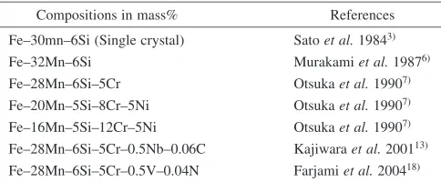
Table 1 Representative FeMnSi based SMA developed in the past.
Compositions in mass% References
Fe–30mn–6Si (Single crystal) Satoet al.19843Þ
Fe–32Mn–6Si Murakamiet al.19876Þ
Fe–28Mn–6Si–5Cr Otsukaet al.19907Þ
Fe–20Mn–5Si–8Cr–5Ni Otsukaet al.19907Þ
Fe–16Mn–5Si–12Cr–5Ni Otsukaet al.19907Þ
Fe–28Mn–6Si–5Cr–0.5Nb–0.06C Kajiwaraet al.200113Þ
Fe–28Mn–6Si–5Cr–0.5V–0.04N Farjamiet al.200418Þ
*Emeritus Professor, Tokyo Institute of Technology; Corresponding author, E-mail: [email protected]
Special Issue on Shape Memory Alloys and Their Applications
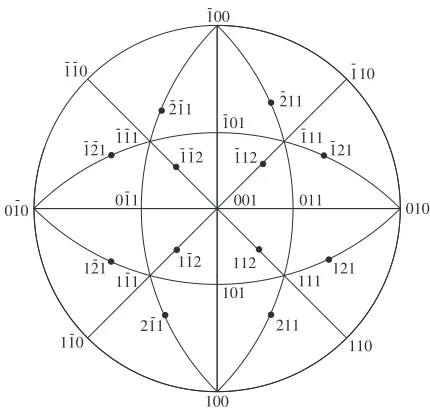
SMA may be the one way directionality in the h112i shear displacements confirmed in a stainless steel.4)For example, the operative shear systems are different in the compression and tension, causing the stress axis to rotate towards theh111i
direction in both cases. The reason is explained by use of a stereographic projection shown in Fig. 1. The judgment of the sense of the shear direction can be made by finding location of theh001i andh110idirections in the figure. For example, when a stress axis is located along the½0110 -[101]-[010] major circle, the [121]ð1111Þ shear will operate by tensile stress in the region containing the [101] along the
½1111-[121] and by compressive stress in the region contain-ing the [010]. Similarly the sense of the stress can be judged for any shear systems and stress axes. To start with, let us consider a stress axis located inside the standard triangle [001]-[101]-[111] in the figure. The operative shear systems with the largest Schmidt factors are the [121]ð1111Þin tension and the ½11112(111) in compression. Operation of the [121]ð1111Þshear in tension will rotate the stress axis towards the [121] displacement direction and eventually towards the [111] direction by the simultaneous operation of the
[211]ð1111Þ shear after hitting the [001]-[111] zone. On the other hand, operation of the½11112(111) shear in compression will rotate the stress axis towards the (111) shear plane normal coincident with the above mentioned rotation in the case of the tensile deformation. Interestingly, the similar arguments can be made for all of the 6 triangles surrounding the [111] direction. Although the rotation is restricted by incompatibility in poly-crystals, the general tendency of the stress axis rotation towards theh111idirection in both of the tension and compression is a unique property to be remembered in the practical application of the steels, involving the h112i type of the shear displacements as in the present SMA.
2.2 Property of the Shockley partials contributing to the
SME
The SME is totally governed by the $"0 phase transformation due to the free energy change associated with motion of the Shockley partial dislocations. As it is well known, there is a limitation in the shape deformation recoverable by the phase transformation. The elongation due to the shear deformation depends on the shear (slip) plane geometry and it can be estimated according to Fig. 2 as follows. Suppose that a tensile stress is applied along the broken line inclined by 0 in the beginning and after
elongation. The tensile strain resulting from the sheared angleinduced by motion of the Shockley partials is given by
"¼ ðll0Þ=l0
¼
ffiffiffiffiffiffiffiffiffiffiffiffiffiffiffiffiffiffiffiffiffiffiffiffiffiffiffiffiffiffiffiffiffiffiffiffiffiffiffiffi
1þ ðtan0þtanÞ2 q
= ffiffiffiffiffiffiffiffiffiffiffiffiffiffiffiffiffiffiffiffiffiffi1þtan2 0 p
1; ð1Þ
where l0 and l are the specimen length before and after
elongation. Since the Schmidt factor must be reasonably large for the shear system to operate, the plausible value of
0 may be in the neighborhood of 45 and the maximum
shear attainable by the !"0 transformation is given by ¼tan1ð1=2pffiffiffi2Þ ¼19:6. Just for curiosity, the assignment of0 ¼10, 30, 45, 60and 80gives"¼0:12, 0.18, 0.19,
[image:2.595.47.549.84.255.2]0.14 and 0.06, respectively. Thus, contribution of the shear deformation to the elongation does not severely depend on the slip plane geometry, especially in the range of the large Schmidt factor, say for0¼30{60.
Table 2 Summary of the processes needed for use of the FeMnSi based SMA.
Process
steps Contents of the process Practical treatments
Shaping (step 1)
Memorization of the designed shape with the(fcc) phase
Heating up to 1223 K under a constraint after shaping at room temperature or shaping directly above 1223 K
Training (step 2)
Improvement of the SME in the magnitude as well as in the recovery strength
Heating up to 873 K after straining by 5–10% (The first training cycle is most effective.)
Pre-Strain (step 3)
Introduction of the"0phase
(hcp) after memorization of the shape
Deformation at room temperature by tension, compression, bending, twisting, their combination and other
Recovery of Shape (step 4)
Recovery of the shape by"0!
reverse transformation
Hearting up to 623 K (Care must be exercised in controlling the heating rate and the temperature distribution.)
100 010 001 011 111 101 111 -110 10 -1 -100 -110
111
-111 -011 -110 -010 -121 -211
-112- 112 121
211
-112 121
-211
-121- - 112
-211
-101
[image:2.595.60.275.286.493.2]In the actual measurements, however, the recoverable strain is only 0.04–0.07 in elongation. The tensile property must be affected strongly by operation of the multiple shear systems, especially in the usual policrystals. This is possibly due to exhaustion of the mobile Shockley partials, by which the recoverable strain is determined. Hence, the training effect some times plays a decisive role in the SME by generation of the Shockley partials8) and actually used in
application.17) Related to the problem of the dislocation
sources and their preservation, there are important factors controlling the SME properties such as intersection of one shear system with others, generation or stopping of the partials at grain boundaries and precipitates, retardation of the motion by Cottrell atmospheres and non-deformable obstacles, and so on. The above factors contribute either to improve or to retard the SME properties in the recovery strain or in the strength.
Although it is important to know the behavior of the basic properties individually, the characteristic behavior of the SMA in the practical use is determined by total combination of the basic properties. Therefore, development of a good SMA for the aimed use depends largely on the trials and errors. The important attitude may be the correct recognition of the factors controlling the SME and the strength on the ground of the basic knowledge and its use in the trials and errors.
2.3 Workability
The every step of the processes listed in Table 2 must be scheduled according to the basic properties of the SMA linked to the choice of the composition given in Table 1. In the step 1, there are various choices in the way of shaping. The starting point may be the shape of the ingot. It is obviously beneficial to minimize the machining or the additional work for shaping by preparation of the proper
ingot. In this sense, for example, preparation of the pipes by centrifugal casting is one possibility in minimizing the work needed for shaping of the Fe–Mn–Si based SMA25) and
actually applied in the tunnel construction with success.17)
The alternative method is to make a pipe by bending of a sheet. When large deformation is needed, the workability becomes important. It is fortunate that this SMA is quite similar to the TRIP/TWIP steels in the sense that deforma-tion is governed by Shockley partials as mendeforma-tioned in Introduction. Namely, either the"0phase or thephase twins formed in advance by motion of the Shockley partials can be deformed further by non-basal slips or by twinning in the"0 phase and by the {111} slips in the phase twins. In the heavy deformation the 0 (bcc) phase is also introduced at intersections of the shear bands.26–29) It is called ‘‘window effect’’,27)implicitly meaning the good deformability. Thus, workability of the present SMA is well guaranteed by motion of the Shockley partials at room temperature.
However, it is some times necessary to prevent the SMA from breaking when heavy deformation is needed. Super-position of either a hydrostatic pressure or a proper constraint is effective, although the shape deformation is governed by various types of shear displacements involved in the!"0, "0!0and !0transformations, and twinning in the, "0and0phases in addition to usual slips as mentioned above. Then, annealing above 1223 K under a constraint will bring the"0and0phases back to thephase by holding the desired shape to be memorized. The alternative way to memorize the aimed shape is to deform it directly above 1223 K, although this type of shape deformation is limited to some extent by the workability at such a high temperature.
3. Characteristic Properties of the Fe–Mn–Si Based
SMA
3.1 Recovery strength
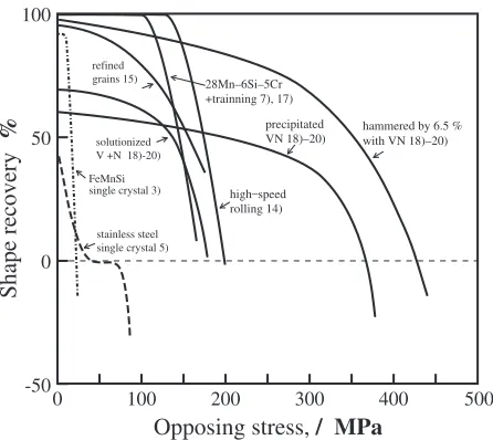
There are various ways to measure the recovery strength, which is the most important property in its application, especially in the heavy duty construction. It is fortunate that the mechanical properties can be examined by using small samples. This is because the strength is totally determined by dislocation motion, which takes place in units of the Burgers vectors. The information obtained by either a small or a large sample can be compared in terms of the normalized intensive parameter of the internal and external stresses . Figure 3 shows the summary of the recovery strength against the opposing stress measured by using small samples for various kinds of the Fe–Mn–Si based SMA3,7,14,15,17–20)including the
results of the stainless steel single crystals.5)It is noteworthy
that the strength changes remarkably depending on the composition and treatment made prior to the step 4 in Table 2. Interestingly, the SMA pre-annealed for precipita-tion of the VN prior to the hammering and heating exhibited a good SME without training as shown in Fig. 3. The VN precipitates decorated with dislocations by that treatment is judged to be the origin of the good SME and the good ductility according to the stress strain curves and the microstructures as shown elsewhere.19)
Thus, the origin of the changes in the SME properties of the present SMA can be attributed totally to the motion of the
shear plane
0 h
l0
l
[image:3.595.66.269.68.326.2]Shockley partial dislocations. The recovery strength is equivalent to the sum of the frictional and internal stresses opposing against the partial dislocation motion. The larger the opposing stress is, the larger is the chemical force needed for the"0! reverse transformation, leading to the higher recovery strength as shown in Fig. 3. The chemical driving force comes from the free energy change associated with the motion of the Shockley partial dislocations, which carry the
$"0transformation. It increases asTdeviates from theT0,
the temperature at which the free energy becomes equal for two phases.30)Therefore, the magnitude of the recovery force
increases with the temperature (T) of the shape recovery ("0!). Consequently, the later the recovery stage is, the larger the recovery strength is expected, owing to the distribution in the internal stress. The degree of distribution in the internal stress may be inquired in the temperature dependence curve of the recovery strain.8)
In the above experiments, the annealing for the recovery was made by a creep type machine under a constant load and the recovery strain was measured after unloading. On the other hand, another common procedure in detecting the dimensional change is to utilize the elastic strain induced by the shape change associated with the $"0transformation under a constraint imposed during heating and cooling. An example is shown in Fig. 4.31)The vertical axis shows the
stress induced by the change in the specimen length during the heating and cooling cycle. Training effect is also noted in the figure by comparison of the broken and solid lines. It is apparent that the training effect lowers the starting temper-ature of the shape recovery. This fact implies the increase in the number of the Shockley partial dislocations as analyzed in the earlier study by using single crystals.8)The increase in
the strength from a to b can be attributed to the shrinkage of the specimen due to the reverse transformation by the reverse motion of the Shockley partials. The further increase of the stress upon cooling to c after saturation in the stress at 603 K may come from the difference in the thermal expansion between the tensile jig and the specimen. Then, the stress decreases to a minimum level at d by the further cooling. The
stress level at room temperature corresponds to the binding force expected, for example, when it is used as a pipe joint at ambient temperature. Another interesting observation is the increase in the subzero temperature region after passing the minimum upon further cooling to f. This phenomenon may be attributed to the !"0 transformation expected against the imposed stress below the Ms (martensite starting temper-ature). The occurrence of such transformation against the stress implies reversible motion of the Shockley partial dislocations by the temperature cycle and hence the possi-bility of the two-way SME, although the magnitude of the shape memory strain may be considerably smaller than that due to the"0phase induced by the pre-straining.
3.2 Designing of the SME for application
3.2.1 Tubes
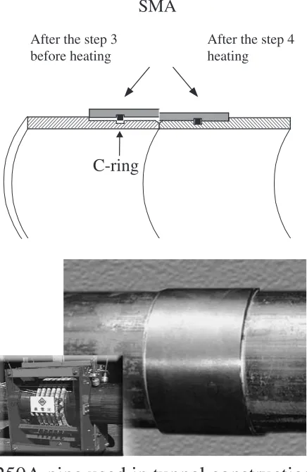
The simplest type of application is to use recovery strength in the elongation. The connecting force generated at the pipe joint belongs to this category in the sense it utilizes the contraction after the elongation around the pipe joint. In the actual designing, however, the joining action must be guaranteed for various environmental conditions such as vibration, heating, cooling and various types of mechanical disturbances. On of the reliable designs is to use a C shaped ring as shown in Fig. 5. This design was used in the tunnel construction with success.17)Upon designing the components for heavy duty, gradual change in the shape by cycling loading must be cautioned in advance. The C ring is effective in this point, since the pulling force acting on the connected pipes is mainly sustained by the C ring(s). The joint must be safe even if a minor change occurs in the tightening force at the SMA by some reason. Thus, designing plays a key role upon application. For example, when a smaller rod of 24 mm in diameter was joined without the C ring, the lack of recoverable strain caused quite different results depending on the materials gripped by the SMA. The connection became completely loose in the case of an Al rod whereas a stainless pipe of the same size could be connected tightly by the same joint. The cause is found to come from the difference in the thermal expansion coefficient between the SMA and the Al.31)
Another interesting property of a tube may be that it can be machined into any shape such as with various types of open
-200 -100 0 100 200 300 300
100 200 400
before training after training
a
b1
c1
d1
e
a1
b c
d f
Temperature, / oC
Stress /MPa
Fig. 4 Variation in the stresss induced by the shape recovery undr a constraint imposed during heating and cooling after deformation at step 3 in Table 2.
0 100 200 300 400 500
-50 0 50 100
Opposing stress,
/ MPa
Shape recovery
%
refined grains 15)
solutionized V +N 18)-20)
single crystal 3) FeMnSi
stainless steel single crystal 5)
high–speed rolling 14)
precipitated VN 18)–20)
hammered by 6.5 % with VN 18)–20) 28Mn–6Si–5Cr
+trainning 7), 17)
[image:4.595.58.281.72.271.2] [image:4.595.314.540.72.213.2]holes. The extreme case would be a basket made of strings used to rap oranges. In this case, bending takes part into the tightening action. By suitable combination of the bending and the elongation, the recoverable strain must increase notably with sacrifice of the strength. The difference in the dislocation distributions contributing to the bending and the elongation is compared by drawing giant dislocations to visualize the difference schematically in Fig. 6. It is apparent that possibility of dislocation annihilation is higher in the elongation mode in (b). Although the shear plane of the individual dislocation is inclined with respect to the horizontal axis, the higher tendency of the dislocation pairing of the opposite signs in the elongation mode is analogous to the representative drawing shown in Figure 6. Thus, combi-nation of the different mode of deformation may be advanta-geous for certain purposes in the practical use, especially when the full strength of the present SMA is not required.
3.2.2 Strait bars
Another example of an application to a heavy duty component is the use of a joint in connecting rails to close the ends tightly by the pulling force. The SMA bars prepared for the purpose are shown in Fig. 7. The principle of the use is simple and may not need explanation. Nevertheless, it is important to note that the force generated by contraction of the SMA is totally supported by the bolts both at contact with the rail and the SMA. Since direction of the force acting on
the bolt is opposite in the rail and the SMA sides, the bolt must be strong enough against the shearing not to be bent. Another point is that the force generated by contraction of the
(a)
(b)
Fig. 6 Simplified difference in the dislocation distribution between bending and elongation. The Shockley partials of the opposite signes are expected to be preserved more in the bending.
SMA bars
before heating
after heating
SMA bars
Fig. 7 The straight bars used for the rail joint.
SMA
After the step 3 before heating
After the step 4 heating
C-ring
250A pipe used in tunnel construction
[image:5.595.317.523.75.254.2] [image:5.595.59.277.76.411.2] [image:5.595.313.541.314.712.2]SMA is delivered to compress the rail at the end side and to elongate at the long rail side. In order to avoid compression at the long rail side the SMA may have to be installed when it is shortest. Then, the decrease in the tensile stress at the long rail side due to elongation is compensated by the increase in the compressive stress at the end side where the serious bending due to compression is not expected. The present SMA may similarly be applied to support some components or to become the component itself forming a structural assembly, by the elastic strain arising from the reverse transformation.
3.2.3 Wires
Contraction of a straight wire may be utilized in the similar sense as the rail joint after stretching at the step 3 and heating at step 4 in Table 2. The tensile stress generated by heating the SMA after setting it in some system may be useful in holding the assembly free from disturbance or the SMA itself may be used to be held straight under the tensile stress caused by the reverse transformation after the step 4. Especially a high tensile stress is expected in the SMA with VN precipitates and phase as shown in Fig. 3. There is, however, limitation in the tensile strain.
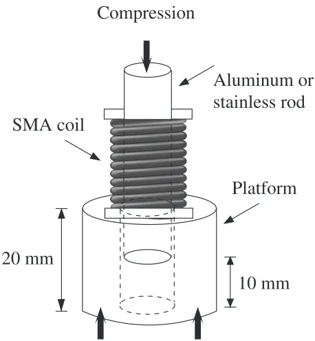
[image:6.595.321.534.74.215.2]In order to obtain the larger shape change, bending is superior to elongation as discussed by referring Fig. 6 in 3.2.1. If the recoverable shape strain is compared in the diameter, a coil is superior to a solid tube substantially, although the gripping strength is much smaller compared to the tube. The resistance against slip of the SMA was tested by pushing the gripped rod as shown in Fig. 8.33)The resisting force was found to increase continuously with displacement in the case of Al rod whereas it saturated at a substantially low level in the case of stainless steel rod as shown in Fig. 9.33) The condition for preparation of the SMA was
exactly same for the two cases in all the steps described in
Table 2. Increase in the gripping force in Al apparently comes from the scratching of Al as shown in Fig. 10.33)
Combination of the strong SMA and the weak Al is important in this case so that the Al in contact with the SMA was scratched to fill out the gaps between the coil and the Al as pushed as shown in Fig. 10(b). On the other hand, the stainless steel having the similar strength as the SMA was scratched very little as shown in Fig. 10(c).
The results of the gripping force is opposite in the two cases of the Al mentioned here and in 3.2.1. That is, in the case of a rather small solid tube-joint (25mm), the large thermal expansion coefficient of the Al released the gripping force completely upon cooling after the heat treatment.31)
The opposite results obtained for the tube and the coil in the case of Al clearly indicate the importance of the additional factor in practice. Thus, combination of the bending and elongation mentioned in Fig. 6 is revealed to be important in coupling the soft materials, especially when the present SMA is applied for joining a small object. The control of the combination of the bending and elongation along the tangential direction of the coil can be made by designing a proper jig for the pre-straining in the step 3 in Table 2. The results shown in Figs. 8–10 are the ones obtained under the best condition for both of the Al and stainless steel in the gripping ability. Further more, the strength was confirmed to increase almost linearly with the number of the turns of the coil as naturally expected. Gathering the over all results, it is anticipated that a joint may be used for soft materials such as aluminum, woods and plastics by proper combination of the bending to increase the recoverable strain with sacrifice in the recovery strength.
3.2.4 Plates
The most popular shape of the steels supplied by the industry is a plate with variety of thickness and width. It is attempted here to testify the workability in bending to form a tube and in twisting to form a wire. The tube was made by the specially designed and hand made dices to have overlapped portion so that the strength and the shape deformation can be controlled at the step 3 by use of a specially designed tool for pre-straining. Another trials made in this study is the twisting of a long plate. In this test, a twisted wire was made by using a drilling apparatus. Heating of the wire was easy by sending
Compression
Aluminum or
stainless rod
Platform
SMA coil
20 mm
10 mm
Fig. 8 A schematic drawing of a set up for measuring the resistance against slip of a coil. The resistance depended strongly on the material of the rod as described in the text.
Lord, /kg
300
250
200
150
100
50
0
Displacement, /mm Al rod
Steel rod
[image:6.595.54.283.500.748.2]proper current and the temperature could be estimated from the wave length of the light emitted from the wire. In both of the tests made here, the Fe–28%Mn–6%Si–5%Cr plates of 0.3 mm in thickness was used by cutting it into the desired sizes using a shear cutter.
Figure 11 shows an example of the overlapped tube made by using the special dices. Most of the work corresponding to
the step 1 was done at room temperature with intermittent annealing at1073K. The final annealing under constraint to memorize the shape was also made at 1073K. The overlapped area determines the contribution of the bending and elongation conducted later at the step 3 in Table 2 and hence it affects the recovery strain as well as the recovery strength. Since the overlapped area can be controlled easily by choosing the initial width of the plates, it is easy to control the recovery strength, naturally at a lower level compared with the solid tube joint. In using it for various applications, however, it must be reminded that an designing must be testified for the safety as actually employed in use of the SMA in the tunnel construction.17)
The final example is the twisted wire, in which the Shockley partials will be introduced most effectively in shear mode, increasing from the center towards the edges. Some examples of the twisted wires are shown in Fig. 12. They were prepared from the SMA with the width of 1, 3 and 5 mm and 150 mm in the length and were twisted to the fracture in the case of the 1 and 3 mm width. Apparently, the pitch in the cyclic patterns varied nearly proportional the plate width as found in Fig. 12. In order to visualize the shear displacements involved in the twisting, the short segment of a twisted wire is depicted by a schematic drawing in Fig. 13. In the figure, the
(a)
(b)
(c)
Al
stainless
steel
[image:7.595.55.284.71.639.2]Al
[image:7.595.313.541.71.233.2]Fig. 10 Observation of the scratches appeared after pulling against the gripping force. Comparison of the figures (a) and (c) with the scratched Al at the top in (b) clearly indicates that the large resistance (gripping force) was induced by accumulation of the Al in the gaps of the SMA coil.
[image:7.595.312.540.286.440.2]Fig. 11 Overlapped coils made of the SMA plates with the thickness of 0.3 mm.
shear strain is shown to increase towards the outer edge. Here, the maximum value is assigned to take nearly 1, since the angle of the cyclic ripples at the nodes is approximately 45in Fig. 12. Especially, the angle is nearly same for the 1 and 3 mm plates twisted to fracture, whereas it is somewhat smaller for the plate of 5 mm as seen in the partially winded tube shown at the top. Interestingly, the angle is 20, which corresponds to the maximum strain attainable by shear deformation carried by motion of the Shockley partials in the
!"0transformation as mentioned in 2.2.
The limitation in the twisted angle may be related to the sudden increase in the work hardening due to the limitation in the!"0transformation. This is may be a unique property in causing the transition in the mode of deformation from twisting to winding as noted in the center portion of the wire at the top in Fig. 12. The transition from twisting to winding started at the center portion and expanded to the left without the further twisting at the right. For this reason, it is apparent that the Shockley partials were introduced locally in different manner from the twisting at the starting point in the wire. The clear difference in the twisting and winding is that the partials must be introduced homogeneously across the width in the winding. In contrast, the shear direction must be opposite and symmetrical with respect to the non-deformed zone across the twisted width as shown in Fig. 13. The triggering action may be the shift in the non-deformed region causing redistribution of the Shockley partials across the width at the limiting strain in the twisting. Once the switching occurs at some place, it is natural that the winding propagates towards one direction as observed in the figure. The winding of a plate may be another way of making a coil of different structure just like a ‘‘KOYORI straw’’.
Turning back our attention to the twisted wire, it may be used for various purposes by giving the proper pre-strain at the step 3. For example, rewinding or unwinding to generate rotation motion of the wire upon the reverse transformation. In the case of the wire of 3 mm shown at the center in Fig. 12, the recovery strain was 30% as counted by the change in the number of the ripples. Another way of the usage is possible by coming back to the step 1 for the further working to memorize a coil shape composed of the twisted wire. Then, the edge along the twisted wire should become effective in gripping a soft material in the similar manner as in the case of the SMA coil used for Al (Figs. 9 and 10). Furthermore, in the coil made of the twisted wire, the twisting action can be
superimposed to increase the resistance caused by scratching such as shown in Fig. 9. It is true in principle that the shear deformation carried by the Shockley partials can be utilized effectively when bending and/or twisting is coupled with elongation or contraction.
Upon practical application, therefore, the surface condition in contact with the structural materials in use may play an important role as observed in Fig. 10. It has been known that the surface is altered severely by the atmosphere of the heat treatments both in steps 1 and 4. Moreover, the compositional change has been noted below the surface to affect the physical and chemical properties of the SMA as reported in the recent studies.34)The further study is apparently needed on this account since the SMA must be heated in contact with some other materials.
4. Final Remarks
In the present paper, the subjects were restricted to those related to the interest of the present authors. Although the explanations were not given in details it is hoped that a reader may find the further information in the literatures referred mostly in conjunction with the Fe–Mn–Si based SME. The major purpose was to introduce the current status of its application to the heavy duty components, which may be unique to the present SMA, being entirely different from the other popular SMA. In order to elucidate the unique properties with its application to some heavy duty compo-nents in mind, however, the experiments in the laboratory scale by using a small sample is yet important. Since the law of the similarity is normally applicable in the field of metallurgy, the results obtained here for the bending and twisting of the FeMnSi based SMA must be of any help in the heavy duty application. It is just a matter of its practice in the large scale, for which the iron and steel industries will have the sufficient historical background in both theory and practice. It is hoped that the present SMA is applied widely to improve the quality of the living standard, especially in the safety against the natural hazards.
REFERENCES
1) A. Sato, E. Chishima, K. Soma and T. Mori: Acta Met.30(1982) 1177– 1183.
2) A. Sato, K. Soma and T. Mori: Acta Met.30(1982) 1901–1907. 3) A. Sato, E. Chishima, Y. Yamaji and T. Mori: Acta Met.32(1984)
539–547.
4) A. Sato, Y. Sunaga and T. Mori: Acta Met.25(1977) 627–634. 5) A. Sato, H. Kasuga and T. Mori: Proc. Int. Conf. Martensitic
Transformation6(1979) 183–187.
6) M. Murakami, H. Otsuka, H. G. Suzuki and S. Matsuda: Proc. of ICOMAT-86, (JIM, 1987) pp. 985–990.
7) H. Otsuka, H. Yamada, T. Maruyama, H. Tanahashi, S. Matsuda and M. Murakami: ISIJ International30(1990) 674–679.
8) Y. Watanabe, Y. Mori and A. Sato: J. Mater. Sci.28(1993) 1509–1514. 9) D. Z. Liu, S. Kajiwara, T. Kikuchi and N. Shinya: Philos. Mag.83
(2003) 2875–2897.
10) A. Sato, K. Ozaki, Y. Watanabe and T. Mori: Mater. Sci. Eng. A101 (1988) 25–30.
11) K. Tsuzaki, M. Ikegami, Y. Tomota, Y. Kurokawa, W. Nakagawara and T. Maki: Mater. Trans., JIM33(1992) 263–270.
12) A. Sato, K. Takagaki, S. Horie, M. Kato and T. Mori: Proc. of ICOMAT-86, (JIM, 1987) pp. 979–984.
45°
45° 20°
20°
13) S. Kajiwara, D. Liu, T. Kikuchi and N. Shinya: Scr. Mater.44(2001) 2809–2814.
14) N. Yoneyama, S. Kumai, A. Sato, M. Komatsu and M. Kiritani: Rad. Eff. Def. Solids157(2002) 109–126.
15) N. Yoneyama, T. Masuya, S. Kumai and A. Sato: Proc. Int. Conf. on Solid–Solid Phase Transformations, ed. by M. Koiwa, K. Otsuka and T. Miyazaki (1999) 993–996.
16) A. Sato, H. Y. Oonishi, Y. Yamaguchi, S. Kumai, T. Maruyama and H. Kubo: The Mike Meshii Symposium on Electron Microscopy—Its Role in Materials Research, (TMS Annual Meeting, 2003) pp. 183– 190.
17) T. Maruyama and T. Kurita: Kinzoku74(2004) 160–163.
18) S. Farjami, K. Hiraga and H. Kubo: Mater. Trans.45(2004) 930–935. 19) Y. Yamaguchi, S. Miyazaki, S. Kumai and A. Sato: Philos. Mag., 2005,
Submitted.
20) T. Yamaguchi: M.S. Thesis, Tokyo Institute of Technology, (2005). 21) Y. K. Lee, J. H. Jun and C. S. Choi: Scr. Mater.35(1996) 825–830. 22) N. Igata, H. Aoyama, Y. Kanja and Y. Habara: J. de Phys. IV4(1996)
c8-791–794.
23) H. Okada, H. Sahashi, I. S. Kim, C. Y. Kang, N. Igata and K. Miyahara: Mater. Sci. Eng. A370(2004) 519–523.
24) G. Frommeyer, U. Bru¨x and P. Neumann: ISIJ Int.43(2003) 438–446. 25) J. Campbell: Castings, (Butterworth & Heinemann 1991, Oxford,
England).
26) J. A. Vanables: Philos. Mag.7(1962) 35–44.
27) T. Suzuki, H. Kojima, K. Suzuki, H. Hashimoto and M. Ichihara: Acta Met.25(1977) 1151–1162.
28) S. Matsumoto, A. Sato and T. Mori: Acta Met.42(1994) 1201–1213. 29) T. Inamura, K. Takashima and Y. Higo: Philos. Mag.83(2003) 935–
954.
30) A. Sato and T. Mori: Mater. Sci. Eng. A146(1991) 197–204. 31) H. Tanahashi, T. Maruyama and H. Kubo: Trans. Mater. Res. Soc. Jpn.
18B(1993) 1149–1155.
32) A. Mukaiyama: B.E. Thesis, Tokyo Institute of Technology, (2004). 33) Y. Kondo: M.S Thesis, Tokyo Institute of Technology, (2005). 34) H. Fukai, S. Suzuki, N. Masahashi, S. Hanada, T. Maruyama, H. Kubo