warwick.ac.uk/lib-publications
A Thesis Submitted for the Degree of PhD at the University of Warwick
Permanent WRAP URL:
http://wrap.warwick.ac.uk/92352
Copyright and reuse:
This thesis is made available online and is protected by original copyright. Please scroll down to view the document itself.
Please refer to the repository record for this item for information to help you to cite it. Our policy information is available from the repository home page.
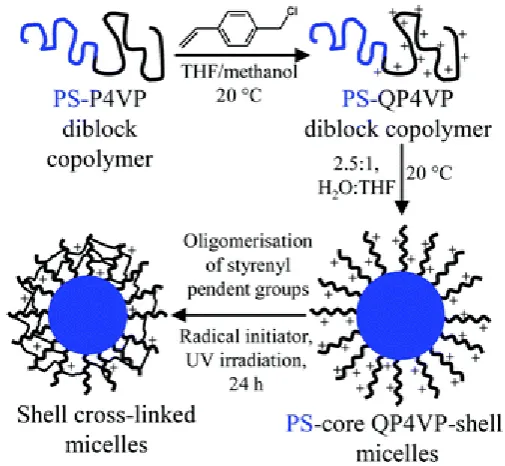
Polymersome Modification and Functionalisation via
Particle-Bilayer Interactions
by
Rong Chen
A thesis submitted in partial fulfilment of the requirements for the degree
of Doctor of Philosophy in Chemistry
Rong Chen ... 1
University of Warwick, Department of Chemistry ... 1
Chapter 1 A review of vesicle functionalisation: Amphiphiles self-assembly, production techniques, bilayer modification and reinforcement ... 1
1.1 Self-assembly of amphiphiles in solution ... 1
1.2 Lipids vesicles ... 3
1.3 Polymer vesicles and self-assembly of block copolymers ... 4
1.3.1 Polymeric micelles ... 4
1.3.2 Block copolymer cylindrical micelles (rods) ... 5
1.3.3 Block copolymer vesicles ... 6
1.4 Vesicle production techniques ... 7
1.4.1 Bangham Method ... 7
1.4.2 Templated film hydration ... 8
1.4.3 Electroformation ... 9
1.4.4 Homogenisation/extrusion ... 10
1.4.5 Sonication ... 11
1.4.6 Freeze-pump-thaw ... 11
1.4.7 Inkjet printing ... 11
1.4.8 Nanoparticle induce self-assembly ... 13
1.4.9 Solvent addition ... 13
1.4.10. Use of double emulsions and microfluidics. ... 15
1.5 Reinforcement of block copolymer self-assembly aggregates ... 16
1.5.1 Shell crosslinked micelles ... 16
1.5.2 Interaction of nanoparticles with polymersomes. ... 17
1.6 Application for drug delivery ... 19
1.7 Aims and scope of investigation ... 20
Chapter 2 Polymer Vesicles with a Colloidal Armour of Nanoparticles ... 27
2.1 Introduction ... 27
2.2 Experimental ... 30
2.2.1 Synthesis of N-(n-propyl)-2-pyridyl methanimine (Propyl ligand) ... 30
2.2.3 Synthesis of Poly(n-butyl methacrylate) -block-poly(2-(dimethylamino) ethyl methacrylate) (pBMA-block-pDMAEMA) (PBMA-PDMAEMA) by atom transfer radical polymerisation (ATRP)... 31
2.2.4 Synthesis of polymer latex particles by soap-free emulsion polymerisation ... 32
2.2.5 Preparation of polymersomes by the method of reverse solvent addition ... 34
2.2.6 NS-TEM preparation with trehalose presence ... 34
2.2.7 Preparation of particle armoured vesicles ... 35
2.2.8 Cryo-TEM sample preparation ... 35
2.2.9 Cryo-SEM sample preparation... 35
2.3 Results and discussion ... 37
2.3.2 Unmodified Polymersome formation and EM analysis ... 38
2.3.3 Polymersomes armoured with polystyrene latex particles ... 42
2.3.4 Polymersomes armoured with inorganic particles ... 47
2.3.5 Polymersomes armoured with film forming nanoparticles. ... 50
2.3.6 Polymersomes armoured with gel formation latex spheres. ... 53
2.3.7 Asymmetric assembly of nano particles on polymersomes ... 56
2.4 Conclusions ... 62
Chapter 3 Triggered Release of Polymersome by Bubble Generation via Bilayer Embedded Particles ... 66
3.1 Introduction ... 66
3.2 Experimental ... 68
3.2.1 W/O/W Double emulsion microfluidic device fabrication ... 68
3.2.2 Preparation of monodisperse polymersomes formed from Poly(n-butyl methacrylate) -block-poly(2-(dimethylamino) ethyl methacrylate) (pBMA-b-pDMAEMA) by microfluidic double-emulsion device. ... 70
3.2.3 Characterisations of the double-emulsion droplets and the polymersomes formed ... 70
3.2.4 Stimuli responsive study of particle embedded polymersomes prepared from microfluidics. ... 71
3.2.5 Ion Selective electrode measurement for polymersome release profile study. .... 72
3.3 Results and discussion ... 74
3.3.1 Polymersomes formation from double-emulsion droplets as templates, observation and characterisation. ... 74
3.3.2 Triggered release behaviour of the polymersomes by hydrogen peroxide stimulus ... 80
3.3.3 Polymersomes release behaviour when applied a low concentration of hydrogen peroxide stimulus... 83
3.3.4 Fluoride Ion Selective Electrode (ISE) measurements for polymersome releasing behaviour study. ... 85
3.4 Conclusions. ... 89
Chapter 4 Morphological transitions in polymer vesicles upon bilayer swelling with small hydrophobic molecules in water ... 93
4.1 Introduction ... 93
4.2 Experimental ... 97
4.2.1 Materials ... 97
4.2.2 Macroinitiator synthesis ... 97
4.2.3 PEG45-PMMA170 block copolymer synthesis ... 98
4.2.4 Polymersome formation ... 98
4.2.5 Polymersome dialysis... 99
4.2.6 Polymersome swelling ... 99
4.3 Results and discussion ...101
4.3.1 MMA swelling for both PMMA and PBMA based polymersomes ...101
4.32 BMA swelling of PBMA based polymersomes ...107
Chapter 1 A review of vesicle functionalisation:
Amphiphiles self-assembly, production techniques,
bilayer modification and reinforcement
1.1
Self-assembly of amphiphiles in solution
Amphiphiles are often described as molecules that possess a dual
hydrophobic-hydrophilic character. The hydrophobic tail is often one or two long
alkyl chains, while the hydrophilic part is known to be ionic and commonly referred
to as head group of the molecular structure. Amphiphiles come in a variety of forms,
both naturally occurring phospholipids, such as phosphatidyl choline, which is the
major component of biological membranes and can be obtained from a variety of
readily available source, e.g. Soybeans or egg yolk, and the fully synthetic such as
sodium dodecyl sulphate (SDS) or cetyltrimethylammonium bromide (CTAB), which
has been widely used in commercial products, such as hair conditioner and facial
cleanser. Amphiphilic molecules have gained considerable interest among scientists
for not only its use as surfactants but also the potential applications and their
microscopic morphologies in bulk and in aqueous solutions, which motivates the
studies including those on self-assembly principles, theories, structures and
functionalisation of the amphiphilic molecules. In aqueous solution amphiphiles
undergo self-assembly in order to minimise energetically unfavourable
hydrophobe/water interactions, which results in various morphologies. The factors
that determine the nanostructures of these assemblies are influenced by the packing
parameter, which is dependent on the dimensions of amphiphilic molecules.
Taking sodium dodecyl sulphate (SDS), one of the most widely used amphiphiles as
an example, when this surfactant is dispersed in water, the SDS molecules aggregate
into a globular structure, which the hydrophilic heads are in contact with the water,
while the hydrophobic tails are shielded from the water to form a hydrophobic core;
thus a so called micelles structure is formed with approximately 2-3 nm and contains
2
used instead of water, which hydrophilic heads gather in the centre of the structure
and hydrophobic tails spread into the solvent.
However, micelle structure is only one of the nanostructures that amphiphilic
molecules can assemble in solution. In order to study the self-assembly behaviour and
its principle, a dimensionless “packing parameter”, p, is defined in equation (1.1)[1]:
Where v is the volume of the hydrophobic chains, ao is the optimal area of the
hydrophilic group, and lc is the length of the hydrophobic tail. Therefore, the
self-assembled morphology of a given molecule in a particular solvent can usually be
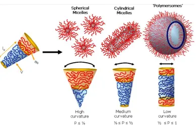
predicted by the packing parameter. Generally, spherical micelles are favoured
structure when p<1/3, whereas when the p is between 1/3 and 1/2 then the cylindrical
rods can be expected. Enclosed membrane structures also known as vesicles, are
formed when p is between 1/2 and 1. (Figure 1.1)[1, 2]
Figure 1.1 Various self-assembled structures formed by amphiphilic block
copolymers in a block-selective solvent. The type of structure formed is due to the
inherent curvature of the molecule, which can be estimated through calculation of its
[image:8.595.93.483.380.633.2]1.2 Lipids vesicles
Vesicles that are formed from mainly phospholipids molecules, also known as
liposomes, are arguably the most dominant and important structures that are present in
nature because the arrangement of molecules that a bilayer forms are the fundament
of all cell membranes. Despite the fact that the size and properties of membrane
varied due to the differences of the membrane composition and the presence of
functionalised molecules, biological membranes are generally composed of
phospholipids, glycolipids, proteins, glycoproteins and cholesterol. In the early stage
of the scientific research history, phospholipids were obtained from natural sources,
such as egg or brain tissue. However, in present, scientists have developed a range of
synthetic ways to obtain these molecules, which have the advantages of higher purity
and productivities. Today, there is still much research continuing using phospholipids
as a reliable and biocompatible system. Due to the relatively high fluidity and the
structure of phospholipids, these amphiphilic molecules have high mobility in
aqueous and self-assemble in a rapid rate, therefore bilayer aggregates and vesicles
form spontaneously in aqueous conditions once the critical concentration has been
reached. However, because of the specialised structure and the low molecular weight
(less than 1 kilodalton) of phospholipids, liposomes are sensitive to change in
concentration and pH and usually have a soft and flexible surface at ambient
temperature. When using liposomes as nanocarriers, the thin bilayer shell can easily
be broken by external forces, which results in unintended release of the inner content;
or in other cases, the encapsulated substances can gradually diffuse across the bilayer
as a result of high permeability for small molecules which caused by the low
4
Figure 1.2. Phosphatidyl choline an example of a phosphoglyceride.
1.3 Polymer vesicles and self-assembly of block copolymers
Different structures can be obtained via self-assembly of amphiphilic polymeric
molecules such as micelles, rods and vesicles, which are the result of hydrophilic and
hydrophobic domains of molecules interacting with a given solvent, e.g. water, in a
similar way as phospholipids. During the last two decades, chemists have designed
more advanced molecules with amphiphilic properties, which can respond to changes
including but not limited to solvent type, temperature, oxidant, pH, light or magnetic
field adding a further dimension to the molecules, which expand the potential
application of the assembled structures.
1.3.1 Polymeric micelles
A simple spherical micelle structure is formed when the hydrophilic part of the
polymer molecule occupies much larger space than the hydrophobic part in aqueous
media due to the fact that, with a packing parameter value less than a third, the
curvature of the outer shell of each section formed by a polymer molecule limits the
space for other molecules to occupy, which results in a core shell spherical structure
with a spherical hydrophobic core surrounded by hydrophilic coronal chains.[3, 4]
The size of spherical micelles is relatively smaller than other type of self-assembled
aggregates due to the fact that the radius of the core cannot exceed the chain length in
their planar zigzag configuration. [5] The spherical micelles can be considered as the
starting morphology for other aggregates when preparing cylinder or vesicle solutions
micelles, while the hydrophobic cores provide a possible location for encapsulation of
hydrophobic drugs [6-8] or fluorescence probes [8], and a range of other substances
such as DNA or enzymes.[5, 7, 8] Therefore, spherical micelles have been studied
extensively for application in drug delivery system and biological imaging.[5, 7]
Moreover, complex micelles such as schizophrenic diblock copolymer micelles,[9]
Janus micelles with two chemically distinct hemispheres,[10-12] and
multicompartmental‘hamburger’ micelles[13] have been developed and reported.
Figure 1.3 Schematic and Transmission electron micrographs of ‘hamburger’ micelles
1.3.2 Block copolymer cylindrical micelles (rods)
Worm-like micelles, formed from block copolymers, have been widely reported.
Infinitely long cylinders are energetically favourable relative to shortened cylinders
with incorporated end-defects. The packing parameter of this self-assembled structure
has a very narrow window, which means that the polydispersity of the block
copolymer that made for this structure plays an important role in the formation of
defects such as end caps (more energetically favourable) and branch points (less
favourable).[14] Literature reports of giant[15] and short worms,[16, 17] y-junction
and end cap defects[18, 19], and even worm-like micellar networks demonstrate the
increasing complexity associated with amphiphilic block copolymer
self-assemblies.[2] Discher et. al. reported giant and flexible worm micelles
self-assembled from degradable copolymer poly(ethylene
oxide)-block-polycaprolactone. Such worm micelles spontaneously shorten to
generate spherical micelles, triggered by polycaprolactone hydrolysis,[20] which
6
reported that the secondary self-assembly of ABC triblock copolymer spherical
micelles can, in specific conditions form giant segmented worm-like micelles.[21]
Moreover, there have been reports of the selective formation of segmented,[22]
toroidal,[23] and helical[24] cylindrical micelles from the triblock copolymers.
1.3.3 Block copolymer vesicles
Block copolymers that mimic lipid amphiphilicity can self-assemble into vesicles in
dilute solution, which have been given the name “polymersomes”. The investigation
and formation of vesicles and other aggregates from block copolymers was initially
led by the groups of Eisenberg[4, 25], Hammer and Disher.[26] Unlike phospholipids
or other classical synthetic amphiphiles, polymer molecules are considerably much
larger ranging from thousands to millions of grams per mol, which can be orders of
magnitude greater than those of lipids. The physical characterisation of block
copolymer vesicles has shown that these structures are more robust than their
naturally occurring counterparts, which is attributed to its significant higher molecular
weight. Membrane “toughness” or cohesive energy density for polymersomes taken
as the integral of the tension with respect to the areal strain as given by the formula:
It has been reported with a value of 2.2 mJ/m2 compared with phospholipids at 0.05 – 0.5 mJ/m2. Moreover, the membrane permeability can be affected by the thickness of the bilayer as well as the porosity. It has been shown that the permeability of
polymeric membranes is at least 10 times less than phospholipids as a result of
significant increase in thickness.
The first synthesised vesicle forming amphiphiles used asymmetric A-B block
copolymers [26, 27], however, it has also been reported using A-B-A[28-31],
A-B-C[32, 33] and A-B-C-A.[34] Block copolymers composed of polylactide,
polyethyleneoxide and polycaprolactones have also become a popular choice due to
1.4 Vesicle production techniques
A significant number of techniques have been developed for vesicle preparation from
both lipid and amphiphilic polymer molecules. It is worth noting that, not all
amphiphiles spontaneously form vesicles when dispersed in aqueous media.
Furthermore, even if vesicles form spontaneously upon dispersion, it usually gives a
polydisperse system of uni and multilamellar vesicles. Further processing protocols
are applied for vesicle dispersions to improve the homogeneity of solutions. Scientist
have developed different techniques for different types of amphiphilic molecules to
prepare vesicle solution and in some cases, as the hydrophobic part of the amphiphiles
is rigid at desired temperature without organic solvent presence, more than one
solvents are used to provide extra fluidity therefore stability to the bilayer.
1.4.1 Bangham Method
This classical procedure was used firstly by Alec Bangham in his research work with
vesicles and is well known as film hydration method and is most commonly employed
with liposomes preparation.[37] It yields a broad size distribution of vesicles, which
can be used directly or subjected to homogenisation processing, such as extrusion or
sonication. It has also been demonstrated with polymeric surfactants, which has a
relatively low glass transition temperature.[38]
Typically, the amphiphiles are dissolved in chloroform/methanol and then cast onto
the surface of a curved glass, for example a glass jar, by evaporation of organic
solvent under nitrogen flow or vacuum. Aqueous buffer, water or a sucrose solution is
added after the sample is dried. Gentle shaking or vibration is applied to yield vesicles,
which form spontaneously. In some cases, mild heat can be also applied to increase
the fluidity of the chemicals. The action of the solvent and osmotic forces then lift
amphiphiles formed film from the glass surface, which then driven by spontaneous
curvature of the molecules and the packing parameter to form vesicles. This technique
8
film thickness as a result of their high molecular weight and high glass transition
temperature.
1.4.2 Templated film hydration
This technique was developed based on classical film hydration and gives much better
control in both size distribution and structure complexity. Ryan and co-workers have
firstly reported this method for giant unilamellar vesicles formation (GUV). In their
work, a plasma-cleaned gold coated silicon wafers were treated with photolithography
under a TEM grid mask in order to fabricate a micron sized square feature patterned
substrate. Then a PEO-PBO copolymer with a molecular weight of 2.3k, which
prepared by anionic polymerisation, was spin-cast to generate films several hundred
nanometres thick, followed by spontanueous dewetting process, which result in a
collection of vesicles with sizes corresponding to the original TEM grid used.[39]
Figure1.4 Schematic representation of the controlled formation of vesicles:
(i) Resulting drop profile following dewetting. (ii) Hydration resulting in microphase
separation—hexagonal rod phase (blue: hydrophilic, red: hydrophobic). (iii) Further
hydration at the surface resulting in surface lamellae and further internal phase
separation. (iv) Expansion of exterior bilayer. (v) Detachment. (vi) Surface
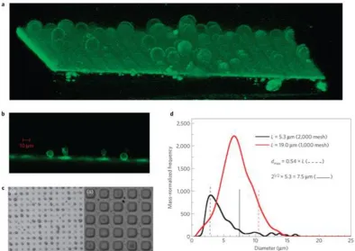
Figure 1.5. Images of the polymer islands, the vesicle formation process and vesicle
size distributions. Image taken from ref [39]
1.4.3 Electroformation
One approach that has been proved to be successful in the production of giant vesicles
with both phospholipids and block copolymers is the use of an AC current in the
electroformation method. Firstly, two glass slides coated with a layer of
semi-conductor, commonly indium tin oxide, also widely used in LCD panel, attached
to a power supply[40]. One of the slides has an enclosed well, capable of taking small
volumes of conducting liquid, usually salt aqueous solution or glucose/dextran. The
same protocol is used as film hydration method to cast a thin lipid or polymer film on
this slide. The well is then filled with a conducting liquid and then covered with the
second slide, with the semi-conductor in contact with the water. The two slides are
kept pressed together to prevent liquid from escaping and to ensure a good contact
with the water to make a circuit. A typical 1-10 V at a frequency of 10 Hz is applied.
10
1-2 hours.
A modified version of this method involves the use of a PDMA stamp to pattern the
ITO glass surface. Giant phospholipid vesicles were formed only from the squares
which had direct contact with the glass at the time of printing.[41]
Instead of using ITO glass, there is a second version of electroformation method
which involves two Pt [42, 43] or Au[31] wires spaced 2-3 mm apart, lipid film is
casted on the electrodes and a well of liquid is also required to complete the circuit.
Reported vesicles dimensions range from 0.1-300 μm[44]. Early reports of successful
vesicle production by this method used charged phospholipids,[45] however, more
and more recent work showed successful production of polymersomes, from nonionic
block copolymers with low glass transition temperatures.
Both versions of the electroformation technique have shown that the electric field
helps to gently shake the deposited lipids from surface of either the ITO glass or metal
electrode. It is the osmotic pressures and electrostatic forces that drive phospholipids
to form liposomes. Therefore, an upper concentration limit usually exist for solutes,
since the increasing of solute concentration also increases osmotic pressure and
represses the lipids film.
1.4.4 Homogenisation/extrusion
One of the best approaches to yield relatively narrow size distribution vesicles is to
extrude the vesicles in a homogeniser. Commercial devices are available on the
market, which all devices will subject the fluid to high shear, collision and cavitation
by forcing it through tiny holes at high pressure, then a more homogenised dispersion
is obtained. The high pressure that applied in the process disrupts the bilayer in large
lamellae or spontaneously formed multilamellar vesicles. This leads to a
reorganisation of the molecules into smaller unilamellar vesicles. After disruption of
the bilayer in the homogeniser, the solution is then immediately passed through
membranes with chosen porosity of desired size. Large objects will be separated from
monodisperse, depending on the number of extrusion, pore size of the membrane and
the applied pressure. [46, 47]
1.4.5 Sonication
This technique makes use of high energy in the form of ultrasonic waves, which play
a role in disrupting the lamellar bilayers in large lamellae or multilamellar vesicles. It
has been reported that this approach leads to the production of very small vesicles
with variable population distributions. [48, 49]
There are a number of factors affecting the efficiency of this approach, including the
processing time, power and type of ultrasound apparatus. However, this method
cannot be applied to “hard” materials, which normally have a high glass transition
temperature and large molecular weight. This is due to the fact that amphiphiles with
rigid chains can hardly move and rearrange in the water without the aid of organic
solvent, which results in a trapped thermodynamic state, therefore fail to
self-assemble into vesicles.
1.4.6 Freeze-pump-thaw
This technique does not directly lead to the formation of vesicles; therefore it is
commonly used with homognisation or sonication. By forming ice crystals, the
bilayers that formed in the solution are disrupted into small pieces. The result is
increased hydration of lipids upon thawing. The following reformulation to
unilamellar vesicles can be achieved more easily by other homogenisation method.
1.4.7 Inkjet printing
This method has been first reported by Förster and coworkers in order to demonstrate
12
cartridge is filled with a solution (0.1- 5 wt%) of the vesicle-forming amphiphiles in
ethanol or other water miscible solvents such as THF or dioxane. Routinely, an
experiment consists of printing three black pages with the highest print quality, which
corresponds to the highest ink throughput[50]. Approximately 1-1.5 mL of the
solution, depending on the cartridge type, is then “printed” into 10 ml of water under
stirring. Monodisperse unilamellar vesicles in the diameter size range of 50-200 nm
can be directly and reproducibly prepared. Modern inkjet printers produce droplets
with volumes in the picoliter range with high reproducibility,[51, 52] which allows
vesicle formation to be controlled with good precision.
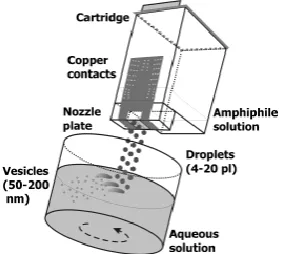
Figure 1.6 Scheme of the preparation of nanometer-sized vesicles using simple inkjet
printing technology. A solution of a vesicle-forming amphiphile is filled into a
cartridge and “printed” into a stirred aqueous solution, where the amphiphiles
spontaneously assemble into vesicles. The printers are modified to hold the printhead
[image:18.595.227.368.289.416.2]in a fixed position. [50]
Figure 1.7 Cryo-TEM images of a) egg-PC vesicles prepared with a HP 695C printer
and b) P2 VP29-PEG15 vesicles prepared with a HP 890 printer. All vesicles are small
and unilamellar with, in the case of the polymersomes, very narrow size
1.4.8 Nanoparticle induce self-assembly
Park and co-workers have reported on how to control the self-assembly of magnetic
nanoparticles and a prototypical amphiphilic block-copolymer into polymersomes,
micelles and core-shell type micelles by controlling the solvent-nanoparticle and
polymer nanoparticles interactions. Incorporation of nanoparticles drastically affects
the self-assembly structure of block-copolymers by modifying the relative volume
ratio between the hydrophobic block and the hydrophilic block.[53] As a consequence,
the self-assembly of micelle-forming block-copolymers typically produces
magneto-polymersomes instead of magneto-micelles. In this case, the packing
parameter of the block copolymers is in the range of micelle formation. However, by
adding oleic acid bond magnetic nanoparticles, the hydrophobic block can be
considered extended, which results in the change of the effective volume ratio
between two blocks.
Figure 1.8. Self-assembly of nanoparticles and block copolymers. (a) Magneto-core
shell assemblies formed when DMF/THF mixture (96.8% DMF) was used as the
initial solvent for polymers and nanoparticles. (b) Magneto-micelles assembled in
THF. (c) Magneto-polymersomes assembled in dioxane/THF (96.8% dioxane).[53]
1.4.9 Solvent addition
This technique was originally proposed for use with phospholipid vesicles, but now is
commonly used with block copolymer amphiphiles, which are too hydrophobic to be
14
The idea of the solvent addition method is to firstly dissolve amphiphiles in a good
solvent for both blocks. Then a second solvent is chosen, which is good solvent for
one block but not the other and is also miscible with the first solvent. The result is that
as the concentration of the second solvent increases, the amphiphiles arrange
themselves into a range of three diamensional equilibrium structures to minimise the
unfavourable hydrophobe-water interactions. Typically, block copolymers are
dissolved in an organic solvent such as THF and then water is slowly added to the
system with vigorous stirring. Dialysis is usually applied additionally, which can take
days to weeks for the organic solvent to be removed completely. The addition of the
second solvent is often required to be slow enough, so that the polymer chains in the
solution can have enough time for relaxation and rearrangement. One of the
advantages of this approach is that simply by stopping addition of the solvent, the
structures formed for that solvent composition are frozen; the sample can be taken out
[image:20.595.110.487.405.613.2]for further study.
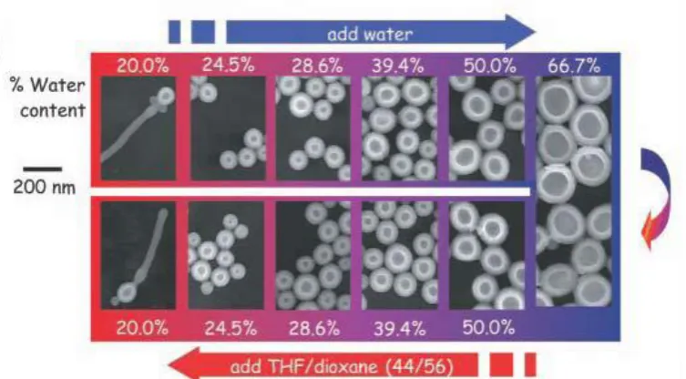
Figure 1.9 A diagram showing changing morphology and size with changing solvent
environment, note the increase in vesicles size as water moves toward 66%.[55]
Besides typical structures such as micelles, rods and vesicles are formed, a range of
1.4.10. Use of double emulsions and microfluidics.
This technique uses microfluidic devices to form water-in-oil-in-water
double-emulsion droplets in aqueous.[56] Typically, an amphiphilic block copolymer
is dissolved in the oil (organic phase), which is immiscible with water and capillary
based device is used to generate droplet in the droplet structure. After the formation of
the emulsion, the organic solvent is evaporated and the block copolymer chains
adsorbs to the interfaces between the oil and water phases upon evaporation of the
middle phase, then polymersome forms.
The Weitz group has developed a range of different types of microfluidic devices by
using glass capillaries. These devices enable not only the possibility of which the
monodisperse polymersomes can be made, but also the possibility to generate other
core-shell or multicompartment structures.[57-59]
Figure 1.10. Schematic of the microcapillary geometry for generating double
emulsions. The geometry requires the outer phase to be immiscible with the middle
phase, which is in turn immiscible with the inner phase. However, the inner phase can
be miscible with the outer phase.[60]
Polymersomes formed by this method have been used for a range of copolymers
including PBA-PAA, PBMA-PDMAEMA, PS-PEO, PBD-PEO etc., indicating that
the technique is a generally applicable on for polymers of varying glass transition
temperatures. Reported diameters are in the range of 10-300 μm with bilyer
(sometimes multiple bilayer) thicknesses of few micrometer, which can be controlled
by the polymer concentration in the organic phase. In addition to thicker than average
bilayers, the polymersomes can sometimes have one side or spot thicker than the rest
16
compatible organic solvent is used as co-solvent.[61]
1.5 Reinforcement of block copolymer self-assembly aggregates
Efforts have been made to develop different ways of giving different functionalities to
polymer molecules. For this reason, those aggregates that assembled from block
copolymers can possess various physical and chemical properties, which arises from
every single molecule in the structures. One of the directions is to increase the
stability and mechanical properties of micelles, cylinders or vesicles to enable them
suitable for special applications.
1.5.1 Shell crosslinked micelles
One of the fundamental problems with block copolymer micelles is that when the
polymer concentration drops below its critical micelles concentration (CMC),
spontaneous dissociation can happen. However, in 1996, Wooley’s group [62]
reported that cross-linking micelles coronas at high dilution led to the structure of
[image:22.595.171.424.491.724.2]robust nanoparticles know as Shell Cross-Linked micelles (SCL) (Figure 1.11)
Figure 1.11 Schematic illustration of the first example of shell cross-linked micelles
Unlike conventional micelles, these new covalently-stabilised SCL micelles were
stable with respect to infinite dilution. Similar result can be achieved when
cross-linking the micelles cores.[15, 63, 64] Moreover, it has been report not only for
spherical micelles but also for cylindrical micelles, the combination of the two gives a
new complex structure with extra stability. Amphiphilic block copolymers were
micellised and shell-crosslinked in water to give cationic, spherical or anionic,
cylindrical micelles.[65, 66] The differences in surface charge and particle shape
result from the different polymers used to create these assemblies. The shell
crosslinked cylinder were assembled from polyamidoethylamine128-b-polystyrene40,
while the nanocylinders were assembled from poly(acrylic acid)96-b-polystyrene49.
Upon mixing, the cationic spheres assembled on the nanoscopic curved surfaces of
the nanocylinders and form a close-packed dense layer.[67]
Figure 1.12 Formation of shell-crosslinked nanoparticles of spherical and cylindrical
shapes, and the templated self-assembly of the spheres on the surface of a
cylinder.[67]
1.5.2 Interaction of nanoparticles with polymersomes.
Polymersomes as synthetic analogues to liposomes have gain great interests due to
their increased thickness, rigidity and stability. [55, 68] The interaction of
18
nanoparticles into a favourably interaction polymer domain or at the interface
between two polymers [69, 70]. Morphological changes of block copolymer
assemblies can be induced by the incorporation of nanoparticles, which play an active
role in the self-assembly of the block copolymer into membranes [53, 71]. Eisenberg
and Mai[72] showed that nanoparticles can selectively be incorporated into the central
part of block copolymer vesicle bilayer walls by simply coating the particles with
similar structure diblock copolymers, which enabled the particles to be localised in
the central part of the bilayer.
Duan and coworkers have reported a new class of plasmonic vesicular nanostructures
assembled from amphiphilic gold nanocrystals with mixed polymer brush coatings.
Instead of decorating polymersomes, gold nanoparticles have been incorporated with
both hydrophilic and hydrophobic brushes to obtain amphiphilicity,[73] which can
therefore self-assemble into vesicular nanostructures with designed stimuli responsive
property. (Figure 1.13)
Figure 1.13 Schematic illustration of self-assembly of amphiphilic nanocrystals with
1.6 Application for drug delivery
In addition to providing a facile model system of the more complex cell membrane,
vesicles, along with micelles[74] and dendrimers[75, 76] have been applied in
encapsulation technology for drug delivery[77] and cosmetics, delivering vitamins
and oils. The potential applications for polymers to aid in the delivery of drugs has
gained more and more interest and polymers have been developed that have the
ability to disrupt and penetrate the bilayer membrane[78, 79]. It has also been
demonstrated that nano-aggregates, such as shell cross-linked micelles can deliver
target molecules to a site and release the contents under the correct conditions[80-83]
and that the delivery rates may be modified with small modifications to the makeup of
the aggregate forming species[84]. Indeed, phospholipids have been formulated into
“transferosomes”, vesicles made from a mixture of phospholipids, with a highly
flexible hydrophilic membrane such that they can aid in the transdermal transfer of an
encapsulated drug[85].
It is possible to attach biologically actives or interesting molecules such as biotin to a
polymer chain, which has a very strong specific interaction with avidin. [86, 87]These
modified polymer chains can then be included into a vesicle or micelle with a view to
a biological or bio-recognition application[88]. One obvious criterion for biomedical
applications is that the delivery vehicle itself does no harm to the target organism in
which it is used and to this end much recent research has focused on the synthesis of
20
1.7 Aims and scope of investigation
This thesis investigates the reinforcement of polymersomes with particles and their
structural morphologies. The thesis is outlined as follow:
In Chapter 2, vesicles are formed from PBMA-PDMAEMA block copolymers. In an
attempt to reinforce the vesicle bilayer by the assembly of colloidal nanoparticles, the
polymersomes are treated with variety of particles and analysed by microscopy
technique.
In Chapter 3, stimuli responsive polymersomes are fabricated via microfluidic
approach and the embedded micron sized particles are the key to this bubble
generating property. Both instant and slow release behaviours are studied via
microscopic technique and ion selective electrode measurement.
In Chapter 4, the morphological transitions of the polymersomes when exposed to
small hydrophobic molecules are studied. The influence of the small organic
1. Vriezema, D.M., et al., Self-Assembled Nanoreactors. Chemical Reviews, 2005. 105(4): p. 1445-1490.
2. Blanazs, A., S.P. Armes, and A.J. Ryan, Self-Assembled Block Copolymer Aggregates: From Micelles to Vesicles and their Biological Applications.
Macromol Rapid Commun, 2009. 30(4-5): p. 267-77.
3. Cameron, N.S., M.K. Corbierre, and A. Eisenberg, 1998 E.W.R. Steacie Award Lecture Asymmetric amphiphilic block copolymers in solution: a morphological wonderland. Canadian Journal of Chemistry, 1999. 77(8): p. 1311-1326.
4. Zhang, L. and A. Eisenberg, Multiple Morphologies of "Crew-Cut" Aggregates of Polystyrene-b-poly(acrylic acid) Block Copolymers. Science, 1995. 268(5218): p. 1728-1731.
5. Mai, Y. and A. Eisenberg, Self-assembly of block copolymers. Chemical Society Reviews, 2012. 41(18): p. 5969-5985.
6. Riess, G., Micellization of block copolymers. Progress in Polymer Science, 2003. 28(7): p. 1107-1170.
7. Kabanov, A.V., E.V. Batrakova, and V.Y. Alakhov, Pluronic block copolymers as novel polymer therapeutics for drug and gene delivery. J Control Release, 2002. 82(2-3): p. 189-212.
8. Maysinger, D., et al., Fate of micelles and quantum dots in cells. Eur J Pharm Biopharm, 2007. 65(3): p. 270-81.
9. Bütün, V., et al., A brief review of ‘schizophrenic’ block copolymers. Reactive and Functional Polymers, 2006. 66(1): p. 157-165.
10. Erhardt, R., et al., Janus Micelles†. Macromolecules, 2001. 34(4): p. 1069-1075.
11. Erhardt, R., et al., Amphiphilic Janus Micelles with Polystyrene and Poly(methacrylic acid) Hemispheres. Journal of the American Chemical Society, 2003. 125(11): p. 3260-3267.
12. Voets, I.K., et al., Double-Faced Micelles from Water-Soluble Polymers.
Angewandte Chemie International Edition, 2006. 45(40): p. 6673-6676.
13. Li, Z., M.A. Hillmyer, and T.P. Lodge, Control of Structure in Multicompartment Micelles by Blending μ-ABC Star Terpolymers with AB Diblock Copolymers. Macromolecules, 2005. 39(2): p. 765-771.
14. Dan, N. and S.A. Safran, Junctions and end-caps in self-assembled non-ionic cylindrical micelles. Advances in Colloid and Interface Science, 2006. 123–126(0): p. 323-331.
15. Won, Y.-Y., H.T. Davis, and F.S. Bates, Giant Wormlike Rubber Micelles.
Science, 1999. 283(5404): p. 960-963.
16. Won, Y.-Y., et al., Cryogenic Transmission Electron Microscopy (Cryo-TEM) of Micelles and Vesicles Formed in Water by Poly(ethylene oxide)-Based Block Copolymers. The Journal of Physical Chemistry B, 2002. 106(13): p. 3354-3364.
22
2006. 39(3): p. 1199-1208.
18. Jain, S. and F.S. Bates, On the Origins of Morphological Complexity in Block Copolymer Surfactants. Science, 2003. 300(5618): p. 460-464.
19. Jain, S., et al., Disordered Network State in Hydrated Block-Copolymer Surfactants. Physical Review Letters, 2006. 96(13): p. 138304.
20. Geng, Y. and D.E. Discher, Hydrolytic Degradation of Poly(ethylene oxide)-block-Polycaprolactone Worm Micelles. Journal of the American Chemical Society, 2005. 127(37): p. 12780-12781.
21. Zhu, J. and W. Jiang, Self-Assembly of ABC Triblock Copolymer into Giant Segmented Wormlike Micelles in Dilute Solution. Macromolecules, 2005. 38(22): p. 9315-9323.
22. Cui, H., et al., Block Copolymer Assembly via Kinetic Control. Science, 2007. 317(5838): p. 647-650.
23. Pochan, D.J., et al., Toroidal Triblock Copolymer Assemblies. Science, 2004. 306(5693): p. 94-97.
24. Zhong, S., et al., Helix self-assembly through the coiling of cylindrical micelles. Soft Matter, 2008. 4(1): p. 90-93.
25. Zhang, L., K. Yu, and A. Eisenberg, Ion-Induced Morphological Changes in “Crew-Cut” Aggregates of Amphiphilic Block Copolymers. Science, 1996. 272(5269): p. 1777-1779.
26. Discher, B.M., et al., Polymersomes: Tough Vesicles Made from Diblock Copolymers. Science, 1999. 284(5417): p. 1143-1146.
27. Zhang, L. and A. Eisenberg, Multiple Morphologies and Characteristics of “Crew-Cut” Micelle-like Aggregates of Polystyrene-b-poly(acrylic acid) Diblock Copolymers in Aqueous Solutions. Journal of the American Chemical Society, 1996. 118(13): p. 3168-3181.
28. Napoli, A., et al., Oxidation-responsive polymeric vesicles. Nat Mater, 2004. 3(3): p. 183-9.
29. Nardin, C., et al., Polymerized ABA Triblock Copolymer Vesicles. Langmuir, 1999. 16(3): p. 1035-1041.
30. Schillén, K., K. Bryskhe, and Y.S. Mel'nikova, Vesicles Formed from a Poly(ethylene oxide)−Poly(propylene oxide)−Poly(ethylene oxide) Triblock Copolymer in Dilute Aqueous Solution. Macromolecules, 1999. 32(20): p. 6885-6888.
31. Sauer, M., et al., Ion-carrier controlled precipitation of calcium phosphate in giant ABA triblock copolymer vesicles. Chemical Communications, 2001(23): p. 2452-2453.
32. LoPresti, C., et al., Polymersomes: nature inspired nanometer sized compartments. Journal of Materials Chemistry, 2009. 19(22): p. 3576-3590. 33. Liu, F. and A. Eisenberg, Preparation and pH Triggered Inversion of Vesicles
from Poly(acrylic Acid)-block-Polystyrene-block-Poly(4-vinyl Pyridine).
Journal of the American Chemical Society, 2003. 125(49): p. 15059-15064. 34. Brannan, A.K. and F.S. Bates, ABCA Tetrablock Copolymer Vesicles.
35. Meng, F., et al., Biodegradable Polymersomes. Macromolecules, 2003. 36(9): p. 3004-3006.
36. Ghoroghchian, P.P., et al., Bioresorbable Vesicles Formed through
Spontaneous Self-Assembly of Amphiphilic Poly(ethylene
oxide)-block-polycaprolactone. Macromolecules, 2006. 39(5): p. 1673-1675. 37. Bangham, A.D. and R.W. Horne, Negative staining of phospholipids and their
structural modification by surface-active agents as observed in the electron microscope. Journal of Molecular Biology, 1964. 8(5): p. 660-IN10.
38. Kickelbick, G., et al., Spontaneous Vesicle Formation of Short-Chain Amphiphilic Polysiloxane-b-Poly(ethylene oxide) Block Copolymers.
Langmuir, 2003. 19(8): p. 3198-3201.
39. Howse, J.R., et al., Templated formation of giant polymer vesicles with controlled size distributions. Nat Mater, 2009. 8(6): p. 507-511.
40. Angelova, M.I., et al., Preparation of giant vesicles by external AC electric fields. Kinetics and applications, in Trends in Colloid and Interface Science VI, C. Helm, M. Lösche, and H. Möhwald, Editors. 1992, Steinkopff. p. 127-131. 41. Taylor, P., et al., A novel technique for preparation of monodisperse giant
liposomes. Chemical Communications, 2003(14): p. 1732-1733.
42. Bagatolli, L.A. and E. Gratton, Two-photon fluorescence microscopy observation of shape changes at the phase transition in phospholipid giant unilamellar vesicles. Biophys J, 1999. 77(4): p. 2090-101.
43. Bucher, P., et al., Giant Vesicles as Biochemical Compartments: The Use of
Microinjection Techniques. Langmuir, 1998. 14(10): p. 2712-2721.
44. Mueller, P., T.F. Chien, and B. Rudy, Formation and properties of cell-size lipid bilayer vesicles. Biophys J, 1983. 44(3): p. 375-81.
45. Menger, F.M. and M.I. Angelova, Giant Vesicles: Imitating the Cytological
Processes of Cell Membranes. Accounts of Chemical Research, 1998. 31(12): p. 789-797.
46. MacDonald, R.C., et al., Small-volume extrusion apparatus for preparation of large, unilamellar vesicles. Biochim Biophys Acta, 1991. 1061(2): p. 297-303. 47. Subbarao, N.K., et al., Characteristics of spectrin-induced leakage of extruded, phosphatidylserine vesicles. Biochimica et Biophysica Acta (BBA) - Biomembranes, 1991. 1063(1): p. 147-154.
48. Hunt, C.A. and G.E. McCasland, Liposome technology, vol. 1: Preparation of liposomes; vol. 2: Incorporation of drugs, proteins, and genetic materials; vol. 3: Targeted drug delivery and biological interaction. Edited by Gregory Gregoriadis. CRC Press, Inc., 2000 Corporate Boulevard N.W., Boca Raton, FL 33431. 1984. Vol. 1: 268 pp. 18 × 26 cm. $83.00. Vol. 2: 231 pp. 18 × 26 cm. $83.00. Vol. 3: 292 pp. 18 × 26 cm. $83.00. Journal of Pharmaceutical Sciences, 1985. 74(7): p. 802-802.
49. Bailey, W.J. and L.L. Zhou, Synthesis of polymerized vesicles with hydrolyzable linkages. Macromolecules, 1992. 25(1): p. 3-11.
24
51. de Gans, B.J., P.C. Duineveld, and U.S. Schubert, Inkjet Printing of Polymers: State of the Art and Future Developments. Advanced Materials, 2004. 16(3): p. 203-213.
52. Stachowiak, J.C., et al., Inkjet formation of unilamellar lipid vesicles for cell-like encapsulation. Lab on a Chip, 2009. 9(14): p. 2003-2009.
53. Hickey, R.J., et al., Controlling the Self-Assembly Structure of Magnetic Nanoparticles and Amphiphilic Block-Copolymers: From Micelles to Vesicles.
Journal of the American Chemical Society, 2011. 133(5): p. 1517-1525.
54. Moscho, A., et al., Rapid preparation of giant unilamellar vesicles. Proc Natl Acad Sci U S A, 1996. 93(21): p. 11443-7.
55. Discher, D.E. and A. Eisenberg, Polymer Vesicles. Science, 2002. 297(5583): p. 967-973.
56. Okushima, S., et al., Controlled production of monodisperse double emulsions by two-step droplet breakup in microfluidic devices. Langmuir, 2004. 20(23): p. 9905-8.
57. Kim, S.-H., et al., Multiple Polymersomes for Programmed Release of Multiple Components. Journal of the American Chemical Society, 2011. 133(38): p. 15165-15171.
58. Zhao, Y., et al., Microfluidic Generation of Multifunctional Quantum Dot Barcode Particles. Journal of the American Chemical Society, 2011. 133(23): p. 8790-8793.
59. Abbaspourrad, A., et al., Polymer Microcapsules with Programmable Active Release. Journal of the American Chemical Society, 2013. 135(20): p. 7744-7750.
60. Shum, H.C., J.-W. Kim, and D.A. Weitz, Microfluidic Fabrication of Monodisperse Biocompatible and Biodegradable Polymersomes with Controlled Permeability. Journal of the American Chemical Society, 2008. 130(29): p. 9543-9549.
61. Shum, H.C., et al., Dewetting-Induced Membrane Formation by Adhesion of Amphiphile-Laden Interfaces. Journal of the American Chemical Society, 2011. 133(12): p. 4420-4426.
62. Thurmond, K.B., T. Kowalewski, and K.L. Wooley, Water-Soluble Knedel-like Structures: The Preparation of Shell-Cross-Linked Small Particles. Journal of the American Chemical Society, 1996. 118(30): p. 7239-7240.
63. Guo, A., G. Liu, and J. Tao, Star Polymers and Nanospheres from Cross-Linkable Diblock Copolymers. Macromolecules, 1996. 29(7): p. 2487-2493.
64. Tao, J., et al., Star and Cylindrical Micelles of Polystyrene-block-poly(2-cinnamoylethyl methacrylate) in Cyclopentane.
Macromolecules, 1997. 30(9): p. 2738-2745.
65. Zhang, K., et al., Cationic shell-crosslinked knedel-like nanoparticles for highly efficient gene and oligonucleotide transfection of mammalian cells.
Biomaterials, 2009. 30(5): p. 968-977.
Cell-Penetrating Peptides (HIV Tat PTD) on CHO Cell Uptake. Bioconjugate Chemistry, 2008. 19(9): p. 1880-1887.
67. Zhang, K., et al., Composite soft-matter nanoscale objects: Nanocylinder-templated assembly of nanospheres. Soft Matter, 2009. 5(19): p. 3585-3589.
68. Sanson, C., et al., Doxorubicin Loaded Magnetic Polymersomes: Theranostic Nanocarriers for MR Imaging and Magneto-Chemotherapy. ACS Nano, 2011. 5(2): p. 1122-1140.
69. Lin, Y., et al., Self-directed self-assembly of nanoparticle/copolymer mixtures.
Nature, 2005. 434(7029): p. 55-59.
70. Haryono, A. and W.H. Binder, Controlled arrangement of nanoparticle arrays in block-copolymer domains. Small, 2006. 2(5): p. 600-11.
71. Sanchez-Gaytan, B.L., et al., Interfacial Assembly of Nanoparticles in Discrete Block-Copolymer Aggregates. Angewandte Chemie, 2007. 119(48): p. 9395-9398.
72. Mai, Y. and A. Eisenberg, Controlled Incorporation of Particles into the Central Portion of Vesicle Walls. Journal of the American Chemical Society, 2010. 132(29): p. 10078-10084.
73. Song, J., et al., Plasmonic Vesicles of Amphiphilic Gold Nanocrystals: Self-Assembly and External-Stimuli-Triggered Destruction. Journal of the American Chemical Society, 2011. 133(28): p. 10760-10763.
74. Gaucher, G., et al., Block copolymer micelles: preparation, characterization and application in drug delivery. Journal of Controlled Release, 2005. 109(1–3): p. 169-188.
75. Pantos, A., et al., Interaction of Functional Dendrimers with Multilamellar Liposomes: Design of a Model System for Studying Drug Delivery. Langmuir, 2005. 21(16): p. 7483-7490.
76. Morgan, M.T., et al., Dendritic supramolecular assemblies for drug delivery.
Chemical Communications, 2005(34): p. 4309-4311.
77. Tanner, P., et al., Polymeric Vesicles: From Drug Carriers to Nanoreactors and Artificial Organelles. Accounts of Chemical Research, 2011. 44(10): p. 1039-1049.
78. Thomas, J.L., S.W. Barton, and D.A. Tirrell, Membrane solubilization by a hydrophobic polyelectrolyte: surface activity and membrane binding. Biophys J, 1994. 67(3): p. 1101-6.
79. Hoffman, A.S., et al., Design of “Smart” polymers that can direct
intracellular drug delivery. Polymers for Advanced Technologies, 2002. 13(10-12): p. 992-999.
80. Stewart, S. and G. Liu, Block Copolymer Nanotubes. Angewandte Chemie, 2000. 112(2): p. 348-352.
81. Kiser, P.F., G. Wilson, and D. Needham, A synthetic mimic of the secretory granule for drug delivery. Nature, 1998. 394(6692): p. 459-462.
26
83. Li, Y., et al., Synthesis of Reversible Shell Cross-Linked Micelles for Controlled Release of Bioactive Agents†. Macromolecules, 2006. 39(8): p. 2726-2728.
84. Agrawal, S.K., et al., Novel drug release profiles from micellar solutions of PLA–PEO–PLA triblock copolymers. Journal of Controlled Release, 2006. 112(1): p. 64-71.
85. Cevc, G., et al., Overcoming Semipermeable Barriers, Such as the Skin, with Ultradeformable Mixed Lipid Vesicles, Transfersomes, Liposomes, or Mixed Lipid Micelles. Langmuir, 2003. 19(26): p. 10753-10763.
86. Drechsler, U., et al., Highly Efficient Biocatalysts via Covalent Immobilization of Candida rugosa Lipase on Ethylene Glycol-Modified Gold–Silica Nanocomposites. Advanced Materials, 2004. 16(3): p. 271-274.
87. Salem, A.K., et al., Porous Polymer and Cell Composites That Self-Assemble In Situ. Advanced Materials, 2003. 15(3): p. 210-213.
88. Joralemon, M.J., et al., Synthesis, characterization, and bioavailability of mannosylated shell cross-linked nanoparticles. Biomacromolecules, 2004. 5(3): p. 903-13.
89. Photos, P.J., et al., Polymer vesicles in vivo: correlations with PEG molecular weight. J Control Release, 2003. 90(3): p. 323-34.
90. Matsuda, T., I.K. Kwon, and S. Kidoaki, Photocurable biodegradable liquid copolymers: synthesis of acrylate-end-capped trimethylene carbonate-based prepolymers, photocuring, and hydrolysis. Biomacromolecules, 2004. 5(2): p. 295-305.
91. Ahmed, F. and D.E. Discher, Self-porating polymersomes of PEG–PLA and PEG–PCL: hydrolysis-triggered controlled release vesicles. Journal of Controlled Release, 2004. 96(1): p. 37-53.
Chapter 2 Polymer Vesicles with a Colloidal Armour
of Nanoparticles
2.1 Introduction
The word “polymersome” has been coined in 1999[1] to describe a hollow
bilayer-based suprastructure that consists of amphiphilic polymer molecules in liquid
medium, while conventionally, researchers has been using “liposome” for such
structure assembled from phospholipids molecules. The availability of a plethora of
synthetic macromolecular amphiphiles through advances in living polymerisation
methods has led to a surge in the preparation of vesicles made from polymer
molecules.[1, 2] Polymer vesicles have interesting chemical and physical properties,
which outperform synthetic liposomes made from phospholipids. One of the key
features is that these polymer nanocontainers are more mechanically robust, as a
result of their increased bilayer thickness, stronger chain interaction and polymer
chain entanglement,[3] which makes these hollow structures interesting as potential
drug delivery vehicles.[4] Tailored synthesis of the macromolecular building blocks
provides added complexity and functionality to their design. Use of
biodegradable,[5] oxidative responsive,[6] or pH/sugar responsive block
copolymers[7] in the fabrication of polymer vesicles allows for triggered bilayer
disintegration inducing permeability or vesicle rupture. Examples focusing on
mechanical reinforcement include the ability to cross-link the bilayer of polymer
vesicles made from poly(ethylene oxide)-block-polybutadiene,[8, 9] or provide a
polymeric scaffold through intra-bilayer polymerisation.[10]
It is plausible to consider adding functionality and potentially enhanced mechanical
strength to polymersomes by decorating their outer surface with an armour of
colloidal matter. The inspiration was taken from Nature, how it safeguards
mechanical strength in certain classes of cells and organisms. In addition to the
mechanical strength provided by the cytoskeleton of the cell, plants, fungi, and certain
28
more interest were ones with a cell wall composed of an armour of colloidal objects,
for example, bacteria coated with S-layer proteins,[11] and coccolithophorids which
have a CaCO3-based nanopatterned colloidal armour.[12]
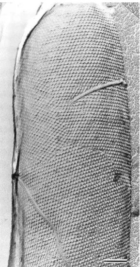
Figure 2.1 Electron micrograph of a freeze-etched preparation showing a whole cell
with a hexagonally ordered S-layer lattice. Scale bar: 100 nm.[12]
Velev demonstrated that synthetic liposomes could be coated with a layer of
ferritin.[13] Weitz and co-workers showed that crystalline rafts of microspheres could
be formed on the outside of vesicles made from mixed low-molar-mass
surfactants.[14, 15]
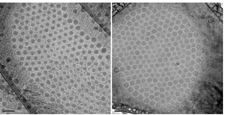
Figure 2.2 (A) Disordered and (B) more ordered rafts of particles adsorbed to the
[image:34.595.226.371.143.418.2]the rafts undergo Brownian motion, restricted by their neighbors. (C) Flaccid vesicle
covered with particles.[15]
Noteworthy is the work by Lecommandoux and co-workers who prepared polymer
vesicles which had magnetic maghemite nanoparticles incorporated into the
hydrophobic region of the bilayer.[16] Electrostatic attraction was used in this work
as drive for assembly on the outside of the bilayer. Caruso and others have shown by
using a layer-by-layer approach that electrostatic attraction can be used successfully
in the preparation of a great variety of nanoparticle hybrid capsules.[17] Wooley and
co-workers decorated cylindrical micelles with shell-cross-linked knedel-like
nanospheres.[18]
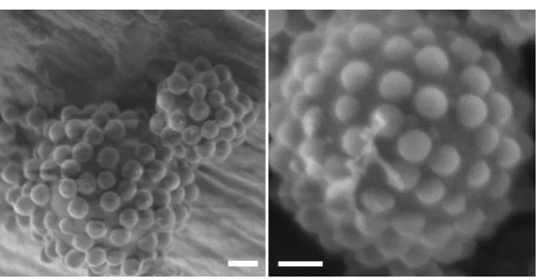
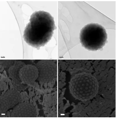
In this work it is shown not only that the polymer vesicles can be provided with a
colloidal armour made from a variety of nanoparticles, but also that postmodification
of the supracolloidal structure through film-formation and formation of a hydrogel
can be made in certain condition. Furthermore, ordering and packing patterns,
including patterns observed when polymersomes are exposed to a binary mixture of
colloids of different size and assembly behaviour when insufficient particles are
30
2.2 Experimental
2.2.1 Synthesis of N-(n-propyl)-2-pyridyl methanimine (Propyl
ligand)
2.2.1.1 Materials
n-Propylamine (98%), pyridine-2-carboxaldehyde (97%), diethyl ether (98%),
magnesium sulphate (98%) All used as delivered.
2.2.1.2 Method
Propylamine (110 mL, 1.23 mol) was added dropwise to a stirred solution of
pyridine-2-carboxaldhyde (40 mL) in diethylether (40 mL) at 0 °C. MgSO4 (12 g) was
added afterwards and the solution was stirred at ambient temperature for 10 h. The
solution was then filtered and the solvent was removed under reduced pressure. The
remaining liquid was dark orange in colour. Purification of the product was proceeded
by vacuum distillation in a rotary evaporator at 46° C under reduced pressure. The
resulting product was a bright yellow liquid. As a final step, the product was kept
under a nitrogen atomosphere at 4 °C.[19]
1
H NMR (CDCl3, δ, ppm): 8.53 (1H, m, Pyr-H), 8.30 (1H, s, Pyr-CH=N-), 7.90 (1H,
m, Pyr-H), 7.62 (1H, m, Pyr-H), 7.20 (1H, m, Phr-H), 3.62 (2H, t, J=6.4Hz,
-C=N-CH2), 1.65 (2H, m, CH2-CH2-CH3), 0.85 (3H, t, J=6.3Hz, CH2-CH3)
13C NMR (CDCl3, δ, ppm): 161.45 (Pyr-CH=N-) 154.4, 149.2, 136.3, 124.3, 121.1
2.2.3
Synthesis
of
Poly(
n-
butyl
methacrylate)
-
block
-poly(2-(dimethylamino)
ethyl
methacrylate)
(pBMA-
block
-pDMAEMA) (PBMA-PDMAEMA) by atom transfer
radical polymerisation (ATRP)
2.2.3.1 Materials
All organic solvents were of analytical grade. Ethyl α-bromoisobutyrate (98%,
Aldrich), 2-(dimethylamino) ethyl methacrylate (DMAEMA, 98%, Aldrich), CuBr
was obtained from Sigma-Aldrich and purified before use according to the method of
Keller and Wycoff (Keller, R. N.; Wycoff, H. D. Inorg. Synth. 1947, 2, 1). Prior to
use n-butyl methacrylate (BMA, 99%, Sigma-Aldrich) were passed through a short
column packed with Aluminium oxide (98%, basic, Sigma-Aldrich) in order to
remove the radical polymerisation inhibitor.
2.2.3.2 Method
In a typical ATRP procedure, a Schlenk tube was charged with solvent, purified
monomer, the initiator, and the Cu(I) catalyst. The mixture was de-aerated by three
freeze-pump-thaw cycles, placed under a nitrogen gas atmosphere, and subsequently
immersed into a preheated oil bath of 90 °C. Next the ligand, PPMI was injected into
the system by syringe to start the reaction. After the polymerisation, the tube was
rapidly cooled and exposed to air. The polymer was purified by precipitation in
methanol at -30 °C and further dried under vacuum. To synthesise pBMA, 10 g of
toluene, BMA (10 g, 70 mmol), ethyl α-bromoisobutyrate (0.185 g, 0.95 mmol), CuBr
(0.138 g, 0.96 mmol) were charged in the Schlenk tube. After the system reached
90°C, PPMI (0.3 mL, 1.94 mmol) was injected and the solution turned to dark brown.
The reaction was performed for 4 hours before quenching with cold water. Molar
mass distributions of the polymers were analysed by Gel Permeation Chromatography
(GPC) spectra were on a Varian 390-LC equipped with autosampler, refractive index
detector utilizing chloroform as mobile phase, and mixed D colums. Specific
32
weight range from 1000 to 1,000,000. Mn calc = 10000 Da. Mn (GPC-CHCl3) =
11600 Da. PDI (GPC-CHCl3) = 1.14. Mn (GPC-THF) = 12000 Da. PDI (GPC-THF)
=1.13. To synthesise the block copolymer, the same protocol was applied except
using the pBMA product as macroinitiator and DMAEMA as monomer. Mn calc =
15000 Da. Mn (GPC-CHCl3) = 14700Da. PDI (GPC-CHCl3) = 1.10. Mn (GPC-THF)
= 15300Da. PDI (GPC-THF) = 1.10
The actual molecular weight was calculated by comparing the two peaks at 4.05ppm
and 3.91 ppm in the 1H NMR spectrum, which arise from PDMAEMA and PBMA block respectively.
2.2.4 Synthesis of polymer latex particles by soap-free emulsion
polymerisation
2.2.4.1 Material
Divinyl benzene (80%, Fluka), potassium persulfate (KPS, 99%, Aldrich),
4-styrenesulfonic acid, sodium salt hydrate (99%, Aldrich), Ludox TM-40 sol
(colloidal silica, 40 wt% in water) were used as received. Prior to use n-butyl
methacrylate (BMA, 99%, Sigma-Aldrich), ethyl acrylate (EA, 99%, Fluka),
methacrylic acid (MAA, 99%, Aldrich), styrene (99%, Aldrich), were passed through
a short column packed with Aluminium oxide (98%, Sigma-Aldrich) in order to
remove the radical polymerisation inhibitor.
2.2.4.2 Method
Polystyrene, poly(n-butyl methacrylate), and poly(ethyl acrylate-co- methacrylic acid)
polymer latexes with monodisperse size distributions were prepared by soap-free
emulsion polymerisations. Typically 10 g of monomer, 190 g of water were charged
to a double walled glass reactor with an overhead stirrer. The mixture was purged and
placed under a nitrogen gas atmosphere. Next the temperature was raised to 70 °C,
after which 0.1 g of potassium persulfate dissolved in 2 mL of water was added to
start the polymerisation. Emulsion polymerisations were allowed to proceed for 6 h.
Particle size distributions of the polymer latexes were measured by dynamic light
scattering (DLS) using a Malvern Zetasizer Nano. Data was acquired over three runs
of each 12 scans and analysed using a Contin algorithm. Zave (PS) = 189 nm. PDI (PS)
= 0.01. Zave (pBMA) = 167 nm. PDI (pBMA) = 0.03. Zave (pEA-MAA) = 137 nm.
PDI (pEA-MAA) = 0.05.
Figure 2.3 Dynamic light scattering result of the size distribution of polystyrene (PS)
latex sample. Zave(d,nm) = 189 nm, polydispersity index = 0.01.
Figure 2.4 Dynamic light scattering result of the size distribution of poly(n-butyl
methacrylate) (PBMA) latex sample. Zave(d,nm) = 167 nm, polydispersity index =
34
Figure 2.5 Dynamic light scattering result of the size distribution of poly(ethyl
acrylate-co- methacrylic acid) (PEA-MAA) latex sample. Zave(d,nm) = 137 nm,
polydispersity index = 0.05.
2.2.5 Preparation of polymersomes by the method of reverse solvent
addition
0.01g of block copolymer was dissolved in 10 ml tetrahydrofuran (THF) in a round
bottom flask. An aqueous acetic acid solution (pH = 5) was then added using a
syringe pump at a rate of 1.5 mL/min whilst stirring was applied up to a total volume
of the system of 100 ml. Next the THF was removed by dialysis against the aqueous
acetic acid solution. The size distribution of polymersome samples was studied by the
same technique for polymer latex particles as abovementioned.
2.2.6 NS-TEM preparation with trehalose presence
Lacey carbon coated copper grids (400 Mesh, Agar scientific) were glow discharged
for 5 - 10 seconds at 20 μA using a Cressington 208 carbon coater, to encourage
attraction between sample and grid. 8 μl of sample solution with 3% trehalose were
placed onto the grid and washed with 100 μl of 1% Uranyl Acetate solution. The final
droplet was allowed to remain on the grid for 60 seconds to ensure complete staining.
transferring to the microscope. TEM images were taken on a Jeol-2010 transmission
electron microscope at an accelerating voltage of 200 kV. Images were recorded with
a Gatan UltraScan™ 1000 camera.
2.2.7 Preparation of particle armoured vesicles
All the samples were prepared by using 2 mL of pBMA-DMAEMA vesicle dispersion
that were prepared in 2.2.5 mixed with 2 drops (~0.1 g) of diluted polymer latexes at
1 wt%. The sample of vesicles with PS particles was prepared 24 hours before EM
characterisation and kept at 40 °C to allow rearrangement of particles on the surface
of polymersome. The samples of vesicles with pBMA particles and with silica
particles were prepared and imaged after 10 minutes of annealing time. Vesicle
samples with pEA-MAA latex particles was prepared as pBMA, and the pH was then
adjusted to 8 by introducing pH = 8 sodium hydrogen carbonate buffer solution under
the monitor of a pH-meter. The latter to disintegrate the poly(HASE) latex particles.
2.2.8
Cryo-TEMsample preparation
Cryogenic transmission electron microscopy was performed on Jeol 2010F TEM with
200kV Field Emission Gun and Gatan UltraScanTM 4000 camera. All Cryo-TEM samples were prepared using Agar Sc. S166-3H Lacey Carbon Film, 300 Mesh Cu
(25). Typically, 5 μL sample solution was pipette onto a grid loaded on the sample
preparation device. The grid was then blotted and plunged into liquid ethane cooled
by liquid nitrogen. The sample was transferred into the CryoTEM sample holder in
the liquid nitrogen and then imaged directly in the EM.