Increasing deterministic behavior of mobile robots
by adding a safety layer
M.N. (Mark) Bruijn
MSc
Report
Committee:
Prof.dr.ir. G.J.M. Krijnen
K.J. Russcher, MSc
Dr.ir. D. Dresscher
Dr.ir. D.M. Ziener
February 2019
008RAM2019
Robotics and Mechatronics
EE-Math-CS
University of Twente
P.O. Box 217
7500 AE Enschede
The Netherlands
Abstract
Tele-operated mobile robots have a potentially high value for emergency services. Mobile robots can aid in observations and act in place of humans in dealing with unsafe situations. However, mobile robots can currently show non-deterministic behavior after onboard failures, resulting in mission failure or unsafe sit-uations. Non-deterministic behavior of a mobile robot implies that the robot expresses random behavior that does not match the operator’s expected response. Operators require the mobile robots to behave de-terministically at all times, even after onboard failures. If this requirement is met, overall support for using mobile robots will increase, fewer emergency operations will fail and dangerous consequences will be prevented. In this thesis, I will research how to increase deterministic behavior of mobile robots by implementing a safety layer. The safety layer is modeled analogous to safety layers used in critical chemical processes, in which a safety layer is added that shuts down the process after detecting failures. This gives the operator time to eliminate dangerous behavior and mitigate failures. Inspired by this principle, the safety layer detects onboard-computer failures using a watchdog onboard the mobile robot. Once the failures are detected, the safety layer is responsible for taking over the robot’s controls, stopping all movement, and eliminating non-deterministic behavior using its GPS sensor and compass. Emergency services utilize different types of mobile robots. Therefore, the safety layer is designed to be generic so that it can be implemented on any mobile robot. After implementing and testing the functionalities, the effect of the safety layer on a mobile robot is determined. This is done by estimating the probabilities of negative consequences and yields the safety layer’s effect on the deterministic behavior of the mobile robot.
Glossary
Onboard failure
An onboard failure is any failure onboard the mobile robot. A failure terminates the mobile robot’s ability to perform its tasks. Motor controller failures and onboard-computer failures are examples of onboard failures.
Onboard-computer
failure
An onboard-computer failure is a failure of the onboard computer of a mobile robot. The onboard computer processes incoming control commands, processes sensor data and produces control signals for the motors.
Error A human action that produces an incorrect result [1]. An error may result in a
fault. An example error is shown in figure 1.
Fault A manifestation of an error in software [1]. A fault may result in a failure. An
example fault is shown in figure 1.
Failure Observable incorrect behavior [1]. A failure is always caused by a fault. An
example failure is shown in figure 1.
Failure mitigation Keeping the consequences of a failure to a minimum.
Error
Fault
Failure
Typo in control code
Invalid control signal
Motor controller failure
Abbreviations
AED Automatic External Defibrillator AR Augmented Reality (drone name) CPU Central Processing Unit
EEPROM Electrically Erasable Programmable Read-Only Memory EMC Electromagnetic Compatibility
FPGA Field-Programmable Gate Array GPGGA Global Positioning System Fix Data GPS Global Positioning System
I2C Inter-Integrated Circuit LED Light Emitting Diode
LOPA Layers Of Protection Analysis MCU Microcontroller Unit
MUX Multiplexer NOP Normal Operations PCB Printed Circuit Board PPM Pulse Position Modulation PWM Pulse Width Modulation RaM Robotics and Mechatronics RAM Random Access Memory
UART Universal Asynchronous Receiver-Transmitter
Acknowledgement
First of all, I would like to thank my supervisors Klaas Jan Russcher, Douwe Dresscher, Gijs Krijnen and Daniel Ziener for their professional support and input to this research. Many meetings and brainstorm sessions have provided me with useful insights.
I would like to thank Lianne Straetemans for unlimited access to her office space and unlimited supply of coffee in times of need. Also, I would like to thank all those who gave me feedback on my thesis.
Table of contents
Abstract i
Glossary iii
Abbreviations v
Acknowledgement vii
1 Introduction 1
1.1 Problem description . . . 1
1.2 Deterministic behavior . . . 1
1.3 Relevance . . . 2
1.4 Context . . . 3
1.5 Goal . . . 4
1.6 Scope . . . 4
1.7 Report outline . . . 4
2 Background 5 2.1 Mobile robots . . . 5
2.2 Real-time systems . . . 6
2.3 Pulse width modulation . . . 7
2.4 Pulse position modulation . . . 7
2.5 Fork bomb . . . 8
3 Analysis 9 3.1 What are common threats to deterministic behavior? . . . 9
3.2 How can threats best be detected? . . . 13
3.3 What is the appropriate response to failures? . . . 25
3.4 How can the responses best be effectuated? . . . 26
4 Design & implementation 35 4.1 Overview . . . 35
4.2 Detection block . . . 36
4.3 Response block . . . 39
4.5 Multiplexer . . . 44 4.6 Safety layer . . . 45
5 Testing 49
5.1 Component testing . . . 49 5.2 Endurance test . . . 52
6 Results 55
6.1 Consequence probabilities . . . 55 6.2 Impact on deterministic behavior . . . 62
7 Discussion 65
8 Conclusion 67
9 Future work 69
References 71
Appendix A Safety layer PCB schematic 73
1
|
Introduction
In 2012, a criminal group was producing the toxic sarin gas, allegedly for use in a terrorist attack. After arrests were made, the national police deployed two mobile robots to investigate the improvised laboratory in a basement. The mobile robots were deployed to take samples in the basement and transport them to a decontamination team. During the operation, the pair of mobile robots failed multiple times. The telemetry that was used to steer one robot was jamming the other robot, which made sensors provide false information. Additionally, the telemetry interference caused an unsafe situation in which control over both mobile robots was lost [2].
1.1
Problem description
In operations by emergency services, unexpected mobile robot responses are unacceptable. Emergency services must at all times be able to rely on responsive and deterministic mobile robots. However, mobile robots still do not always behave responsive and deterministic, especially after onboard failures, when undefined behavior occurs. A software fault resulting in an onboard-computer failure will cause a mobile robot to be unresponsive and mission data may be lost. These failures have various causes and are not always fixable during an operation. In case of an onboard-computer failure, the mobile robot’s behavior is undefined and the mobile robot might continue its path in the last known heading, which can cause a dangerous situation.
Mobile robots should always be reliable and show deterministic behavior. If this requirement cannot be met, emergency operations can fail, mobile robots can harm their environment, and overall support for the usage of mobile robots can decrease.
1.2
Deterministic behavior
In deterministic behavior, no randomness is involved in determining the next state of the system. A mobile robot that behaves deterministically will at all times have the same response to events such as control signals or onboard failures. In other words, the mobile robot always behaves as expected. Deterministic behavior is not necessarily behavior without errors. This is illustrated using two examples of a mobile robot on wheels deployed during a bomb disposal mission.
mobile robot driving off a bridge and detonating the bomb on impact. In this unwanted and dangerous situation, the operator does not have control over the mobile robot and cannot rely on it. The mobile robot only shows deterministic behavior before the motor controller failure. Without deterministic behavior at all times, the mobile robots are not fit for usage by emergency services.
In an identical mission as described above, a more sophisticated mobile robot is deployed. The mobile robot is deployed to bring the bomb to a safe location. All control signals result in the operator’s expected response. Suddenly, one of the motor controllers fails. The mobile robot automatically halts operations and rearms the motor controller. Two seconds later, the mobile robot is ready to continue its operations with all motor controllers working properly. This mobile robot shows deterministic behavior at all times, even after onboard failures. The operator knows exactly what the response of the mobile robot is to control signals and onboard failures such as the motor controller failure.
1.3
Relevance
In 2016, the United States had seen a 750% increase in drone usage by emergency services in the last two years. The majority of the deployments are done by sheriff and police, followed by fire brigades [3]. In the Netherlands (and in the rest of Europe) there is also a growing interest in the usage of mobile robots by emergency services. Emergency services such as fire brigades are experimenting with the use of mobile robots. The Dutch national police are already using mobile robots on a small scale.
If mobile robots do not show deterministic behavior during emergency operations, unacceptable dangerous consequences can occur. When emergency services deploy a mobile robot, there is likely a dangerous situation or environment. The consequences of non-deterministic behavior depend on the type of operation and the operation’s environment. There are two types of operations for emergency services:
• Covert operationsare operations by emergency services that are hidden to the public and usually used for gathering intelligence. It is essential that control over mobile robots is not lost during these operations as this can expose the mission.
1.4 Context 3
1.4
Context
Emergency services are not the only organizations using mobile robots. Many mobile robots are already in use at chemical plants, manufacturing sites, and other locations. Their purpose is usually inspection or transportation; for example a pipe inspection robot on a chemical plant. The negative consequences of failures during inspection or transportation are less severe than the negative consequences of failures during operations by emergency services. In the latter, a cover can be lost or injuries can be done. This results in more strict requirements for mobile robots used by emergency services. Additionally, mobile robots used in operations by emergency services cannot always be approached or reset during operations.
Most mobile robots areteleoperated. This means visual feedback is given to the operators which they use for controlling the mobile robot. Mobile robots such as drones and rovers can be deployed by emergency services for a wide variety of scenarios. Some useful scenarios are:
• Covert observation of suspects. It is very valuable for police to be able to observe a suspect without the suspect knowing it is being observed.
• Getting an overview of an active fire. Drones can be equipped with thermal imaging sensors to provide a valuable overview to fire brigades.
• Searching for missing persons. Drones are especially useful to find missing persons when equipped with a thermal imaging sensor [4].
• Bomb disposals. Emergency services prevent putting human lives in danger by using mobile robots with mechanical arms and grippers to dispose of bombs.
1.5
Goal
The goal is to research how to design a safety layer that increases the deterministic behavior of mobile robots. The safety layer must be fit for implementation on any mobile robot, so the safety layer must be generic. A mobile robot designed by RaM at the University of Twente with the safety layer implemented will serve as a proof of concept and will test the impact of the safety layer.
How to increase deterministic behavior of mobile robots by adding a safety layer? To address this problem I try to answer to following research questions:
• What are common threats to deterministic behavior? • How can threats best be detected?
• What is the appropriate response to failures? • How can the responses best be effectuated?
1.6
Scope
The research is about increasing the deterministic behavior of mobile robots by adding a safety layer. A mis-match between the operator’s expected response and the mobile robot response is the cause of non-deterministic behavior. The mismatch can be caused by events such as incoming control commands and onboard failures. This research focuses on non-deterministic behavior as a result of failures on the mobile robot. The research scope is limited to failures that require anonboard solutionon the mobile robot. This means all failures that can be solved onboard will be considered in this research.
There are two exceptions. Device hijacking is out of the scope of this research. Protection against hijacking should be done by experts in the field of cybersecurity. Hardware failures are also outside of the scope of this research as they are the responsibility of mobile robot suppliers.
1.7
Report outline
2
|
Background
This chapter contains relevant background information. Several different types of mobile robots are shown in section 2.1. The concept real-time systems is relevant for describing the timing requirements that real-time systems can have. This is described in section 2.2. The different types of control signals, such as pulse position modulation (PPM) and pulse width modulation (PWM), for motor controllers are discussed in sections 2.3 and 2.4. Finally, the concept of a fork bomb is described.
2.1
Mobile robots
There are three types of terrains for mobile robots: air, land, and sea. In every category, there are different types of mobile robots. For example, flying mobile robots can be airplanes, helicopters or octacopters. Also, mobile robots can be equipped with numerous devices, such as cameras, sensors, medical equipment, packages, communication devices, and mechanical arms and grippers. Several types of mobile robots are used for performing missions for emergency services. Many are used for observation and data collection. Others are used for delivering medical equipment, dismantling bombs or even initiating contact with a hostage-taker. The flying mobile robot in figure 2.1 can be used for observation and data collection. It is a hexacopter, meaning there are six propellers keeping the mobile robot in the air. Compared to a quadcopter (four propellers), the hexacopter can still function in case of a motor or propeller failure. Additionally, the hexacopter can provide more thrust.
Flying mobile robots are also useful for emergency medical assistance. A flying mobile robot can deliver an automated external defibrillator (AED). People that experience a cardiac arrest can be given and AED by air much quicker than by ambulance. Bystanders can apply the defibrillator and follow instructions provided. Besides flying mobile robots, there are mobile robots which operate on land. They are capable of moving by using wheels or caterpillar tracks. Figure 2.2 gives four different models of a rover on caterpillar tracks. The rovers have arms to perform tasks such as dismantling bombs. The mobile robots also have one or multiple cameras to provide visual feedback. These types of mobile robots can also be deployed for initiating contact with a hostage-taker.
Fig. 2.2 Bomb disposal robots [6].
2.2
Real-time systems
Embedded systems are systems integrated into a bigger system with the purpose of adding some form of intelligence to it. Figure 2.3 describes embedded software in general and its connections to a process. The embedded software consists of a user interface, supervisory control and interaction, sequence control, and loop control. This is encapsulated in a safety layer which is the only block with a connection to measurements and actuators. The safety layer consists of hard real-time, soft real-time and non-real-time logic. A real-time system is a system in which the correctness of the system depends not only on the logical results of computation but also on the time at which the results are produced [7]. Figure 2.3 also describes the possibility of non-real-time logic, which means producing results after the deadline is still useful for this part of the system: the user interface and parts of the supervisory control and interaction block. There are three categories of real-time systems:
• A real-time task is said to behard if producing the results after its deadline may cause catastrophic consequences on the system under control.
• A real-time task is said to befirmif producing the results after its deadline is useless for the system but does not cause any damage.
2.3 Pulse width modulation 7
Fig. 2.3 Embedded system layout [9].
2.3
Pulse width modulation
A pulse width modulated signal is a common control signal structure. Figure 2.4 shows how an analog signal is encoded in a PWM signal. Most motor controllers accept this digital signal as input. Every motor controller needs its own PWM signal. This means the safety layer will use one output pin for every motor on the mobile robot. PWM signals have a constant amplitude and a variable duty cycle. The width represents the data; in this application a throttle between 0% and 100%. The period (equal to the sample time) of PWM signals is usually 20 ms. This means a refresh rate of 50 Hz for the motor controllers. This is generally sufficient but can be altered when necessary.
PWM signal Analog signal
Sampling times
t
t
Fig. 2.4 Analog to PWM signal [10].
2.4
Pulse position modulation
to 10 channels can be encoded. This means the safety layer will only need one output pin for all motors on the mobile robot, provided it has no more than 10 motors. The period (equal to the sample time) of PWM signals is usually 20 ms. This corresponds with a refresh rate of 50 Hz for the motor controllers. This is generally sufficient but can be altered when necessary.
PPM signal Analog
signal
Sampling times
t
t
Fig. 2.5 Analog to PPM signal [10].
2.5
Fork bomb
A fork bomb is an attack to a system in which a process is continuously forked. Forking a process means the process replicates itself. This leads to an exponential increase in fork bomb processes, as shown in figure 2.6. This results in slowing down and eventually crashing the system due to saturation of the operating system’s process table. Fork bombs are used to trigger onboard-computer failures.
3
|
Analysis
This chapter analyzes the design considerations of a safety layer increasing deterministic behavior of mobile robots. Common threats to deterministic behavior are discussed. To tackle those threats, a safety layer is introduced. The chapter tries to answer the research questions: What are common threats to deterministic behavior? How can threats best be detected? What is the appropriate response to failures? How can the responses best be effectuated?
3.1
What are common threats to deterministic behavior?
Mobile robots are currently not reliable enough because there is still too much non-deterministic behavior. Non-deterministic behavior occurs when the operator’s expected response does not match the mobile robot’s response, as seen in equation 3.1. This mismatch in response can occur after events such as incoming control commands or onboard failures.
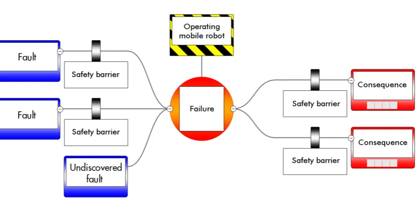
Fig. 3.1 Simplified bow-tie figure for most mobile robots.
Faults causing a failure (such as network interference causing a network connection error) are given on the left-hand side. Safety barriers try to prevent the failure from happening. These barriers can be as simple as voltage stabilizers or operators checking weather conditions. Not all faults have safety barriers preventing the failure. There likely are faults or failures that have not yet been discovered, and therefore do not have a safety barrier. In case these undiscovered faults occur, the failure and its consequences are imminent. As soon as any failure occurs, one of the consequences will follow, as there is no barrier to prevent this. For example, an unstable voltage source is afaultresulting in an onboard-computer failure (thefailure). The corresponding
safety barrierpreventing the failure could be a voltage stabilizer. Once the voltage stabilizer fails to stabilize the voltage, the onboard computer fails. This immediately results in one of theconsequences. For example, a flying mobile robot crashes in water and is lost.
3.1.1
Identifying onboard failures
What are common onboard failures? Some failures are identified because they happened before. Others because they were identified during discussions. Multiple controllers connected to one mobile robot can only cause a failure in a multi-robot environment. Currently, the identified onboard failures are:
• Onboard-computer failures • Motor controller failures • Network connection errors • Battery failures
• Multiple controllers • Incorrect output
3.1 What are common threats to deterministic behavior? 11
3.1.2
Analyzing onboard failures
Every onboard failure is analyzed and given a score for likeliness and consequence. The likeliness score goes from very unlikely to very likely in four steps. The likeliness is relative to one deployment of a mobile robot. The score for consequence goes from negligible to severe in four steps, describing the consequence to materials, environment, and humans. Many barriers are already implemented that lower the likeliness and consequence of onboard failures. These existing barriers (such as operators checking weather conditions) are included in the failure analysis.
Onboard-computer failures
When an onboard-computer failure occurs on the mobile robot, the operator experiences unexpected behavior. The mobile robot may do unexpected moves or come to a complete stop. In both cases, the mobile robot may cause damage, injuries or mission failures. There are many causes of onboard-computer failures. Electrical interference, bad programming, and hardware failures are some examples. With modern computers and programmers, onboard-computer failures are unlikely. Also, especially for operations by emergency services, extensive testing has been done to identify and resolve errors.
⇒Likeliness: unlikely
⇒Consequence: severe
Multiple controllers
In a multi-robot environment with multiple controllers, a mobile robot can potentially be linked to multiple controllers. This could lead to incorrect control signals and unexpected behavior. However, the combination of the control signals is not completely random and not necessarily problematic. The universal control system, developed at the University of Twente, gives exclusive ownership. This means – provided the multi-robot logic works properly – it is very unlikely that multiple controllers will be linked to one mobile robot.
⇒Likeliness: very unlikely
⇒Consequence: moderate
Network connection errors
Protection against network connection errors is especially required when a mobile robot is operating in a hostile environment. Mobile robots can often experience network connection errors. This can have multiple causes, depending on the communication protocol. Mostly, network connection errors occur because of a weak signal in certain locations. This results in the mobile robot showing unexpected behavior. It depends on the software what a mobile robot will do when the network connection is lost. Some are implemented in a way that the mobile robot will stop moving. Others will continue in the last known heading for a long period of time. Since operators are trained, they will take the range of a mobile robot in account when performing maneuvers. However, even then the mobile robot may lose signal due to obstructions or communicational noise. This gives a medium likeliness: possible. As mentioned, the consequences are significant.
⇒Likeliness: possible
Incorrect onboard computer output
An incorrect output by the onboard computer is an onboard failure that may lead to unexpected behavior. There are several causes that can lead to an incorrect output by the onboard computer. The most likely one is bad programming. Since mobile robots are extensively tested, the likeliness of incorrect onboard computer output is low. The consequences are high since arbitrary control signals or status parameters are produced. In turn, this may result in damage, injuries or mission failures.
⇒Likeliness: very unlikely
⇒Consequence: severe
Motor controller failures
Another onboard failure is a motor controller failure. This too can lead to unexpected behavior and uncontrolled mobile robots. In case the mobile robot is a flying mobile robot, it will crash unless the mobile robot is a multi-copter with more than four propellers. For the rover, the consequences are less severe than for a flying mobile robot. In case the mobile robot is a rover, the mobile robot will either come to a complete stop or start making turns in an arbitrary direction. Most motor controllers can handle faulty input values. However, the motor controllers may still fail due to noise or unstable voltage supplies. This makes the likeliness low. Since the consequences for flying mobile robots are severe, the consequence is considered significant.
⇒Likeliness: unlikely
⇒Consequence: significant
Battery failure
When the battery has failed, the mobile robot becomes dysfunctional. Communication is not possible and all motors will stop. For flying mobile robots this means falling to the ground. For mobile robots, this means coming to a complete stop, unless the mobile robot is positioned on a slope. Ideally, an operator knows the health of the battery. This can prevent battery failure. Nevertheless, humans make mistakes and battery failure may occur. The likeliness is low, but the consequence is high as all flying mobile robots will crash in case of battery failures.
⇒Likeliness: very unlikely
⇒Consequence: significant
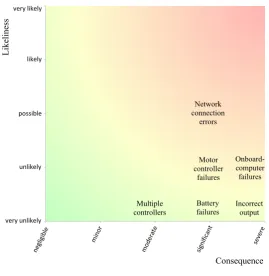
A common safety analysis technique used in critical chemical processes is setting up a risk matrix. In this matrix, the likeliness of every failure is plotted against the consequence of that failure. Multiplying the consequence with the likeliness gives the risk:
risk = consequence ∗ likeliness (3.2)
3.2 How can threats best be detected? 13 Onboard-computer failures Motor controller failures Network connection errors Battery failures Multiple controllers Incorrect output 1 2 3 4 5
1 2 3 4 5
[image:25.595.148.418.109.386.2]L ik el in es s Consequence likely possible unlikely very unlikely very likely
Fig. 3.2 Risk matrix.
From this graph, we can conclude that three failures (network connection errors, motor controller failures, and onboard-computer failures) pose the highest risk for normal operation of a mobile robot. Multiple controllers linked to one mobile robot is the least problematic failure. Every failure’s risk is determined to define an implementation priority. Barriers for all failures should be added to the safety layer.
3.2
How can threats best be detected?
This chapter describes the differences between fault detection and failure detection. Also, the detection logic location, the detection method, and the safety layer are described.
3.2.1
Fault detection
Table 3.1 Common computer failure causes. Category Fault Can result in
Bad programming
Buffer overflow
(Onboard-) computer
failure Integer overflow
Divide by zero Infinite loop
Deadlock Memory overflow Hardware Unstable voltage source
Poor assembly process Electrical noise Data corruption
The advantage of detecting faults on the onboard computer is that the onboard-computer failure can be prevented. Another advantage of detecting faults is that the fault resulting in the onboard-computer failure is known. This enables a fault specific solution which may save time. The disadvantage is that the entire state space of the faults (including unidentified ones) needs to be included. In other words, every possible fault needs its own detection logic. This means a failure in the onboard computer is not guaranteed to be detected. The large number of required safety barriers to detect every fault is another disadvantage.
3.2.2
Failure detection
3.2 How can threats best be detected? 15
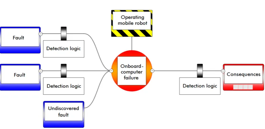
Fig. 3.3 Bow-tie figure showing fault detection (left-hand side) and failure detection (right-hand side).
Concluding, it costs a lot of effort and logic to detect faults resulting in a failure. Even when a fault is detectable, not all failures are detected due to undiscovered faults. Therefore, failure detection is much more fit for implementation.
3.2.3
Detection logic location
There are several locations for implementing detection logic. Traditionally, detection is done on the onboard computer, as it has access to all sensors and actuators. There are currently three locations where logic can be implemented that detects onboard failures. Detection logic can be implemented on the:
• Onboard computer • Network
• Controller (and operator)
Unfortunately, failures of the onboard computer cannot be solved by any of the three mentioned locations. This is because the onboard computer itself is dysfunctional and both the network and controller cannot access the mobile robot because there is no network connection with the mobile robot. To increase deterministic behavior of the mobile robots, onboard failures have to be included, especially considering its risk.
Independent safety layer
consequences – often by shutting down the process – and informs operators, who can trigger a reset of the process. The safety layer is independent of the control process, such that a failure in the latter does not affect the safety layer. It is important to note that this strategymitigatesfailures, meaning it keeps the consequences to a minimum, instead of preventing the failures. In the mobile robot industry, this concept can be a good solution for minimizing the consequences of onboard-computer failures. The independent safety layer can communicate with the onboard computer.
To make sure all onboard failures are mitigated, an independent safety layer must be added to the list of implementation locations. The safety layer is not integrated with existing logic, to ensure independence. The structure of the safety layer will be further described in 3.2.5. With this fourth location added, all onboard failures mentioned in 3.1.1 can be categorized.
Concluding, the onboard computer is capable of mitigating all onboard failures, except for one: onboard-computer failures. This must be done by the independent safety layer. The other onboard failures can best be implemented on the onboard computer. It already has access to all sensors and actuators. The network and controller both cover less onboard failures than the onboard computer. The overview of onboard failures and the corresponding location of the safety barrier is summarized in table 3.2.
Table 3.2 Onboard failures and their location for the safety barrier mitigating the failures. Onboard failure Safety barrier location
Onboard-computer failures Independent safety layer Motor controller failures Onboard computer Network connection errors Onboard computer Battery failures Onboard computer Multiple controllers Onboard computer Incorrect output Onboard computer
3.2 How can threats best be detected? 17
Fig. 3.4 Simplified bow-tie figure with the mitigating safety layer added.
3.2.4
Detection method
The best detection method must be determined. There are several methods for detecting onboard-computer failures. The control signals of the onboard computer can be monitored, the computer’s crash dump can be analyzed, a heartbeat signal can be added to processes or a watchdog timer can be used to monitor the system. The independent safety layer is responsible for detecting onboard-computer failures as it is the only entity capable of detecting them. The detection of all other onboard failures is done on the onboard computer.
Monitoring control signals
Every onboard computer used in a mobile robot outputs control signals. Using these control signals to detect onboard-computer failures leads to a universal safety layer. An onboard-computer failure can disrupt the control signals, which can be detected by the safety layer.
A test is done, to check if control signals can be used for detecting onboard-computer failures. A Raspberry Pi functions as the onboard computer outputting a PWM signal. The signals will represent a fixed value. A fork bomb will be performed on the Raspberry Pi, simulating an onboard-computer failure. At that point, a stopwatch is started. The safety layer is used to detect the absence of control signals. It reads the PWM signal and indicates a failure using light emitting diodes (LEDs) when the signal is different than expected. When the safety layer has detected the disruption, the stopwatch is stopped.
0 1 2 3 4 5
0 10 20 30 40 50 60 70 80 90 100 110 120 More
Co
u
n
t
Detection delay [s]
Fig. 3.5 Histogram of detection delay when using control signals as heartbeat.
One could argue that a change in control signals indicates the onboard computer is still active. However, this would mean that a mobile robot in normal operations has to keep altering its control signals. This is also not a feasible option since many operations require movements that have the same control signals for a long period of time. Therefore, a specific control signal for a long period of time cannot be interpreted as a failure in the onboard computer. Setting up a statistically acceptable set of rules for this would disrupt the functioning of either the safety layer or the mobile robot. Monitoring the control signals is not a suitable detection method for this safety layer.
Crash dump analysis
Many operating systems have a crash dump. After a failure, the system will write the cause of the failure to the crash dump log. Analyzing it is the most straightforward way of detecting a system failure and its cause. An advantage is that it is much easier to use this built-in logic, compared to manual monitoring of crash causes. The dump is usually flash memory or a local register to which the system writes failure information in case of a system crash. The safety layer can be given access to this memory and can therefore determine the cause of the computer failure, and indicate the failure. A disadvantage is that it is a slow detection method. Only after the system has failed, the crash dump has been produced and the crash dump is read, the failure will be detected by the safety layer.
3.2 How can threats best be detected? 19
Heartbeat signal
A heartbeat signal is a digital signal that is toggled periodically to show liveliness. This can be used for the onboard computer to signal the safety layer, even when the onboard computer has failed. When the toggling of the output is not observed for a number of time intervals, the onboard computer can be considered to have failed. The heartbeat signal is built-in to a process on the computer. The output of a heartbeat process is shown in figure 3.6.
10ms
0ms 20ms 30ms 40ms 50ms 60ms 70ms
Fig. 3.6 Output of a heartbeat process.
The process is responsible for toggling the heartbeat. This way, if a process is not responsive, it will not toggle the signal, which can be detected externally. The simple principle is beneficial for the implementation in various systems. However, the onboard computer may have independent processes running. One of the processes failing does not necessarily result in a system failure;process Amay have failed whileprocess B(containing a heartbeat process) is still functional. This issue can be prevented by implementing a heartbeat into every independent process. However – compared to one heartbeat process – this has a more complex implementation, requires more output pins and costs more computational load.
Testing the heartbeat timer is done by starting a process on the Raspberry Pi that toggles an output every 500 ms. A field-programmable gate array (FPGA) receives this signal and checks whether the toggles are at most 550 ms (allowing a 10% margin) apart. In case this deadline is not met, the onboard computer can be considered to have failed, illuminating an LED on the FPGA.
The results show, that a single heartbeat process (independent process on the onboard computer) is not capable of detecting failures of the onboard computer. The process has allocated memory, which it is given guaranteed access to. Even when a fork bomb is initiated, the single heartbeat process keeps properly toggling the output until the onboard computer shuts down as a result of overheating.
Watchdog timer
Bernard C. Drerup has designed a system crash detection and automatic resetting mechanism for processors [15]. These so-called watchdog timers are used to detect software crashes and quickly respond to it. The watchdog concept is shown in figure 3.7.
Computer
Watchdog (timer)
timeout reset
reboot
Fig. 3.7 The concept of a basic watchdog timer system.
Watchdog timers are commonly found in embedded systems. They are independent timers that are reset by the computer in case the watchdog’s internal tests are satisfactory. In contrast with the heartbeat signal, the input of the watchdog timer has no fixed period, only a deadline. The ability of the watchdog to test whether a predefined process is still running can be a powerful tool for the safety layer. The watchdog timer will only be reset in case all internal tests were successful. In case the computer fails to reset the watchdog – due to an internal error – the watchdog timer times out and initiates a system reboot. A sample watchdog signal is shown in figure 3.8. Note that the period of the watchdog signal is larger than the period of the heartbeat signal. This is because internal tests take time.
1s
0s 2s 3s 4s 5s 6s 7s
internal tests
OK
OK OK
internal tests internal tests
Fig. 3.8 Watchdog signal.
In mobile robots such as the Mars rover, the use of these watchdog timers is essential. A big advantage of a watchdog timer is that it monitors the status of the onboard computer. This means regardless of the cause, a failure in the onboard computer can be detected. The status is monitored by checking parameters such as network connectivity, memory, workload and CPU temperature. The watchdog system described above might need some modifications before it can be used in this research. The timeout signal from the watchdog timer must not immediately initiate a reboot of the computer. Instead, the timeout signal from the watchdog timer can be connected to the safety layer which in turn can have the ability to reboot the onboard computer.
3.2 How can threats best be detected? 21
an LED. A fork bomb is used to simulate an onboard-computer failure. Discontinuing the watchdog process must result in the safety layer detecting a failure.
From the results, I conclude that the watchdog timer is a reliable method for detecting onboard-computer failures, when the internal tests are carefully chosen. The timeout value (currently 1000 ms) also needs to be determined before implementation. It takes up to two seconds to detect an onboard-computer failure using a watchdog, as shown in figure 3.9. This means the onboard computer is still functional for at most one second after the fork bomb is initiated. The solution requires only one output pin and has a low CPU load. The results are summarized in table 3.3.
0 1 2 3 4 5 6
0 0.2 0.4 0.6 0.8 1 1.2 1.4 1.6 1.8 2 2.2 2.4 More
Cou
n
t
Detection delay [s]
Fig. 3.9 Histogram of detection delay when using a watchdog.
Table 3.3 Results of testing failure detection methods.
Single heartbeat process
Heartbeat process in every independent
process (P)
Standard watchdog timer
Monitoring control signals
Buffer overflow No Yes Yes No(1)
Integer overflow No(2) No(2) No(2) No(1)(2)
Divide by zero No Yes Yes No(1)
Infinite loop No Yes Yes No(1)
Deadlock No Yes Yes No(1)
Memory overflow No Yes Yes No(1)
Data corruption Not tested(4) Not tested(4) Not tested(4) Not tested(4)
Unstable voltage source No(3) No(3) No(3) No(1)(3)
Poor assembly process Not tested(4) Not tested(4) Not tested(4) Not tested(4)
High load (overheat) No Yes Yes No(1)
CPU load ~0% ~0*P% ~0% 0%
Pin count 1 P 1 0
(1)Until absence of control signals.
(2)Integer overflow is impossible in Python, provided there is enough memory.
(3)Until voltage source unacceptably low.
(4)Data corruption and poor assembly process are complex to reproduce.
3.2 How can threats best be detected? 23
3.2.5
Safety layer structure
The safety layer can only be independent if it is stand-alone. This means it will not be integrated with existing logic, such as the onboard computer. A stand-alone solution can be implemented locally (on the mobile robot) or remotely. Kristen Anderson’s research [16] shows a proof-of-concept for a crash avoidance system on a toy car. A remote safety layer functions using sensor data transmitted from the car. The remote solution works as a safety layer in the proof-of-concept. However, when a loss of connection to the sensors occurs, the crash avoiding safety layer cannot function. A remote solution is not feasible, because a network connection with the mobile robot at all times cannot be guaranteed. Hence, a local stand-alone solution is required.
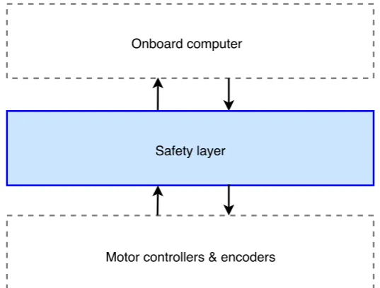
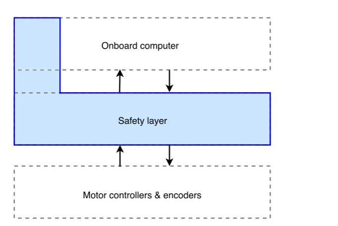
Ideally, the safety layer is implemented between the onboard computer and the motors of a mobile robot since it can then interrupt control signals when necessary. This implies that the watchdog is also implemented on the stand-alone safety layer. This is shown in figure 3.10. Also, it does not have logic on the onboard computer or motors which ensures simple and generic installation.
Safety layer
[image:35.595.170.439.311.515.2]Motor controllers & encoders Onboard computer
Fig. 3.10 Ideal structure of the safety layer, ensuring a generic solution.
This would mean a generic solution has been found which can be implemented on any mobile robot. The scenario from figure 3.10 is only possible if no logic has to be added to the onboard computer or to the motor controllers & encoders. This logic does not have to be added when the onboard computer’s control signals can be used as a way of detecting onboard-computer failures.
Safety layer
[image:36.595.146.488.91.319.2]Motor controllers & encoders Onboard computer
Fig. 3.11 Revised structure of the safety layer.
The external logic has the advantage of being independent of the mobile robot’s main logic. This means a malfunction in the main logic does not interrupt the performance of the safety logic. The combination of internal and external enjoys the advantage of flexibility. The internal logic has access to all sensors, parameters and other logic on the mobile robot. This internal logic can communicate with the external logic which on its turn is independent of the main logic. A disadvantage is that the internal logic is unresponsive in case of onboard-computer failures. Another disadvantage is extra financial and physical space costs for external logic. Access to the onboard computer of the mobile robot is necessary for the watchdog to function. This is impossible without integrating the detection logic on the mobile robot. Hence, the safety layer must contain logic integrated on the onboard computer. The safety layer must be able to function stand-alone in case the onboard computer shows severe failures. In that case, the detection logic will be unresponsive. This conclusion means sacrificing some physical space on the mobile robot. Altogether, the safety layer will be astand-alone onboard solution. It has a watchdog on the onboard computer and all other logic on the external safety layer.
3.3 What is the appropriate response to failures? 25
3.3
What is the appropriate response to failures?
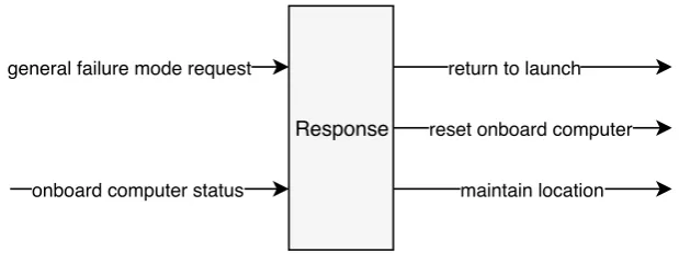
The safety layer is responsible for responding to onboard-computer failures. In case of any other onboard failure (general failures), the safety layer’s only response is to keep the mobile robot in its current location. These failures are given further response by the onboard computer. A response that matches the operator’s expected response should be determined to increase deterministic behavior. What should the safety layer’s response to onboard-computer failures be?
3.3.1
Proposed response
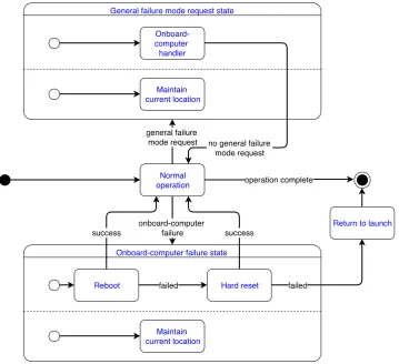
The initial response by the safety layer must be to keep the mobile robot in its current location. Maintaining location includes altitude in case of a flying mobile robot. If critical processes (such as the control process or the video process) are not responding, these processes must be restarted. In case the network connection has failed, a restart of the network interface must be performed. If these actions are not successful, a reboot of the onboard computer must be performed. A reboot (soft reset) must always be attempted before a hard reset is performed. Mission data can be lost when rebooting the onboard computer. Hence, backing-up and recovering mission data must be considered. Mission data can be stored in arbitrary locations, with any data size and structure. Making a back-up or recovering these files can be complex. If a hard reset is not successful, there is no other option then to return to launch using the safety layer. If the onboard-computer failure is solved, and the control has been recovered, the mobile robot can continue operations.
3.3.2
Resetting the onboard computer
Resetting the onboard computer is an essential function of the safety layer. There are two options for resetting the safety layer: a reboot and a hard reset. A reboot gives the onboard computer the reboot signal. This is the safe way of rebooting a system. It initiates a sequence of commands that prevents system corruption. The system is given time to save important data to memory, unmount external drives and eventually perform a reboot. A hard reset is the last measure against unresponsive systems. Data corruption may occur, and important data may be lost. A hard reset cuts the power to the system and reboots it.
3.3.3
Configuring the response
To increase deterministic behavior of mobile robots, the operator’s expected response must match the mobile robot response. The operator’s expected response may differ per operator and mission. Therefore, the operator must be given the ability to configure the safety layer’s response. Parameters such as the timeout value for the mobile robot to return to base instead of solving the failure must be configurable.
3.4
How can the responses best be effectuated?
With the responses determined, effectuating the responses can be analyzed. The safety layer should be able to keep the mobile robot in the current location, reset the onboard computer and guide the mobile robot back to the launch location.
3.4.1
Timing requirements
What are the timing requirements for the safety layer? Immediate detection of onboard-computer failures is valuable. However, false positives must be prevented. A quick response by the safety layer will be beneficial for the system performance. Computational deadlines for producing the control signals must be met to ensure smooth control over the mobile robot.
Detection
Instantly detecting abnormal behavior using the watchdog is valuable. However, the safety layer must always be sure that abnormal behavior is actually occurring, when it indicates a failure. Falsely activating the safety layer costs time and can impact emergency operations. The effects of these false positives can be as big as not activating the safety layer after actual failures. On the other hand, faster detection of failures is beneficial for the overall performance of the safety layer. The outcome of several internal checks determines whether the onboard computer is in normal operations or if there is an onboard-computer failure. The internal checks can be:
• Is there enough free memory? • Is the average CPU load acceptable? • Is the video process still running? • Is the control process still running? • Do network interfaces receive traffic? • Is the CPU temperature acceptable?
By observing these parameters before and during onboard-computer failures, a selection is chosen for the design. The free memory is a good parameter to check. Under normal operations, an onboard computer uses no more than 80% of its memory. This is an observation and depends on the hardware. The workload is not a reliable parameter to monitor. A peak in user requests can trigger a CPU load of 100% which does not represent a failure. Monitoring the video process and the control process are valuable internal tests for the watchdog. A failure in one of these processes represents a failure. Network connectivity is currently not a good parameter to check. The Raspberry Pi has a weak wireless local area network (WLAN) adapter, occasionally causing network interruptions. This can lead to false positives. The CPU temperature is a suitable parameter to monitor. From observation, I concluded that the CPU temperature does not exceed 85 °C under normal circumstances. Only in case of failures, the CPU temperature is higher.
3.4 How can the responses best be effectuated? 27
detection of failures. A Raspberry Pi is used as an onboard computer. The amount of false positives depends on the timeout and the CPU load. CPU loads of 30%, 50%, 70%, and 90% are tested for timeouts between 100 ms and 2000 ms. The load is kept constant at the desired level by dummy processes that rapidly perform complex calculations. The safety layer keeps count of the number of onboard-computer failures it has detected. The results are shown in figure 3.12.
0 100 200 300 400 500 600
0.1 0.2 0.3 0.4 0.5 0.6 0.7 0.8 0.9 1.0 1.1 1.2 1.3 1.4 1.5 1.6 1.7 1.8 1.9 2.0
False po sitiv e s [m in -1]
Watchdog timeout [s]
90% load
70% load 50% load 30% load
Fig. 3.12 Results of the watchdog timeout test.
False positives are unacceptable. Therefore any timeout lower than 1100 ms cannot be used. Even though it comes at the cost of a larger detection delay, I assume a timeout of 1500 ms is an acceptable compromise. This means it takes up to 1.5 seconds to detect an onboard-computer failure.
Response
After an onboard failure has been detected, the safety layer needs to produce appropriate control signals as fast as possible. Producing computational results such as control signals too late will negatively impact the performance of the safety layer. The safety layer can always produce control signals that try to keep the mobile robot in its current location. Up to the point where an onboard-computer failure is detected, these control signals will be ignored. This yields a quick response.
Concluding, the detection is done by a watchdog timer with a timeout value of 1500 ms, this ensures a low probability of false positives and a quick detection of failures. The responses must be produced immediately after an onboard-computer failure is detected. This is done by continuously producing control signals that try to keep the mobile robot in its current location. They are not propagated until an onboard-computer failure is detected.
Safety layer
The response must be produced by the safety layer as fast as possible. The safety layer can have three different timing requirements: soft real-time, firm real-time or hard real-time.
simple implementation because of the widely available reference material. Basic (high level) code and a basic microcontroller unit (MCU) can satisfy soft real-time requirements. A disadvantage is that the quality of the produced signals is low. A PWM signal produced in a soft real-time environment will show deviating values over time as deadlines are missed repeatedly. This is because the design focus is not on timing.
In firm real-time systems, incidentally missing a deadline is acceptable, though its computational results are useless. Producing results after the deadline therefore only degrades system performance. This means the system is designed to perform all calculations within the given deadlines. The advantage of such an environment is its implementation. Most MCUs running standard quality code can satisfy the firm real-time requirements. The disadvantage is that not all computations are guaranteed to be performed within their given deadline. In hard real-time systems, missing a computational deadline has catastrophic consequences. A hard real-time environment guarantees that all computational deadlines will be met. This comes at the cost of complexity. This disadvantage means only the most powerful devices and expert coding skills can be used to satisfy hard real-time requirements. Designing hard real-time systems requires a complex timing and system analysis. Concluding, the safety layer is a real-time system as the correctness of the system depends not only on the logical results of the computation, but also on the computational time. The safety layer should be afirm real-time system. Missing some deadlines can be afforded, although it degrades system performance. The design focus must be on meeting computational deadlines. Soft real-time systems are not quick enough, as deadlines are missed repeatedly. Hard real-time systems have excessively high timing requirements.
3.4.2
Logic implementation
There are three options for implementing the firm real-time safety layer. First, it could be implemented in software which sequentially executes code. Second, the safety layer logic can be implemented in hardware on a printed circuit board (PCB). A third option is using an FPGA, in which logic gates can be programmed to form a hardware circuit.
3.4 How can the responses best be effectuated? 29
A third option is to use an FPGA, in which hardware can be programmed to show desired behavior. The programmable hardware circuit allows a lot more flexibility compared to a hardware implementation on a PCB. FPGAs translate VHDL code to a hardware circuit. This implies a parallel execution of desired behavior. FPGAs can also execute statements sequentially using processes. In a process, sequential statements such as conditional logic can be used. This simplifies the implementation of for instance a GPS sensor. Justin Young researched the benefits of controlling a quadcopter using an FPGA instead of an MCU [17]. He concludes that it is feasible to make a light-weight controller for quadcopters. When using an FPGA, more room is left-over for advanced features because the processor is free of data gathering activities thanks to the parallel nature of FPGA design.
Concluding, functionalities implemented using hardware provide a faster solution, satisfying firm real-time requirements. As some functionalities such as GPS or reading sensors require sequentiality, a hardware-only solution is infeasible. An FPGA allows reprogramming and sequential processes; this offers flexibility and simplicity, while still satisfying firm real-time requirements. A software solution provides the necessary flexibility and simplicity but does not always satisfy firm real-time requirements. An implementation using an FPGA is a more lightweight solution, satisfying firm real-time requirements. Therefore, an FPGA will be used. The watchdog is implemented on the onboard computer, as concluded in section 3.2.5. Its timing environment is constrained by the onboard computer.
3.4.3
Power supply
A safety layer must be active when the mobile robot is active. This is to ensure that the safety layer can perform its tasks. Providing power to the safety layer can be done by connecting it to the main battery, by giving it a separate battery or by implementing a resettable fuse to the onboard computer.
The safety layer can be powered by the mobile robot’s main battery. The advantage is no additional financial and physical space costs. The solution provides power to the safety layer when the mobile robot is functional. A disadvantage is that power must be shared with the onboard computer, which might be problematic. An onboard malfunction could result in a short circuit or high load at the onboard computer. This can leave too little power for the safety layer to function. Until the malfunction of the onboard computer is fixed by the safety layer, there will be no power left for the safety layer.
The safety layer can also be powered by a separate battery. This ensures the safety layer is always active. A disadvantage is that the separate battery must always have sufficient charge. This can be realized by charging the separate battery with the main battery. This means additional logic has to be added. Another disadvantage is the additional physical space and financial cost of the battery.
Concluding, a mobile robot will not be able to perform any actions requested by the safety layer when the mobile robot’s battery is dead. In that case, it is useless to have an active safety layer. Hence, there is no need for an additional power supply for the safety layer. A resettable fuse to the onboard computer will guarantee access to the main battery for the safety layer. The resettable fuse cuts off power to the onboard computer when its load is too high. However, since all certified onboard computers have a fuse already, the onboard computer will already switch off or reboot when the power consumption is abnormally high. Therefore, the safety layer will be powered by the mobile robot’smain battery. This will guarantee an active safety layer when the mobile robot is active.
3.4.4
Access to sensor data
Mobile robots need to be able to return to launch and need to be able to stay in the current location. In case of a rover, staying in the current location means compensating for unwanted movement due to slopes. In case of a flying mobile robot such as a multi-copter, this means compensating for wind and natural drift in all six degrees of freedom. The only data necessary for maintaining location isrelative location data. Returning to launch requires eitherabsolute location dataor relative location data and recording the traveled path. For recording the traveled path, an accelerometer or optical flow sensor are possible. The disadvantage of an accelerometer is that it may fail to detect a velocity offset as it only senses acceleration. The disadvantage of using an optical flow sensor is that it has to be mounted on the mobile robot, such that it can determine flow. For most mobile robots that would be facing the ground. Another disadvantage of the optical flow sensor is that it cannot measure altitude. A GPS can be used to find the absolute location. Then, there is no need for recording the traveled path. The disadvantage of GPS is that it does not always work indoors. Abdulqadir Alaqeeli researched the implementation of a fast GPS position tracking system on an FPGA [18]. The results were satisfactory: the number of operations was reduced, the hardware implementation was simplified and the acquisition time was decreased. Access to sensor data can be given by sharing sensors with the onboard computer or by giving the safety layer private sensors.
The safety layer can use the mobile robot’s onboard sensors to control the mobile robot. To ensure functionality even when the onboard computer is dysfunctional, the sensors will require rerouting and data sharing. This is a disadvantage when implementing a safety layer and is in some cases even impossible, for instance when the GPS is embedded on the onboard computer. An advantage of sharing sensor data is that it does not have any extra financial or physical space costs. The safety layer can also be given its own sensors. This would allow a universal safety layer for all mobile robots. The disadvantage, however, is that it will introduce extra financial and physical space costs. The advantage is always functional sensors for the safety layer.
3.4.5
Control signals
3.4 How can the responses best be effectuated? 31
The safety layer must be able to switch between control signal sources. The two sources are the onboard computer and the safety layer. There will be a phase difference between the control signals of the onboard computer and the control signals of the external safety layer because they have a separate clock. To ensure both the onboard computer and the safety layer can provide control signals, they need to be in phase. Otherwise switching between control signal sources can cause motor controller failures. The multiplexer reads the incoming control signals and reproduces them in phase with the safety layer’s control signals. This ensures smooth transitions between control signal sources. Note that this introduces a permanent delay between the control command and control action. The maximum delaydmax, as seen in equation 3.3, is the multiplicative
inverse of fc; the control signal frequency. As this frequency is generally 50 Hz,dmaxis generally 20 ms.
dmax=
1
fc
(3.3)
3.4.6
Autonomously maintaining location
Lachlan K. Scott researched autonomously hovering drones by means of vision-based flight control [19]. This method used the device’s camera to anchor the drone to a location. The research successfully created a system that eliminated natural drift of a drone. This has been tested outdoors in light winds and indoor on a treadmill. One problem encountered in the research is the next: "However with the low frame rates and resolution available using the AR Drone, it was unable to achieve autonomous hover when there was a lack of well-defined features such as over-well-kept lawn or during low light conditions" [19]. In that case a gust of wind will cause the drone to lose its anchor. Overall, the research for autonomous hovering was successful. One remark is that the researchers used a camera. Optical flow sensors outputting a velocity vector were not considered. This sensor may be cheaper and more sophisticated than using a general purpose camera. However, autonomously maintaining the current location can be done using different techniques too. What are the options?
Accelerometer
An accelerometer can measure acceleration in the three-dimensional space. By integration, the velocity and distance can be calculated. With the accelerometer, the acceleration ak(t)in directionk∈[x,y,z]can be
determined. As seen in equation 3.4, integrating this can yield the velocity. However, the initial velocityv0,kis
unknown. This causes a constant velocity offset.
vk(t) =v0,k+
Z t
0
ak(t)dt (3.4)
When trying to keep a mobile robot in its location, the velocity is not enough. The displacement has to be calculated. This is done by integrating the velocity in directionk, as shown in equation 3.5. Note that the velocity offset is integrated too. An additional offset is added: initial positionx0,k. When trying to keep a
mobile robot in its current location, this can be set to zero as a relative location is sufficient.
xk(t) =x0,k+
Z t
0 [v0,k+
Z t
0
It could be that the offset is negligible. When the acceleration is in the formak(t) =b+ct+dt2, the relative
location of the mobile robot to an anchor location can be described. Equation 3.6 describes this relative location. The termsb,c, anddare measured by the accelerometer. However,v0,kis unknown. When integrated, the drift
v0,k(t)is introduced, growing over time. This means the offset is not negligible.
xrel,k(t) =v0,kt+b
t2
2 +c
t3
6 +d
t4
12 (3.6)
The disadvantage of using an accelerometer for keeping a mobile robot in its location is the velocity offset, which causes a displacement drift. The advantage of using an accelerometer is its low complexity, low physical space cost and low financial cost of implementation.
Optical flow sensor
An optical flow sensor is a camera with the sole purpose of outputting a two-dimensional velocity vector. The camera finds points that it recognizes and checks the location of those points in every frame. The displacement of the points determines the velocity magnitude and direction. This can be used to anchor a mobile robot to a location. The advantage is that – provided the surface is satisfactory – the technique works accurately, without an offset, also indoors. There are some disadvantages to this technique. First, when the camera has little to no points to recognize, the sensor fails to output a velocity vector. This may be a problem in some terrains or poor lighting conditions. Second, the optical flow sensor needs to be mounted on the outside of a mobile robot, facing the surface it moves along. This may not always be feasible. Finally, the optical flow sensor is two-dimensional. It does not take altitude into account. This is a problem for flying mobile robots. The optical flow sensor can be implemented alongside a barometer measuring altitude. Even then, some of the mentioned disadvantages persist.
GPS
A GPS receiver uses trilateration to find its absolute location. This is done using satellites orbiting earth as references. Finding the location is a relatively complex computation. However, since it is a very popular concept, reference material is available. The advantage of using a GPS is the absolute location it yields. This means no offsets or drifts. The disadvantage is that the receiver should have access to satellite data. This is not always the case indoors.
Compass
The mobile robot needs to know its orientation in order to be able to go to any predefined location. This is a requirement for the maintain current location command. An electronic compass can provide this information to the safety layer.
3.4 How can the responses best be effectuated? 33
location of the mobile robot is provided. The absolute location provided by a GPS sensor is more reliable and therefore the better choice. Absolute location data eliminates drift of the mobile robot. A GPS sensor does not always work indoors.
3.4.7
Return to launch
Accelerometer
Returning to launch can be done using an accelerometer when the traveled path is recorded. The accelerometer is capable of capturing the mobile robot’s displacement information. However, the earlier discussed displacement drift is a major disadvantage. It will make safely returning to launch using an accelerometer unlikely. Additional sensors are needed to find the altitude of the mobile robot.
Optical flow sensor
Returning to launch can also be done using an optical flow sensor when the traveled path is recorded. The optical flow sensor is capable of capturing the mobile robot’s displacement information too. However, it is not capable of capturing the mobile robot’s altitude data. A lack of well-defined features on the ground may cause errors in the mobile robot’s path to launch. The optical flow sensor must be mounted in an appropriate location, which introduces an additional disadvantage.
GPS
The mobile robot can return to launch using a GPS sensor. Finding the absolute location minimizes errors, as corrections are constantly performed. Waypoints to the location of the launch can be used to guide the mobile robot back to launch. A disadvantage is that the GPS may lack access to satellite data indoors.
Compass
The mobile robot needs to know its orientation in order to be able to go to any predefined location. This is a requirement for the return to launch command. An electronic compass can provide this information to the safety layer.
4
|
Design & implementation
How can the safety layer be implemented most effectively? This chapter describes the design of the safety layer, based on the conclusions of chapter 3. Of every component the design is discussed, followed by its implementation. The overview of the system components is described first.
4.1
Overview
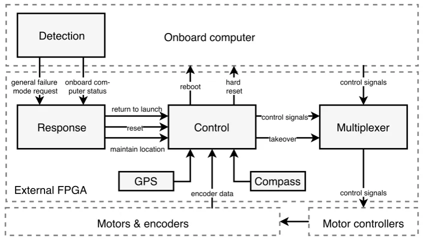
As described in the analysis chapter, the functionalities of the safety layer are to detect failures, respond to failures and to conditionally take over control of the mobile robot. Additionally, the safety layer needs to be able to switch between control signals. Therefore I propose a safety layer consisting of four components: a
detection block, aresponse block, acontrol block, and amultiplexer. The blocks are shown in figure 4.1. The control block requires sensors. Details about the functionalities, connections, and implementations of every block are described next.
control signals
takeover hard
reset reboot
encoder data
Control
resetmaintain location return to launch
Response
onboardcom-puter status
Detection
Onboard computer
Motors & encoders
External FPGA
general failure mode request
control signals
control signals