warwick.ac.uk/lib-publications
Original citation:
Beckingsale, David A., Gaudin, W. P., Hornung, R. D., Gunney, B. T., Gamblin, Todd, Herdman, J. A. and Jarvis, Stephen A. (2014) Parallel block structured adaptive mesh refinement on graphics processing units. Lawrence Livermore National Laboratory. (LLNL Technical Report).
Permanent WRAP URL:
http://wrap.warwick.ac.uk/90866
Copyright and reuse:
The Warwick Research Archive Portal (WRAP) makes this work by researchers of the University of Warwick available open access under the following conditions. Copyright © and all moral rights to the version of the paper presented here belong to the individual author(s) and/or other copyright owners. To the extent reasonable and practicable the material made available in WRAP has been checked for eligibility before being made available.
Copies of full items can be used for personal research or study, educational, or not-for-profit purposes without prior permission or charge. Provided that the authors, title and full bibliographic details are credited, a hyperlink and/or URL is given for the original metadata page and the content is not changed in any way.
A note on versions:
The version presented in WRAP is the published version or, version of record, and may be cited as it appears here.
LLNL-TR-664446
Parallel Block Structured
Adaptive Mesh Refinement on
Graphics Processing Units
D. A. Beckingsale, W. P. Gaudin, R. D. Hornung,
B. T. Gunney, T. Gamblin, J. A. Herdman, S. A.
Jarvis
Disclaimer
This document was prepared as an account of work sponsored by an agency of the United States government. Neither the United States government nor Lawrence Livermore National Security, LLC, nor any of their employees makes any warranty, expressed or implied, or assumes any legal liability or responsibility for the accuracy, completeness, or usefulness of any information, apparatus, product, or process disclosed, or represents that its use would not infringe privately owned rights. Reference herein to any specific commercial product, process, or service by trade name, trademark, manufacturer, or otherwise does not necessarily constitute or imply its endorsement, recommendation, or favoring by the United States government or Lawrence Livermore National Security, LLC. The views and opinions of authors expressed herein do not necessarily state or reflect those of the United States government or Lawrence Livermore National Security, LLC, and shall not be used for advertising or product
endorsement purposes.
Parallel Block Structured Adaptive Mesh
Refinement on GPUs
D. A. Beckingsalea,∗ W. P. Gaudina R. D. Hornungb B. T. Gunneyb T. Gamblinb J. A. Herdmana
S. A. Jarvisa
aAWE, Aldermaston, UK
bLawrence Livermore National Laboratory, Livermore, CA, USA
Abstract
1
Introduction
Block-structured adaptive mesh refinement (AMR) allows for fewer resources to be used to achieve the required accuracy in interesting areas of a problem [4, 5]. These areas of interest (shock fronts, material interfaces, etc.) are refined, and recursively covered with rectangular patches of computational mesh at a higher resolution. The patches are grouped into a hierarchy of levels of refinement that dynamically adapt throughout the computation as the areas of interest move. De-spite the potential for large savings in resource usage with maintained accuracy, AMR requires dedicating a portion of application runtime to managing the mesh hierarchy; this requires complex data management and communication.
Most AMR applications run exclusively on the CPU, and those that do use GPUs often copy the necessary data between GPU and CPU memory at the be-ginning and end of every GPU-based routine [14, 16, 20]. We present a native
implementation of AMR on GPUs. Building on the SAMRAI framework [2], we create classes that manage the life cycle of AMR patches where data is stored ex-clusively on the GPU. All routines that manage the patch hierarchy continue to be handled by SAMRAI on the CPU, but all AMR-specific routines that operate on patch data, such as the coarsening and refining of data between adjacent levels in the hierarchy, execute on the GPU.
Using the object-oriented interface of SAMRAI we develop a set of routines and data structures that allow patch-based data to reside on and be manipulated by the GPU. Using these extensions we write a GPU-based AMR hydrocode, Clev-erLeaf, that performs up to 4.87×faster than the CPU-based implementation on a single node, and has already been scaled to four thousand nodes using a com-bination of MPI and CUDA. We describe the design and implementation of our GPU-based AMR library extensions in this paper, including the classes used to manage patch data, the routines used for transferring data between GPUs on dif-ferent nodes, and the data parallel operators developed to coarsen and refine mesh data. We also validate the accuracy of our implementation on three test problems, and present performance studies using up to 4096 NVIDIA K20x GPUs.
2
Background and Related Work
..
(a) Simple adaptive mesh, where each grid patch has a thick outline.
...
G0 .
G1 .
G2
(b) Full hierarchy of three grid lev-els for the simple mesh.
Figure 1: Example adaptive mesh and corresponding grid hierarchy.
2.1 Adaptive Mesh Refinement
Adaptive mesh refinement uses a hierarchy of nested, logically rectangular grids over which the partial differential equation being solved is discretised. As in Berger et al. [4, 5], we provide a formal notation for our hierarchy in terms of these grids. The coarsest grid is the base grid, specified at the start of the computation and de-notedG0. It may be composed of several possibly overlapping patches. This base
grid remains fixed throughout the simulation. Each component patch is denoted
G0,j, and thusG0is the union of its componentsG0,j:
G0 =∪jG0,j (1)
During the simulation, refined sub-grids of patches will be created in response to features in the solution. Sub-grids are not placedinthe coarse grid, but on top of it. Each sub-grid is defined independently and has its own solution vector, and can be advanced almost independently of all other grids. These independent grids provide a natural method of domain decomposition allowing for easy parallelisation of the algorithm.
Fine sub-grids can contain finer sub-grids within their boundaries. Sub-grids are recursively generated to provide the necessary level of refinement, creating a hierarchy of grid levels. The coarse gridG0is at level 0 in the hierarchy. Sub-grids
ofG0are part ofG1and are described as level 1 refinements. Refined grids within
G1are at level 2. A nested sequence of sub-grids may be created to cover a portion
of the domain. Figure 1 shows an example hierarchy containing three grid levels. The mesh spacing, or resolution,hlfor each grid levellis normally specified
in advance, where eachhlis an integer multiple ofhl−1. The relationship between
the mesh spacing at each level is typically specified as the refinement ratio:
rl=
hl−1
hl
Grids at different levels of the hierarchy must be properly nested. A fine grid must start and end at the corner of a cell in the next coarser grid, and there must be at least one levell−1cell separating a grid cell at levellfrom a cell at levell−2in any direction unless the cell is at the physical boundary of the domain. The proper nesting requirement does not require a fine grid to be contained in only one coarse grid, so one fine grid may be nested in two or more coarser grids.
The AMR algorithm has three main components: (i) advancing the simulation using some finite difference scheme, (ii) error estimation and hierarchy generation, and (iii) inter-level operations such as solution projection and the filling of patch boundaries. These procedures are interleaved to correctly and conservatively ad-vance the simulation on the adaptive hierarchy. When the simulation is initialised, the error estimation and hierarchy generation procedure must be used to generate the hierarchy, since only the coarsest level is specified by the user. Once the hi-erarchy is created, the main loop of the simulation proceeds as follows: first, the boundary conditions of each patch are filled; second, the simulation is advanced in time using the integration algorithm; third, the error estimation and hierarchy generation procedure is used to update the simulation grid.
Each patch will require some data to be placed in additional cells around the patch edge to provide boundary conditions for the system of partial differential equations. Boundary data for each patch can be filled in one of three ways: (i) with the physical boundary conditions, (ii) with the data from a neighbouring patch on the same level, or (iii) with the data from a neighbouring patch on the next coarsest level. When data is transferred between levels it must be interpolated to correctly fill the increased number of smaller cells on the finer level.
Since each patch is defined as an independent computational entity with its own solution storage, each patch can be integrated in time independently once its boundary values are supplied. This independence means that, using the patch as a basic unit of work in the simulation, work can be easily shared between multiple processes. The solution on a patch is modified in the case when a cell is covered by a fine grid, and the coarse cell value is replaced by a conservative average of the fine cell values that cover the coarse cell.
At the beginning of the simulation, and with a given frequency, an error estima-tion procedure is invoked to determine the structure of the patch hierarchy. When more than one level of patches exists, the procedure is applied recursively from the second finest to the coarsest level of the hierarchy. This regridding procedure has three steps: flagging, where a heuristic is applied to determine which levellcells ought to be covered by the levell+1patches; clustering, where the new set of level
(boundary value determination, integration, and regridding) are repeated until the end of the simulation.
2.2 Programming Models for Graphics Processing Units
Programming for GPUs requires the use of a programming model such as CUDA, OpenCL, or OpenACC. For this work, we use NVIDIA’s CUDA programming model, as it is the most mature and feature-rich model for programming NVIDIA hardware. GPU functions are written askernelswhich are executed simultaneously in a single-instruction-multiple-data (SIMD) fashion on the device. A CUDA-capable GPU is a collection of stream multiprocessors (SMs), consisting of a num-ber of stream processors (SPs) that share an instruction cache.
The CUDA programming model revolves around the concept of threads, blocks, and grids that execute on these hardware units. A thread executes on a single SP, and blocks are groups of threads that are mapped to SMs and will execute concur-rently. A grid is a collection of thread blocks, typically dependent on the size of the data being maninpulated. The grid can be either one- or two-dimensional, and defines the total index space for the threads. These grids are used to map threads onto portions of the application domain. When a device kernel is launched, each thread runs one instance of the kernel. The co-ordinates of a thread can be accessed inside the kernel, allowing each thread to determine which elements of global data to process.
OpenCL uses a similar programming model to CUDA, with GPU functions being written as kernels that will be executed in parallel on a given device. The OpenACC model is different, having more in common with OpenMP. It relies on source code annotation using directives to mark regions of code for execution on the GPU. The use of CUDA in our work is an implementation detail, and the techniques we apply would map equally well to OpenCL and OpenACC.
2.3 Adaptive Mesh Refinement with Graphics Processing Units
Berger’s adaptive mesh refinement algorithm was presented in 1984, and many computational physics codes have been ported to GPUs since the release of CUDA in 2007. However, there is little work where AMR codes have been ported to GPUs. We suppose that this is due to the large amount of data management required when updating the adaptive hierarchy, and the fact that na¨ıve method for porting codes to GPUs revolves around repeatedly copying simulation data to and from the GPU across the slow PCI bus.
Runge-Kutta kernel used to advance the solution, the required data must be copied from the CPU to the GPU. This basic implementation achieves a 10x speedup over a single CPU core, although with today’s supercomputer nodes typically having at least 16 processor cores, this number is not high enough to make this method useful.
In [6] the authors briefly describe a forest-of-octrees based AMR algorithm for seismic wave propogation on GPUs. The implementation doesn’t appear to be native, as although the text lacks sufficient details about the GPU-based implemen-tation, the results presented include timings for transferring the mesh and initial data to the GPU from the CPU memory. Nevertheless, the parallel performance of the code is scalable on up to 256 GPUs.
Schive et al. introduce GAMER, an astrophysical simulation code with both AMR and GPU support [17]. Both the Eulerian hydrodynamics and self-gravity phases of the application are solved on the GPU, but the necessary data is stored in the CPU memory, and must be transferred to the GPU memory before the compu-tational kernel is launched. The data transfer is performed concurrently with other computation, so the imapact is minimised, and the authors note that data transfer time typcially only takes 30% of the application runtime. The Uintah framework from the University of Utah is an AMR framework that supports GPUs [11, 14]. The focus in Uintah is on heterogeneous platforms, and as with GAMER, solution data must be copied between the CPU and GPU memory as required by the numer-ical kernels. These data transfers are overlapped with other work, but nevertheless, this is not a fully native framework.
Shamrock is an Eulerian hydrodynamics code with AMR, similar to Clever-Leaf, that supports exectution on GPUs via OpenCL [9]. Only a small fraction of the necessary methods are ported to the GPU, and data is again copied between the CPU and GPU memory at the beginning and end of the four routines that are ported. As is to be expected, the performance of the GPU-based routines was bet-ter than the CPU-based equivalents when data transfer time was excluded. Using a simple performance model and the application of Amdahl’s law, the authors predict an order of magnitude speed up if 95% of the application is ported to the GPU and data transfer only occurs at the start and end of the simulation.
The CLAMR application developed at Los Alamos National Laboratory is a cell-based AMR code that solves the shallow-water equations [15]. Implemented in OpenCL, the codeisnative; initial conditions are set on the CPU and then copied to the GPU memory at that start of the simulation, but data is not copied back to the CPU during the simulation timestep. The cell-based scheme is different to the block-structured approach described by Berger and used in our work.
Patch
Box
(1,1)
(4,4)
Array<PatchData>
PatchData
copy() packStream() unpackStream()
CudaArrayData
double* d_cuda_buffer;
CudaCellData
CudaArrayData* d_array_data;
CudaNodeData
CudaArrayData* d_array_data;
CudaSideData
[image:10.612.155.457.130.224.2]CudaArrayData* d_array_data;
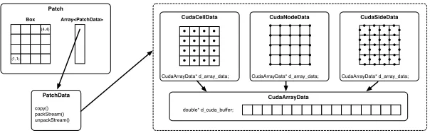
Figure 2: Class relationships for the CudaArrayData-based datatypes.
shallow-water equations. The authors take a similar approach to our library and ensure all computationally expensive parts of the AMR library are handled on the GPU, and they demonstrate performance improvements of up to3.4×compared to a uniform GPU-based implementation of the same algorithm. Despite the similar-ities to our work, the domain (shallow-water equations) is different, and this work remains unpublished.
To the best of our knowledge we have developed the only native GPU-based shock hydrodynamics code with AMR. Furthermore, by developing the necessary code as part of the SAMRAI library, we provide a collection of components that can be re-used in other block-structured AMR applications.
3
Design and Implementation
The SAMRAI library uses object-oriented design patterns to allow for easy inter-action with user-supplied code [10]. Each of the basic structural units of the AMR hierarchy: patches, patch levels, and the patch hierarchy itself; are provided as fundamental software constructs by SAMRAI. The Patch class is a container for all the data living in a particular mesh region, and provides a way to access this data. All the data on a patch are handled usingPatchDataobjects, each of which represents some simulation quantity on the mesh. ThePatchData inter-face uses the Strategy design pattern [19], and defines a set of operations that an object must provide in order to be interoperable with SAMRAI’s data management and communication routines.
Our GPU-based implementation is based upon a collection of PatchData
store data over some region of the simulation domain, as defined by the Patch
that owns the object. Upon construction, the upper and lower indices of this re-gion will be passed to the class, so that an appropriate amount of data storage can be allocated. In the case of theCudaCellDataclass, this is one array element per element. However, in the case of theCudaNodeDataandCudaSideData
classes we must allocate additional space to store all the node- and side-centred elements. Each class provides an accesor method for the pointer allocated in GPU memory. This pointer can be passed to any CUDA kernel in order to advance the simulation. The use of our classes in a real application is described in detail in a later section.
During an AMR simulation, boundary conditions can be filled in one of three ways: (i) using the physical boundary conditions; (ii) with data from a neighbour-ing patch on the same level; or (iii) with data from a patch on the next coarser level. Filling the boundary cells with the physical boundary conditions is handled by the application, and requires no additional features to be added to our library. When data must be transferred between patches, thecopyroutine is used. For two patches on the same level the copy routine is passed the twoPatch objects and aBoxthat defines the area that needs to be filled. Since the data for both patches resides in GPU memory, we use a CUDA kernel that copies the data in the over-lapping region from one patch to another. The kernel is launched using one thread per cell in the overlap region, so all data is copied in parallel.
If the two patches involved in the copy operation are located on different nodes the required data must be transferred using MPI. Supporting MPI is essential for any modern scientific code, and by including the necesary routines in our library we can run on multiple GPUs. So far, these routines have been shown to scale to up to 4096 GPUs. ThePatchDatainterface described previously defines routines (packStreamandunpackStream) that are used by SAMRAI to transfer both halo data and coarse or fine data between patches residing on different nodes. We provide CUDA kernels to pack data from the required region into a contiguous buffer in GPU memory. This buffer is then copied to the host memory and passed to SAMRAI, which handles the MPI communications. To unpack received data, the buffer is copied into the GPU memory and then unpacked in parallel using another CUDA kernel. Once the data has been transferred, a newPatchData
object is created locally and the copy operators described previously can be used to fill the boundary cells on the receiving processor. We launch one CUDA thread per element to be packed into the buffer, ensuring the maximum amount of parellism is exposed. As an example, Figure 3 shows how the overlapping region is copied into the contiguous buffer in parallel.
double* cuda_stream;
packStream()
(3,3)
(4,4) CudaArrayData
double* d_cuda_buffer;
CudaCellData
CudaArrayData* d_array_data;
[image:12.612.156.459.131.189.2]T2 T0T1 T3
Figure 3: Parallel buffer packing for MPI operations.
CleverLeaf
LagrangianEulerianIntegrator
LagrangianEulerianLevel Integrator
Cleverleaf
main Create and compose simulation objects
Manage adaptive hierarchy and advance simulation
Advance simulation on a single level
Advance simulation on a single patch using appropriate physics kernels Cudaleaf
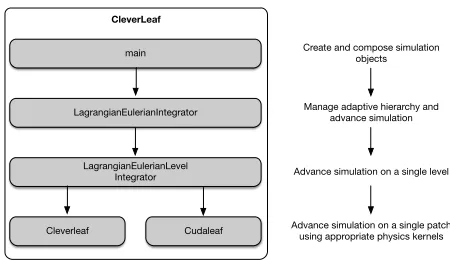
Figure 4: Flexible CPU and GPU implementation of CleverLeaf.
with an interpolated version of the coarse solution. At the end of every timestep, fine solution data is coarsened onto the coarser levels of the hierarchy. We have developed refine operators that linearly interpolate zone-, node- and edge-centred data, and a coarsen operator that “inject” zone-centred data. All these operators run in parallel on a GPU. Operators that conservatively coarsen zone-centred data using volume-weighting and mass-weighting have also been developed as part of the CleverLeaf mini-application, and are described later in the paper.
4
CleverLeaf
The GPU-based SAMRAI extensions described so far have been used to port the CleverLeaf mini-app to GPUs. The original version of CleverLeaf is a CPU-based code, which extends the CloverLeaf mini-app by adding AMR [3]. CloverLeaf is a 2D explicit hydrodynamics mini-app that solves Euler’s equations on a structured grid [8,12,13]. Both CloverLeaf and CleverLeaf are available for download as part of the Mantevo suite [1].
[image:12.612.190.415.228.359.2]un-...
Fine Box
(1,1)
(4,4)
Coarse Box
(1,1) (2,2)
T0
T0 T0 T0
T0
.
coarsei =
Σ4j=1fjvolj
[image:13.612.194.421.135.315.2]voli
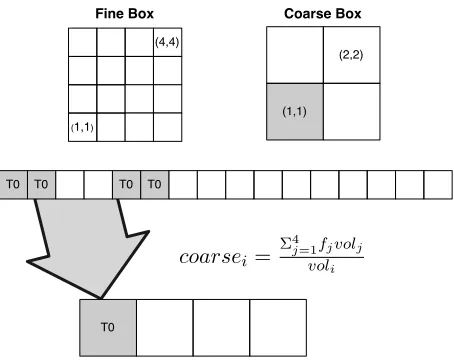
Figure 5: Data-parallel coarsen operators implemented in CUDA.
changed even when a different patch integrator is used. The similarity in the inter-faces between the CPU-based PatchData classes and their GPU-based coun-terparts meant that we were able to easily modify the existing code. To port CleverLeaf to GPUs, we created a new patch integrator, and all references to CPU-based PatchData objects were replaced with GPU-based objects, and the data from these objects was passed to CUDA kernels rather than the existing numer-ical methods written in Fortran. Figure 4 shows how the two patch integrator classes are driven by the top level algorithm. The communications are handled by theLagrangianEulerianLevelIntegratorclass and SAMRAI. The
PatchDatainterface ensures that no additional changes are needed when using data allocated on the GPU.
Additionally, we have written mass-weighted and volume-weighted coarsen operators that run on the GPU; these are are required to conserve mass in the sim-ulation. Each coarsen operator follows the same general pattern, with one CUDA thread being launched for every coarse value that needs to be filled. This thread then reads the relevant fine values and performs the necessary mathematical oper-ations to calculate the coarse value. Figure 5 shows this operation for the volume-weighted coarsen.
.
.
. Analytic.. . Numerical..
... .. 0.0 . 0.5 . 1.0 .
0.5
. 1 . x . ρ ... .. 0.0 . 0.5 . 1.0 . 0 . 0.5
. 1 . x . u ... .. 0.0 . 0.5 . 1.0 .
0.3 .
0.035.4 .. 0.45
.
x
.
[image:14.612.142.473.131.205.2]e
Figure 6: Plot of density, velocity, and energy att = 0.2 for Sod’s shock tube problem.
in parallel. This set of flagged cells is then copied to host memory and passed to SAMRAI to generate the new patch hierarchy. For improved performance, we compress the set of tags on the device from integers to bits, this reduces the amount of data that must be transferred by 321 . We also only copy back the array of tags for patches where some tag is set, avoiding redundant copies of arrays that will not affect the structure of the hierarchy.
5
Accuracy and Performance
In this section we present a detailed study of the accuracy and performance of Clev-erLeaf. Despite the main role of mini-apps being to investigate issues surrounding application performance, we present an accuracy study to reassure the reader that our GPU-based library functions correctly and is ready to be used in a production application.
5.1 Accuracy
To verify the accuracy of the results produced by CleverLeaf, we have used three test problems, comparing numerical results to exact, or converged, solutions. Whilst these test problems are somewhat contrived, the goal of CleverLeaf is not to sim-ulate complex hydrodynamic systems, and instead to provide an accurate indicator into the performance of AMR and hydrodynamics algorithms of interest. Validat-ing the accuracy of CleverLeaf allows us to be confident that the AMR and hy-drodynamics routines are correctly implemented, and that they will represent more complex codes using similar algorithms.
5.1.1 Sod’s Problem
are initially at rest, with the initial conditions being specified as follows:
ρl = 1 ρr= 0.125 (3)
pl = 1 pr= 0.1 (4)
The interface is at the point x = 0.5. At timet > 0 the two regions begin to interact, with a shock wave forming and travelling towards the right-hand boundary of the domain.
Figure 6 shows the density, velocity and energy profiles of the domain at time
t= 0.2. CleverLeaf was run with 3 levels of AMR, a refinement ratio of 2, and a resolution of∆x = 0.001at the finest level. The solution contains a small error at the contact discontinuity and in the rarefaction, however across the rest of the domain the solution is almost exact, and no oscillations are present. These small errors at the discontinuity are expected due to the numerical noise associated with modelling a discontinuity using a second-order method.
5.1.2 Interacting Blastwaves
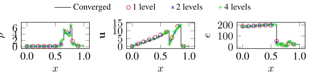
Despite not having an analytic solution, Woodward and Collela’s interacting blast-wave problem [21] can be solved to mesh convergence. We can then compare the error at lower mesh resolutions to understand the behaviour of CleverLeaf as the number of refinement levels is increased.
The interacting blast wave problem consists of a two reflecting walls seperated by distance unity. The densityρ = 1.0throughout the problem, and three regions of ideal gas with different initial pressures are used to create the strong shocks. The left region makes up the leftmost tenth of the volume; the right region, the rightmost tenth. The initial pressures in the left, middle and right regions of the domain are:
pl= 1000 pm = 0.001 pr = 100 (5)
.
.
. Converged.. . 1 level.. . 2 levels.. . 4 levels..
[image:16.612.149.466.130.206.2]... .. 0.0 . 0.5 . 1.0 . 0 . 2 . 4 . 6 . x . ρ ... .. 0.0 . 0.5 . 1.0 . 0 . 5 . 10 . 15 . x . u ... .. 0.0 . 0.5 . 1.0 . 0 . 100 . 200 . x . e
Figure 7: Plot of density, velocity, and energy att = 0.038for the Woodward-Colella interacting blastwaves problem.
IPA Titan
Processor Intel Xeon E5-2670 AMD Opteron 6274
Clock 2.6 GHz 2.2 GHz
Accelerator NVIDIA Tesla K20x NVIDIA Tesla K20x
PCI gen
Nodes 8 18,688
CPUs/node 2×8cores 1×16cores
GPUs/node 2 1
CPU RAM/node 128 Gb 32 Gb
GPU RAM/node 6 Gb 6 Gb
Interconnect Mellanox FDR Infiniband Cray Gemini
Compiler Intel 13.1.163 Intel 13.1.3.192
MPI MVAPICH 1.9 Cray MPT
CUDA Version 5.5 5.5
Table 1: IPA and Titan: hardware and software configurations.
5.2 Performance
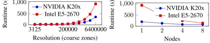
To asses the performance and scalability of our implementation we performed a series of experiments using two different architectures: the IPA testbed machine at Lawrence Livermore National Laboratory and the Titan supercomputer at Oak Ridge National Laboratory. The hardware and software configuration of each plat-forms is detailed in Table 1. The experiments use a range of problem sizes and node counts, and are designed to test both serial performance and parallel scalability.
5.2.1 Serial Performance Analysis
[image:16.612.175.438.256.421.2]... .. 3125 . 200000 . 6400000 . 0 . 500 .
1,000
.
Resolution (coarse zones) . Runtime
(s)
.
. NVIDIA K20x.. . Intel E5-2670..
(a) Serial performance.
... .. 1 . 2 . 4 . 8 . 0 . 500 .
1,000
. Nodes . Runtime (s) .
. NVIDIA K20x.. . Intel E5-2670..
[image:17.612.125.491.136.212.2](b) Strong-scaling parallel performance.
Figure 8: CPU vs. GPU performance comparison on up to 16 GPUS.
small problem sizes the GPU and CPU performance are similar, however, at large problem sizes, we see a performance improvement of over 2.6×. This performance improvement at larger problem sizes is typical of the throughput-oriented GPU architecture.
5.2.2 Parallel Performance Analysis
The second performance experiment investigates the scalability of our code as the number of GPUs is increased from 2 to 16 (1 to 8 nodes), we also include equivalent results for the CPU-based code. The experiment is astrong-scalingstudy, where the problem size remains constant as the number of GPUs (or nodes) is increased. We use the 6.4 million zone problem and run for 1000 timesteps. The results of this experiment are detailed in Figure 8(a), and for all node counts, the performance of the GPU-based code is better than the GPU-based code. For a single node, with two GPUs compared against two CPUs (16 cores), the GPUs are 4.87×faster. At eight nodes (16 GPUs vs. 128 cores) the GPU-based code is still 1.92×faster. We attribute this reduction in performance to the data transfer required during the boundary exchanges and the regridding phase beginning to dominate the simulation runtime; a consequence of running our experiment as a strong-scaling study and the effects of Amdahl’s law. Since the parallel region of the code is so small, runtime is dominated by the serial fraction and as additional GPUs are added, the parallel region represents only a small portion of overall runtime compared to the serial regions of the code [?].
(a)ρand finest level patches att = 0.
[image:18.612.149.465.127.224.2](b)ρand finest level patches att= 2.5.
Figure 9: Triple point shock interaction: initial and final density and patch config-uration.
... ..
1 .
4 .
16 .
64 .
256 .
1024 .
4096 .
10E-10 .
10E-9 .
10E-8 .
10E-7 .
10E-6 .
10E-5 .
Nodes .
Grind
time
(s/cell)
.
. Total.. . Hydrodynamics.. . Synchronisation.. . Regridding..
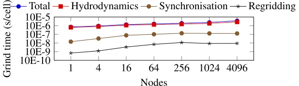
Figure 10: Weak-scaling performance analysis on Titan.
split into three regions, and as the simulation progresses from the initial state shown in Figure 9(a), a strong shock travels from left to right. This shock generates a large amount of vorticity and creates a complex area of interest, creating a large number of patches that are shown as black lines in Figure 9(b).
[image:18.612.150.459.277.366.2]6
Conclusions and Future Work
In this paper we have described our native GPU-based AMR package, and shown how it can be used in a hydrodynamics mini-application. Using the object-oriented design of the SAMRAI library we developed a set of classes that allocate and manipulate patch-based data on the GPU. Our implementation isnative, with data residing in GPU memory at all times, and we provide the routines necessary for transferring data between GPUs on different nodes, and coarsening and refining data in parallel on the GPU. The novelty of this work lies in the fact that our implementation isnative, and that we have developed the first fully data-parallel versions of a range of coarsen and refine operators. We validated the accuracy of our implementation, and compared the performance and scalability of our GPU-based code to the exsting CPU-GPU-based code. The GPU-GPU-based code is up to 4.87× faster than the CPU-based code, and we have demonstrated scalability on up to 4096 GPUs on the Titan system at Oak Ridge National Laboratory. In future work we plan to investigate ways to mitigate the performance impact of copying data between the GPU and host memory by overlapping data transfer and computation. We also plan to investigate mechanisms to allow patches to be “spill over” into CPU memory and then be transferred back to the device when necessary, this will allow larger problems to be solved and increase the relevance of our implementation to production codes.
Acknowledgements
This article has been authored by Lawrence Livermore National Security, LLC under Contract No. DE-AC52-07NA27344 with the U.S. Department of Energy (LLNL-XXXXXXXXXXX). This work is supported by The Royal Society through their Industry Fellowship Scheme (IF090020/AM), and by the UK Atomic Weapons Establishment under grants CDK0660 (The Production of Predictive Models for Future Computing Requirements) and CDK0724 (AWE Technical Outreach Pro-gramme). This research used resources of the Oak Ridge Leadership Facility at the Oak Ridge National Laboratory, which is supported by the Office of Science of the U.S.B Department of Energy under Contract No. DE-AC05-00OR22725.
References
[2] SAMRAI Overview. http://computation.llnl.gov/casc/ SAMRAI/, May 2014.
[3] D. A. Beckingsale, O. F. J. Perks, W. P. Gaudin, J. A. Herdman, and S. A. Jarvis. Using Mini-Applications to Improve AMR Performance on Contem-porary Compute Platforms. 2014. Submitted toJournal of Parallel and
Dis-tributed Computing.
[4] M. J. Berger and P. Colella. Local Adaptive Mesh Refinement for Shock Hydrodynamics.Journal of Computational Physics, 82(1):64–84, May 1989.
[5] M. J. Berger and J. Oliger. Adaptive Mesh Refinement for Hyperbolic Partial Differential Equations. Journal of Computational Physics, 53(3):484–512, Mar. 1984.
[6] C. Burstedde, O. Ghattas, M. Gurnis, T. Isaac, G. Stadler, T. Warburton, and L. C. Wilcox. Extreme-Scale AMR. InProceedings of the 22nd IEEE/ACM
International Conference on Supercomputing, pages 1–12, 2010.
[7] S. Galera, P.-H. Maire, and J. Breil. A two-dimensional unstructured cell-centered multi-material ALE scheme using VOF interface reconstruction.
Journal of Computational Physics, 229(16):5755–5787, Aug. 2010.
[8] J. A. Herdman, W. P. Gaudin, S. McIntosh-Smith, M. Boulton, D. A. Beck-ingsale, A. C. Mallinson, and S. A. Jarvis. Accelerating Hydrocodes with OpenACC, OpeCL and CUDA. InProceedings of the 24th IEEE/ACM
Inter-national Conference on Supercomputing, pages 465–471, Nov. 2012.
[9] J. A. Herdman, W. P. Gaudin, D. Turland, and S. D. Hammond. Benchmark-ing and ModellBenchmark-ing of POWER7, Westmere, BG/P, and GPUs: An Industry Case Study. SIGMETRICS Performance Evaluation Review, 38(4):16–22, Mar. 2011.
[10] R. D. Hornung and S. R. Kohn. Managing application complexity in the SAMRAI object-oriented framework. Concurrency and Computation:
Prac-tice & Experience, 14(5):347–368, 2002.
[12] A. C. Mallinson, D. A. Beckingsale, W. P. Gaudin, J. A. Herdman, and S. A. Jarvis. Towards Portable Performance for Explicit Hydrodynamics Codes.
InProceedings of the 1st International Workshop on OpenCL, pages 1–12,
Atlanta, GA, May 2013.
[13] A. C. Mallinson, D. A. Beckingsale, W. P. Gaudin, J. A. Herdman, J. M. Levesque, and S. A. Jarvis. CloverLeaf: Preparing Hydrodynamics Codes for Exascale. InProceedings of the Cray User Group, Napa, CA, May 2013.
[14] Q. Meng, A. Humphrey, J. Schmidt, and M. Berzins. Investigating Applica-tions Portability with the Uintah DAG-based Runtime System on PetaScale Supercomputers. In Proceedings of the th ACMIEEE International
Confer-ence on Supercomputing, Nov. 2013.
[15] D. Nicholaeff, N. Davis, D. Trujillo, and R. W. Robey. Cell-Based Adaptive Mesh Refinement Implemented with General Purpose Graphics Processing Units. Technical Report LA-UR-11-07127, Los Alamos National Laboratory, Mar. 2012.
[16] M. L. Sætra, A. R. Bordtkorb, and K.-A. Lie. Efficient GPU-Implementation of Adaptive Mesh Refinement for the Shallow-Water Equations. Oct. 2013.
[17] H.-Y. Schive, Y.-C. Tsai, and T. Chiueh. GAMER: A graphic processing unit accelerated adaptive-mesh-refinement code for astrophysics. The
Astrophys-ical Journal Supplement Series, 186(2):457–484, 2010.
[18] G. A. Sod. A Survey of Several Finite Difference Methods for Systems of Nonlinear Hyperbolic Conservation Laws. Journal of Computational
Physics, 27(1):1–31, Apr. 1978.
[19] J. Vlissides, R. Helm, R. Johnson, and E. Gamma.Design Patterns: Elements
of Reusable Object-Oriented Software. Addison-Wesley, 1995.
[20] P. Wang, T. Abel, and R. Kaehler. Adaptive mesh fluid simulations on GPU.
New Astronomy, 15(7):581–589, Oct. 2010.