Analysis of Computer Network Reliability and Criticality:
Technique and Features
Iraj Elyasi-Komari1*, Anatoliy Gorbenko2, Vyacheclav Kharchenko2, Athanasios Mamalis3
1
Technical & Engineering Faculty, Shoushtar Branch, Islamic Azad University, Khuzestan, Iran 2
Aerospace University, Kharkov Aviation Institute, Kharkov, Ukraine 3
National Technical University of Athens, Athens, Greece
E-mail:*[email protected], [email protected], [email protected], [email protected] Received July 26, 2011; revised August 19, 2011; accepted September 1, 2011
Abstract
The paper describes modern technologies of Computer Network Reliability. Software tool is developed to estimate of the CCN critical failure probability (construction of a criticality matrix) by results of the FME(C)A-technique. The internal information factors, such as collisions and congestion of switchboards, routers and servers, influence on a network reliability and safety (besides of hardware and software reliability and external extreme factors). The means and features of Failures Modes and Effects (Critical) Analysis (FME(C)A) for reliability and criticality analysis of corporate computer networks (CCN) are considered. The examples of FME(C)A-Technique for structured cable system (SCS) is given. We also discuss measures that can be used for criticality analysis and possible means of criticality reduction. Finally, we describe a technique and basic principles of dependable development and deployment of computer networks that are based on results of FMECA analysis and procedures of optimization choice of means for fault-tolerance ensuring.
Keywords: FME(C)A (Failure Modes and Effects (Criticality) Analysis),Computer Network Reliability, Criticality, Corporate Computer Networks
1. Introduction
Lots of formalized dependability assessment techniques based on failure criticality analysis (FME(C)A), con- struction of the event and fault tree (FTA), emergency situation analysis (HAZOP) [1,2], etc. has been devel- oped during the last decade. The International Standard [3] describes Failure Mode, Effects and Criticality Analy- sis (FMECA), and gives guidance as to how they may be applied to achieve various objectives by
providing the procedural steps necessary to perform an analysis;
identifying appropriate terms, assumptions, criticality measures, failure modes;
defining basic principles;
providing examples of the necessary worksheets and other tabular forms.
FME(C)A is a methodology to identify and analyze potential failure modes of the various parts of a system and the effects these failures may have on the system. The purpose of FME(C)A-technique is specification of
modes, sources and critical failure effects, including mul- tiple and dependent failures, assessment of methods and different means CCN fault-tolerance and safety ensuring. It includes four main steps.
1) Analysis of a system structure and possible failures of different systems.
2) Analysis of the failures modes and effects. As a re-sult, the FMEA-table should be built.
3) Qualitative analysis of the failures criticality on the base of their probability of occurrence and severity. As a result, the criticality matrix should be built.
4) Identification of the most critical failures as those that lie above the established criticality diagonal.
FME(C)A is used to identify, prioritize, and eliminate potential failures from the system, design or process be- fore they reach the customer FME(C)A is a technique to “resolve potential problems in a system before they occur”. However, this technique has to be adopted for the system features.
Control Systems, Banking System, etc.) is an actual and important problem. The use of FME(C)A-technique [3], allows to identify the critical failures and failure effects for CCNCA and other kinds of CCNs, to detect the safety threats, to determine necessity of the redundancy introduction and other means for enhancement a prob- ability of accident-free failure effects.
The purpose of this paper is an analysis of features of FME(C)A-technique application for corporate com- puter networks that are the core of distributed informa- tion and control systems (I&CS). The safety and fault- tolerance ensuring of CCN for critical application (CA) (NPP I&C Systems, Airspace Control Systems, Banking System, etc.) is an actual and important problem. The use of FME(C)A-technique [3], allows to identify the critical failures and failure effects for CCNCA and other kinds of CCNs, to detect the safety threats, to determine neces- sity of the redundancy introduction and other means for enhancement a probability of accident-free failure ef-fects.
It is confirmed in publications that show method’s ap- propriateness for security assessment using so-called F(I)MEA (Failure (and Intrusion) Modes and Effects Analysis)-technique and failure effects analysis from recovery time view [4,5].
2. Features of FME(
С
)A-Technique
Application for CCN Dependability
Analysis
Application of methods of the analysis of a Mode and consequences of failures FMEA, and also the analysis of a Mode and Effects of critical failures—FME(C)A for quality standard of reliability of complexes of critical application allows to identify refusals and their Effects, to determine necessity of introduction of reservation of elements of system and the measures raising probability of trouble-free operation [6,7].
The tasks of the reliability ensuring of computer net- work based on the open standards and models (for ex- ample, OSI or TCP/IP models) and used for critical ap- plications according to COTS approach [8] are decided at various layers of these models. The distinctive net- work feature is that network failures are stipulated by four basic causes:
defects of the network hardware and software de-
signing and production;
aging of the network physical components;
objective and subjective external extreme factors (EEF) such as seismic loads, electromagnetic distur- bance (ED), human errors, hacking etc.;
internal information factors which consist in periodic increase of network traffic and, as a result, in conges-
tion of switchboards, routers and servers.
The network basic functional elements which may be analyzed by using FME(C)A-technique are SCS, passive and active telecommunication devices, such as hubs, switchboards and routers, servers and workstations etc. working at various layers of the OSI or TCP/IP models and fallible in consequence of four causes mentioned above. However, application of FME(C)A-technique for evaluation of reliability and fault tolerance through traf- fic overloads, unauthorized operations or human errors requires a separate discussion and are not considered in the given paper. Objects of FME(C)A are, as usual, I&CS components—hardware and software components. There is a modification of FME(C)A-method for soft- ware—SFME(C)A [9]. In [10] it is proposed to apply FME(C)A to hierarchical structures and correspond them to hierarchy of FME(C)A-tables.
3. Results of Application
FME(C)A-Technique for CCN Reliability
Analysis
The classification of failure modes, causes, effects and means of safety and fault-tolerance ensuring for the network functional elements is obtained by using the FME(C)A-format. The various means of safety and fault- tolerance ensuring of the network hardware and software are indicated in the last table column. The probability and the severity for each failure mode of specified com- puter network are determined on the basis of statistical information or expert estimations. It allows to construct a criticality grid, and with its help to execute a qualitative analysis of CCN reliability, to determine a set of the most critical failures and means for their recovery.
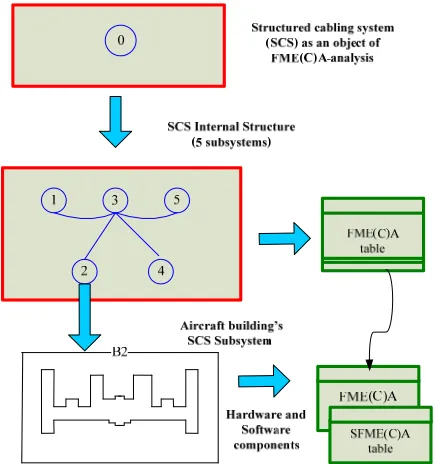
The using of FME(C)A-technique is shown on an ex- ample of analysis of the National Airspace University computer network. Figure 1 shows the university struc- tured cabling system (SCS) [11], also ,for example ana- lysis of the FME(C)A-table for , backbone subsystem for which the FME(C)A-table was obtained (Table 1) and the criticality matrix was constructed (Table 2).
Figure 2 shows an hierarchical approach to the FME(C)A analysis of the computer network of the Na- tional Airspace University “Kh.A.I.”.
4. Failures Criticality Analysis
The second step of FME(C)A technique is a criticality analysis of all failure modes. It performs with the pur- pose to explain the most serious failures and determine ways in which criticality of this failures can be reduced (Figure 3).
cd bd-3
bd-2
bd-4
bd-5 B1
B3
B2
B5
B4
B1-Rectorial building B2-Aircraft building B3-Engine building B4-Laboratory building B5-Radio engineering building B6-Impulse building cd
bd -Campus Distributor
-Building Distributor -Campus Backbone Cable cbc-1
cbc-2
cbc-4
cbc-3
cbc-5
cbc National Aerospace
[image:3.595.89.508.81.270.2]University bd-1
[image:3.595.59.542.316.476.2]Figure 1. University SCS backbone subsystem.
Table 1. Fragment of common FME(C)A—table of university SCS backbone subsystem.
SCS
element Failure Mode Failure Cause Failure Effect
Failure Recovery Means
Means of fault-tolerance provision
Probability of failure
Criticality level
Patch panel connector damage
External extreme factors (EEF); aging; defect
Communication
disturbance replacement Connector redundancy Connector High Low
Patch panel
destruction EEF «» «»
Patch-panel
redundancy Lowest Mean
cd,
bc-1.
.b
c-5
Distributor
destruction «» «»
Repair and recovery
Distributor
redundancy Lowest High
Cable failure (damage)
EEF; aging;
internal defect «»
Cable replacement
Cable redundancy;
link path redundancy Low High
cbc-1.. cbc-5 Message distortion
electromagnetic disturbance (ED)
Short-term communication disturbance;
loss of information -
Electric cable screening; maximum utilization
of optical fiber Low Low
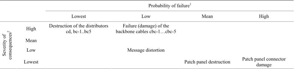
Table 2. Fragment of criticality matrix of university SCS backbone subsystem.
Probability of failure1
Lowest Low Mean High
High Destruction of the distributors cd, bc-1..bc5 backbone cables cbc-1…cbc-5Failure (damage) of the
Mean
Low Message distortion
Sever
ity of
consequences
2
Lowest Patch panel destruction Patch panel connector damage
1The probability of failure is determined by the network service conditions; 2The weight of failure consequences is determined by destination and functions of
system elements, “weight” of failure effects and its influence on a system as a whole.
such analysis: 1) weight of failure consequences, and 2) probability of failure occurrence. The failure criticality defines by “weight” of failure effects on all system and depends on function of faulty element. For computer net- work it can be degree of connectivity decrease. The pro- bability of failure occurrence is determined by the net-
work service conditions. It can be reduced by using structured redundancy.
[image:3.595.61.539.504.616.2]Figure 2. Mapping of assessed system hierarchy to hierar- chy of FME(C)A—tables.
Probability of failure occurence
High
Mean
Low Lowest
Lowest High
Mean
Low
Wei
ght o
f
con
sequences Failure
Criticality diagonal for systems with higher reliability requirements
Area of critical failures
[image:4.595.313.534.78.213.2]Criticality diagonal
Figure 3. Criticality matrix.
there are six different criticality diagonals in total that can be set in the criticality matrix that is shown on Fig-ure 3. The higher is the criticality diagonal the more critical is the system.
In this paper we also propose to use an additional third measure to assess failure criticality, which describes du- ration of system nonoperability [12]. It is very important for the computer and telecommunication systems where the small amount of incorrect connections (due to incur- rect routing) is allowed whereas the high availability of the network is required.
[image:4.595.59.285.349.500.2]This measure depends on recovery time that can be reduced by using automated (computer-aided) recovery means instead of manual operations or automatic (un- manned) means instead of automated ones (Figure 4). For the computer networks these means include dynamic
Figure 4. Failure criticality coordinate system.
routing which is more preferable than static one, the spanning tree protocol against the manual recovery, etc.
5. Means of Failure Criticality Reduction
There are a lot of techniques that can be used for the failure criticality reduction, like:
Patch View System that control integrity of cabling channels and patch-panels at the level of structured cable system;
Adapter Fault Tolerance (AFT) technology that pro- vide hot sparing of network adapters;
Adaptive Load Balancing (ALB), that allocate net- work traffic between four server’s network adapters and four switch ports as well as AFT;
Fast Ether Channel (FEC) technology supporting
flexible channel capacity as well as AFT;
Protocol of dynamic network reconfiguration Span- ning Tree Protocol (STP);
Protocols of dynamic rooting like OSPF and
Cis-coEIGRP that support load balancing.
Most of means mentioned above use redundancy of the cabling channels, ports and network equipment. Some technologies also provide possibility to increase network throughput by using existing redundant roots (like trunk technology) and allow automatic network reconfiguration to isolate failures.
Thus, incorporating of different fault-tolerant mecha- nisms together will provide possibility of complex and ef- ficient failure criticality reduction. However, all existing means have to be ranked taking into account their cost and effectiveness as well as compatibility with another ones.
6. Dependable Development and Deployment
of Computer Networks
6.1. Using FMEA-Technique for Dependable Network Development
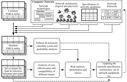
the common FMEA-table and criticality matrix describe- ing failures modes and effects have to be detailed taking into account actual logical and physical architecture of particular computer network as well as the set of network hardware, communication protocols and application soft- ware used (Figure 5).
Two different development strategies are possible. For critical and business-critical applications it is necessary, as a rule, to provide the required level of dependability at the minimum cost, whereas for commercial applications it is important to provide the maximum dependability at the limited cost.
These goals can be achieved by solving optimization problem, taking into account failures criticality, prob- ability of occurrence and cost of fault-tolerance means, their effectiveness and failures coverage. As a result the particular computer network must be updated by using chosen fault-tolerance means.
The principles proposed are in line with recent re- search [13] where a functional failure mode, effects and criticality analysis approach is proposed to address the dependability optimization of large and complex systems.
6.2. The Principles of Dependable and Secure Deployment of Computer Networks
Dependability and security of a computing system is its ability to timely deliver service that can justifiability by
trusted [14]. The typical network faults are physical faults of network equipment and communication media (i.e. cabling system), configuration errors (e.g. errors in
static routing or firewall filtering rules or and security policies), design faults, as a rule, of software components, and interaction faults of physical (electromagnetic inter- ference) or information nature (traffic congestions).
Fault and intrusion tolerance of computer networks, their security and dependability as a whole could be im- proved using the following principles.
1) Defense in depth and diversity (D & D). Defense in depth implicates joint usage of existing intrusion and fault-tolerance mechanisms at the different levels of the network architecture (cabling systems, network equip- ment, network technologies) and layers of the communi- cation model (OSI or TCP/IP) to provide complex deci- sion for dependability ensuring.
2) Adaptability and update (A & U). The essence of this principle is in the dynamic changing of the network architecture and diversity modes according to the ob-served failures and intrusions. The intellectual monitor- ing means for detection of failures and intrusions, their analysis and the choice of better network configurations could be used to achieve that.
7. Conclusions
CCN reliability and safety estimation is the complex task,
100/1000 Ethernet
Network architecture
(logical and physical) network equipmentSpecification of ProtocolsNetwork
Failures & intrusions criticality (cost) and probability analysis
Analysis of cost, effectiveness and compatibility of different means
Risk analysis, optimization and
choice
Updating the network specification,
architecture, set of network equipment,
etc.
Computer Network
Network technologies Common
FMEA-tables
Detailed FMEA-tables
Set of means for fault & intrusion tolerance provision
TCP SONET
FDDI
100VG-AnyLAN
xDSL IP OSPF
HTTP SNMP
UDP
[image:5.595.82.512.429.706.2]ICMP
which cannot be decided in isolation from application area. It is stipulated that the internal information factors, such as collisions and congestion of switchboards, routers and servers, influence on a network reliability and safety (besides of hardware and software reliability and external extreme factors).
Computer networks are the complex systems which contain a lot of elements. Therefore network failures are unavoidable. In this case the risk and criticality analysis [15], survivability and safety assessment [16] are more actual tasks than evaluation of the probability of no- failure operation.
As computer networks have a multilevel hierarchy the network element failures, generally, have a dependent character, i.e. the failure effects at one layer of the OSI
or TCP/IP models are the sources of new failures at suc- ceeding layers. This feature of computer networks can be taken into account by using layered analysis and repre- sentation its results as a hierarchy of FME(C)A-tables. A characteristic feature of active telecommunication de- vices is that they contain not only hardware, but also software components. For the software reliability and safety qualitative analysis the Software ME(C)A-tech- nique may be used [17].
The software tool is developed to estimate of the CCN critical failure probability (construction of a criticality matrix) by results of the FME(C)A-technique. This tool consists of:
database containing common FME(C)A-tables for the network elements with an priori information;
conversational procedure of FME(C)A-analysis and
evaluation of the specified network;
procedure of automatic generation of criticality grids and definition of the most critical network failures; procedure of an automatic choice of critical failure
recovery and fault-tolerance means.
This tool also may be extended by procedures for network simulation and probabilistic assessment of re- liability, safety and survivability. Directions of our future researches are connected with analysis of multiply failures during network development and maintenance and cost-effective means of reducing failures criticality.
8. References
[1] B. B. Begun, O. B. Gorbanov, I. N. Kdenko, Ye. M. Pysmennyy, A. Yu. Zenyu and L. L. Lityinsky, “Probabi- litistic the Analysis of Safety of Nuclear Stations,” in Russian, Kiev National University, Kiev, 2000, p. 568. [2] V.Kharchenko, V. Sklyar, B. Konorev,Yu. G. Аleksev,
G. N. Chertkov, S. А. Zasukha and L. L. Semenov, “As-sessment and Ensuring of Software Quality for Space Systems,” (In Russian), Kharkiv Aviation Institute, Na-tional Aerospace University Named after N. Y. Zhu- kovsky, Ukraine, Kharkov, 2007, p. 244.
[3] IEC 60812 Standard, “Analysis Techniques for System Reliability—Procedure for Failure Modes and Effects Analysis,” FMEA, Geneve, 2006.
[4] A. V. Gorbenko, V. S. Kharchenko, O. M. Tarasyuk and A. A. Furmanov. “F(I)MEA-Technique of Web-Services Analysis and Dependability Ensuring,” Rigorous Devel-opment of Complex Fault-Tolerant Systems, Lecture Notes in Computer Science, Vol. 4175, 2006, pp. 153-167. doi:10.1007/11916246_8
[5] E. Babeshko, V. S. Kharchenko and A. Gorbenko, “Ap-plying F(I)MEA-Technique for SCADA-Based Industrial Control Systems Dependability Assessment and Ensur-ing,” Proceedings of the 2008 Third International Con-ference on Dependability of Computer Systems Dep-CoS-RELCOMEX, Szklarska Poreba, 26-28 June 2008, pp. 309-315.
[6] H. Newi, J. Kiefer, J. Wolberg and H. Mihm, “Availabil- ity and Train Delayas—The CADM Approach,” Pro-ceeding of Safety and Reliability Conference, Rotterdam, 1999, pp. 159-163.
[7] ANSI/IEEE 352, “IEEE Guide for General Principles of Reliability Analysis of Nuclear Power Generating Station Safety Systems,” IEEE, New York, 1987.
[8] J. M. Voas, “The Challenges of Using COTS Software in Component-Based Development,” Computer, Vol. 31, No. 6, 1998, pp. 44-45. doi:10.1109/MC.1998.683006 [9] S. Hasan, B. Tekinerdogan and M. Aksit. “Reliability
Analysis at the Software Architecture Design Level using Enhanced Failure Modes and Effects Analysis Ap-proach,” Springer, Berlin, 2007, pp. 132-157.
[10] I. E. Komari. “Network Availability Assessment by Use of FME(C) A-Technique and Markov’S Models,” Pro-ceedings of IEEE International Conference of East-West Design & Test, Yerevan, 2007, pp. 697-701.
[11] ISO/IEC 11801, “Generic Cabling for Customer Prem-ises,” ISO/IEC JTC 1/SC 25, Interconnection of Informa-tion Technology Equipment, 1995.
[12] A. Zolfaghari and F. Kaudel, “Measuring Outages in Telecommunications Switched Networks,” IEEE Journal on Selected Areas in Communications, Vol. 31, No. 6, 1994, pp. 46-51. doi:10.1109/49.265703
[13] D. Verneza and F. Vuillea, “Method to Assess and Opti-mise Dependability of Complex Macro-Systems: Appli-cation to a Railway Signalling System,” Safety Science, Vol. 47, No. 3, 2009, pp. 382-394.
doi:10.1016/j.ssci.2008.05.007
[14] A. Avizienis, J. C. Laprie, B. Randell and C. Landwehr, “Basic Concepts and Taxonomy of Dependable and Se-cure Computing,” IEEE Transactions on Dependable and Secure Computing, Vol. 1, No 1, 2004, pp. 11-33. doi:10.1109/TDSC.2004.2
[15] V. S. Kharchenko and D. A. Cherepakhin, “Risk Analysis of Control Systems by Use of QD-Diagrams and FMECA- Approach,” Proceeding of ESREL2001 Conference, Torino, 16-20 September 2001.
Multistage Degradation by Use of QD-diagrams,” 5th In-ternational Conference on Probabilistic Safety Assess-ment and ManageAssess-ment, Osaka, 2000, pp. 525-531. [17] J. Bowles and W. Chi, “Software Failure Modes and