© 2019, IRJET | Impact Factor value: 7.211 | ISO 9001:2008 Certified Journal
| Page 355
An Efficient Wallace Tree Multiplier Using Modified Adder
Ritu
1, Medha Tiwari
2, Mr. Rachit Patel
3, Dr. Sapna Katiyar
41
Ritu (B. Tech (ECE), ABES INSTITUTE OF TECHNOLOGY)
2
Medha Tiwari (B. Tech (ECE), ABES INSTITUTE OF TECHNOLOGY)
3
Mr. Rachit Patel (Assistant professor-ECE, ABES Institute of Technology), U.P., India
4Dr. Sapna Katiyar (Head of Department-ECE, ABES Institute of Technology), U.P., India
---***---Abstract -
Multipliers are major blocks in the most of thedigital and high-performance systems such as
Microprocessors, Signal processing Circuits, FIR filters etc. In the present scenario, Fast multipliers with less power consumption are leading with their performance. Wallace tree multiplier with carry select adder (CSLA) using binary excess-1 counter (BEC) is one of the fastest multipliers but utilizes more area. To improve the performance of this multiplier, CSLA is replaced by modified adder consisting of carry skip adder and carry save adder which not only reduces the area at gate level but also reduces delay. Area and delay calculations for the Wallace tree multiplier using modified adder are giving good results as compared to regular Wallace tree multiplier.
Key Words
:
Carry Select Adder (CSLA), Binary to Excess one converter (BEC), Ripple Carry Adder (RCA), Carry skip adder (CSkA), Carry save adder (CSA).1. INTRODUCTION
The performance of a processor mainly depends on the multiplier as most of the processors time depends on the multiplication process. Major applications like VLSI, digital signal processing, deep learning, artificial intelligence requires high performing processors to obtain the processing of huge amount of data. Techniques involved in most of the multipliers are computation of partial products and then the summation of partial products. In parallel multipliers number of partial products to be added is the main parameter that determines the performance of the multiplier. Multiplier circuit design is based on add and shift algorithm. Partial products are generated by the multiplication of the multiplicand with one multiplier bit. The partial products are shifted according to their bit orders and then added. The addition can be performed with normal carry propagate adder. N-1 adders are required where N is the multiplier length. Multiplier architecture consists of three stages, partial products generation stage these are generated by AND operation, partial products addition stage carried by different adders and final addition stage. Speed of the multiplier depends upon partial products addition stage.
Wallace tree multiplier is designed with CSLA in order to increase the speed[2]. This gives the solution for the problem of carry propagation delay by independently generating multiple carries and then selects a carry to obtain
the sum. As we know CSLA is not area efficient as it uses multiple pairs of RCAs to produce partial sum and carry by considering cin=0 and cin=1, then final sum and carry are selected by multiplexers, this disadvantage made a reason to replace RCA in regular CSLA with BEC. BEC is replaced instead of RCA with cin=1 in regular CSLA to achieve the lower area[1], less power consumption and a smaller number of logic gates, then final sum and carry is selected through multiplexer. The importance of BEC logic stems from the large silicon area reduction when the CSLA with large number of bits are designed. In CSLA with BEC uses four multiplexers. To reduce the area consumption on gate level the CSLA can be replaced with carry skip adder.
2. Carry Select Adder
CSLA[1] is the combination of multiple RCAs, the idea behind CSLA is to avoid the propagation of carry from one bit to another by using two adders in parallel both with input carry as 0 and 1. As shown in fig.1, there are two 4-bit ripple-carry adders composed of four full adders and multiplexers. One ripple-carry adder uses a carry-in value of 0 while the other uses a carry-in value of 1. Each ripple-carry adder generates sum and carry-out values and the actual carry-in value is used as select line to choose between the outputs generated by each ripple-carry adder by using multiplexers. This reduces the problem of carry propagation delay in ripple-carry adders and is more efficient than ripple-ripple-carry adders at adding larger (higher bit-width) values of A and B. Using two adders for each bit makes it area inefficient and hence the solution to this problem is the use of BEC-1 instead of RCA for input carry as 1.
© 2019, IRJET | Impact Factor value: 7.211 | ISO 9001:2008 Certified Journal
| Page 356
3. CSLA USING BINARY TO EXCESS-1
BEC[2] code converter is used in CSLA when the carry input is one. BEC increments the input bits by one so it is chosen in the case where carry input is given as 1 in CSLA. BEC uses a smaller number of logic gates than N-bit full adder structure in order to optimize area and power. N-bit RCA is replaced by (N+1) bit BEC. Therefore, Modified CSLA[2] has low power and less area than conventional CSLA. Memory is also minimized by using BEC structure in place of full adders as BEC structure consist of NOT, AND, XOR gates.
Fig-2:
Binary to excess-1 converter
Fig-3: CSLA using BEC-1
4. CARRY SKIP ADDER
As the name indicates, Carry Skip Adder (CSkA)[3] uses skip logic in the propagation of carry. The CSkA consist of simple RCA with a speed up carry chain. MUX will decide the output carry. Carry skip adder is a fast adder compared to ripple carry adder when addition of large number of bits. Carry skip adder has delay in the order of O(n). The carry skip adder has a skip logic block that makes it faster. Propagate condition: Pi = Ai XOR Bi[3]
Fig-4: Carry skip logic
Fig-5: Carry skip logic using OR gate
5. CARRY SAVE ADDER
A CSA[3] is just a set of one-bit full adders, without any carry-chaining. Therefore, an n-bit CSA receives three n-bit operands. Carry save adder is similar to RCA. Both the adders can perform addition of three numbers at a time namely A, B, C and output as sum and carry. In RCA two numbers and one input carry are added on the other hand in CSA three numbers can be added at once. Entire sum can be calculated only after the carry is shifted by the left side.
A + B + C = sum + carry
© 2019, IRJET | Impact Factor value: 7.211 | ISO 9001:2008 Certified Journal
| Page 357
6. WALLACE TREE MULTIPLIER
Wallace tree multiplier[4] consists of three steps.
1. For a 4-bit multiplication firstly, the partial products are obtained by AND operation.
2. Group the first three rows of partial products and add them together by using carry save adder (CSA). The carry generated by the adders in each column is rippled to preceding column as shown in fig.6 3. The outputs of these adders in the first stage are
added with the remaining rows of partial products by using full and half adders.
To minimise delay and power consumption it can be implemented by using other efficient adders.
6.1 USING CSLA
In this algorithm also partial products are generated and CSA is used to obtain sum and carry which will be added with the last row of the partial products using CSLA.
Fig-7: Block diagram of Walace tree multiplier using CSLA
6.2 USING CSLA WITH BEC-1
In this multiplier the final sum is obtained by replacing the RCA of CSLA with BEC-1[1] and hence making it area efficient.
Fig-8: Block diagram of Wallace tree multiplier using BEC
6.3 USING CSkA
The CSLA with BEC-1 is area inefficient because along with adders (Full Adders and Half Adders) it is using four multiplexers. These multiplexers can be removed by using CSkA instead of CSLA. Fig.11 shows the block diagram of Wallace tree multiplier using CSA and CSkA. Here the partial products are as follows
p0(0), p0(1), p0(2), p0(3) for ai AND b0
p1(0), p1(1), p1(2), p1(3) for ai AND b1
p2(0), p2(1), p2(2), p2(3) for ai AND b2
p3(0), p3(1), p3(2), p3(3) for ai AND b3
P0(0) is directly obtained at the output. Now in first and second stages the products are summed up using carry save adder. From first stage the sum obtained are s11, s12, s13, s14 and their respective carries i.e. c11, c12, c13, c14. From second stage the sum obtained are s22, s23, s24, s25 and their respective carries are c22, c23, c24, c25. The final result is obtained by using carry skip adder in third stage. The final product contains cout, s36, s35, s34, s33, s22, s11, p0(0).
© 2019, IRJET | Impact Factor value: 7.211 | ISO 9001:2008 Certified Journal
| Page 358
Fig-10: Block diagram of 4-bit Wallace multiplier usingCSkA
7. RESULT
Wallace Multiplier is synthesized using XILINX ISE Design Suite 14.2 and is implemented on Field Programable Gate Array (FPGA) device xc6slx9-3tqg144 of Spartan 6 family.
The Input output waveforms which are generated by using XILINX software and device utilization summary are shown.
Fig-11: Simulation of 4-bit traditional Wallace tree multiplier
Fig-12: simulation of 4-bit Wallace multiplier using CSLA with BEC-1
Fig-13: Simulation of 4-bit Wallace multiplier using CSkA
8. CONCLUSION
© 2019, IRJET | Impact Factor value: 7.211 | ISO 9001:2008 Certified Journal
| Page 359
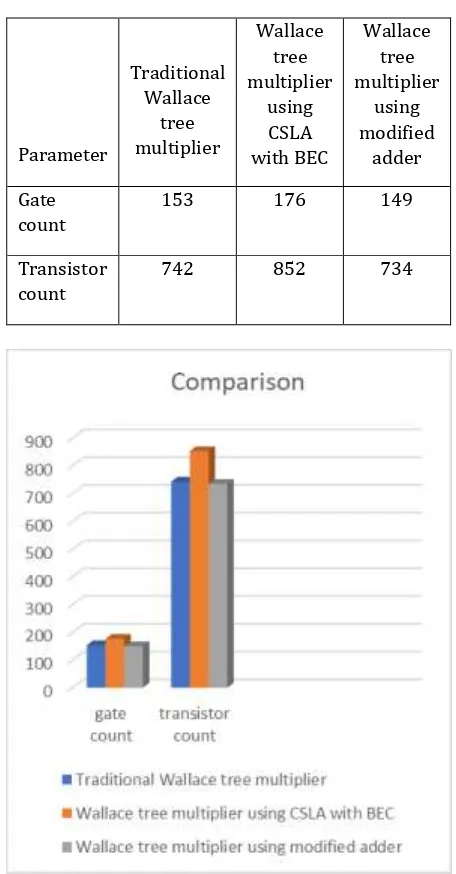
Table -1: Comparison tableParameter
Traditional Wallace
tree multiplier
Wallace tree multiplier
using CSLA with BEC
Wallace tree multiplier
using modified
adder
Gate count
153 176 149
Transistor count
742 852 734
Chart -1: Comparison chart
REFERENCES
[1] https://ieeexplore.ieee.org/document/7746174
[2] G.Challa Ram, D.Sudha Rani, R.Balasaikesava, K.Bala Sindhuri,’’ Design of Delay Efficient Modified 16 bit Wallace Multiplier’’, IEEE International Conference On Recent Trends In Electronics Information Communication Technology, May 20-21, 2016, India [3] Sujan Sarkar1, Jishan Mehedi2, “Design of Hybrid
(CSA-CSkA) Adder for Improvement of Propagation Delay,” 2017 third international conference on research in computational intelligence and communication networks
[4] ShahzadAsifandYinanKong,“Low-Area Wallace Multiplier,” Hindawi Publishing Corporation VLSI Design Volume 2014, Article ID 343960.