© 2019, IRJET | Impact Factor value: 7.211 | ISO 9001:2008 Certified Journal | Page 3964
Accomplishment Interpretation and Reformative Study for RCC
Structure under Blast Loading
Keshav Kumar Mishra
1, Suhail Ahmed Qureshi
21
M. Tech Student, Dept. of Civil Engineering, Prashanti Institute of Technology and Science, Ujjain (M.P.), India
2
Professor, Dept. of Civil Engineering, Prashanti Institute of Technology and Science, Ujjain (M.P.), India
---***---Abstract - In this study, dynamic analysis is performed
using ANSYS Workbench (Version 14.0) in order to determine the effects of blast consecquence on the modeled structure, parameters considered in terms of energy in the analysis is compare with the manual calculation. Further, temporal behaviour of different parameters such as strain, stress, deformation and pressure on the structure as well as parameters of explosive such as total energy, kinetic energy, internal energy and density of the explosive, results are studied. Analysis is carried out in two parts, in first part, the behaviour of a two by four bay three story rectangular shape frame when subjected to a large amount of explosive is studied. The distance between structure and explosive was varied from 10 m up to 25 m in longer as well as in shorter side of the structure. In the second part a G+7 story Structural building is analysed III this Structural building was subject to a explosion of half ton of TNT at a distance of 10m away from the structure. From the analysis it was found that deformation increases in case of shear wall by 18% and stress reduce with 13.5% while in case of heavy section deformation reduces with 25% and stress reduces to 39%. Apart from these remedies, if any local failure occurs due to increased stresses, the destruction of the whole structure can be prevented with the use of alternate supporting members like steel bracing which leads to about 1.6% increase in the total cost of the structure. The use of heavier sections leads to an increment of about 0.8% in the costing and the same comes to be 0.9% when shear wall is considered. It was observed that it is very difficult to design and costly to construct a structure for the forces acting at the time of blast. While another way to secure the structure from the blast is to mitigate the energy of explosive by proper arrangements of interior & exterior architecture as well as aesthetics & functionality of the Structural building
Key Words:TNT, Ansys, Blasting, Dynamic Analysis, Energy,
1. INTRODUCTION
In recent years due to different accidental or intentional, blasts all over the world, resulted in number of initiatives to study the resistance of structures to blast and to develop systems to reduce the hazard of such attacks. The main aim of these is to protect & provide safety to those who are in/around the Structural building, and can be killed or injured by the destruction of the structure and the falling debris. One of the main areas of research and enlargement in this field is the progressive destruction prevention. From
structural engineering and construction point of view structure must be designed so that it can withstand a terrorist bomb attack with minimum or no damage. Designing such a highly protected Structural building requires a significant amount of funding as well as resources. In addition, to achieve the objective of the minimum damage, the designers may sacrifice the exterior and in some cases the internal aesthetics & functionality of the Structural building. Although in case of military, the high cost of a Structural building (like bunkers) can be justified but for civilian Structural buildings, such high costs cannot be afforded and the loss of aesthetics & functionality may not always be acceptable. This was because of the assumption that civilian Structural buildings had a very low prospect to be a target of terrorist attack. But it is not so after events like April 19, 1995 Murrah Federal Office Structural building, Oklahoma City bombing, September 11, 2001 World Trade Centre, Pentagon, attacks. These recent events show the importance of study & design of blast resistant structures to withstand the main and secondary effects due to blast. In recent times of heightened terrorist activities and alarming threats of future attacks, it has become of the utmost importance to develop blast resistant structures. In case of accidental or intentional blast problem is referred as a BLAST-CONSECQUENCE problem, this problem may be divided in two parts: the first part involves assessing the damage that a structure will suffer when it is hit by a blast wave of a specific strength, the second part deals with the design and testing of structures that are capable to withstand or mitigate the strength of the blast wave. One of the biggest challenges in this area is the lack of erudition of the amount and the location of the explosive, especially in the case of a terrorist attack.
1.1
METHODOLOGY & MODELLING APPROACH
Methodology
In the current project blast analysis is performed on G+ 3 structures for blast of an explosive material at different distance from one of the face of the structure for same amount of explosive material. For this analysis the methodology is as follows:
An extensive survey of the literature on the blast analysis and there effects on the structure is performed. Based on the numerical and parametric study, a step by
© 2019, IRJET | Impact Factor value: 7.211 | ISO 9001:2008 Certified Journal | Page 3965
Dynamic analysis in ANSYS14.0 for evaluating energy ofthe explosive and its comparison with energy has been calculated manually.
For determine the behaviour of explosive & effects of blast on structure, a problem of a G+ 3 structures having 2×4 bay is taken & analyzed for different stand-off distances with a large amount of explosive.
After that a G+ 7 unsymmetrical structure is taken and analyzed for stand-off distances of 10 m with half ton of TNT explosive & determine the failure of vertical supporting member
Effects of explosive on the structure and there safety measures are determined.
Modelling Approach
The modelling approach includes preparing the model using a parametric tool having an integrated 3D CAD/CAM solver. The tool used for modelling is Creo Elements/Pro, Pro/ENGINEER which consist mainly parametric feature-based modeled and solid modelling. Figure 1 shows the geometry in solid modelling, fully described in 3-D space in which the objects can be viewed from any angle
Fig -1: Geometry in Solid Modelling Description of the Structure Modelled
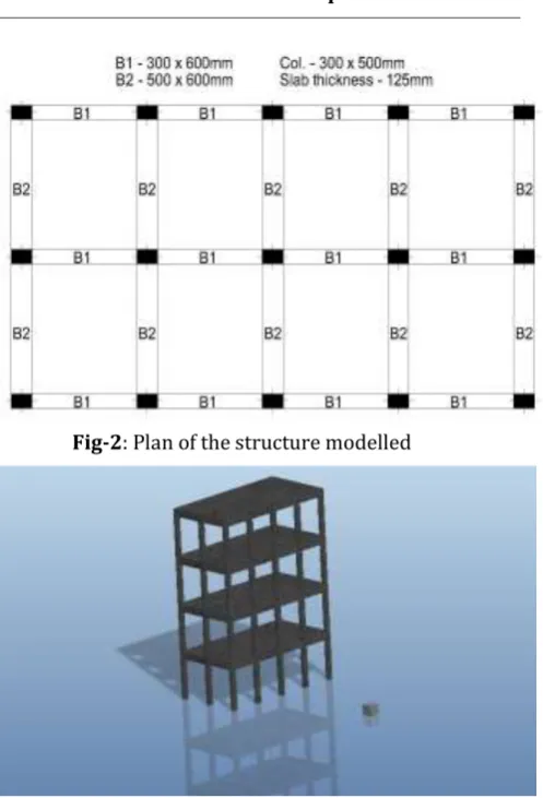
For the determination of explosive effects on the structure a 3 story Tension member column frame with no infill is used. The story height and bay width is 3m. Frame is of 2×4 bay (6m×12m) and in the frame column of size of 300×500 mm, Tension member of size 300×600 mm (B1) and 500×600 mm (B2) and slab of thickness 125mm have been used (Fig-2).
Fig-2: Plan of the structure modelled
Fig-3: Structure modelled in Pro-E
After that a seven story Structural building is used and modelled for the analysis. The story height is 3m, frame is unsymmetrical and column position is shown in Figure 3. Structure is first analysed and design using STAAD.pro for earthquake forces, after that model with same section dimension is modelled and analysed for blast of half ton of TNT with stand of distance 15 m. Size of column used are 700X700mm, 300X700mm and 200X700 mm and there orientation are shown as in Figure 4.
[image:2.595.323.572.75.441.2] [image:2.595.100.239.378.524.2] [image:2.595.329.568.570.742.2]© 2019, IRJET | Impact Factor value: 7.211 | ISO 9001:2008 Certified Journal | Page 3966
Fig-5: Structure modelled in Pro-E1.2 Dynamic Analysis Detail
I. An analysis system has been selected on ANSYS workbench.
II. Then material property is selected from the ANSYS material library for assigning to the model.
Following material is used in the analysis, materials with their property are: -
a. Concrete
b. TNT
III. Structure modelled in Pro-E has been imported in the analysis system created in the ANSYS workbench platform.
IV. Coordinate system, Connections & mesh has to be defined. As model is prepared in different parts and then assembled, behaviour of contacting surface is to be defined. Contact region may be of different type Bonded, No separation, Frictionless, Rough, and Frictional.
V. Mesh has been generated from explicit type with coarse, medium or fine type with defining initial conditions (such as support condition, load definition etc.) in setup.
VI. Solution information has been defined and analysis is performed to get analysis results in the form of energy, stress, strain, deformation etc.
Table-1: Material Properties
2. ANALYSIS RESULT
Results of analysis are shows in chart 1 to 3; chart-1 gives the total deformation of the structure at different time after explosion takes place. Clash wave produce due to explosion take one and a half millisecond to travel distance and strikes the structure. Maximum deformation cause due to explosion is 6.73 mm.
Chart -1: Time v/s Total deformation of Structure
© 2019, IRJET | Impact Factor value: 7.211 | ISO 9001:2008 Certified Journal | Page 3967
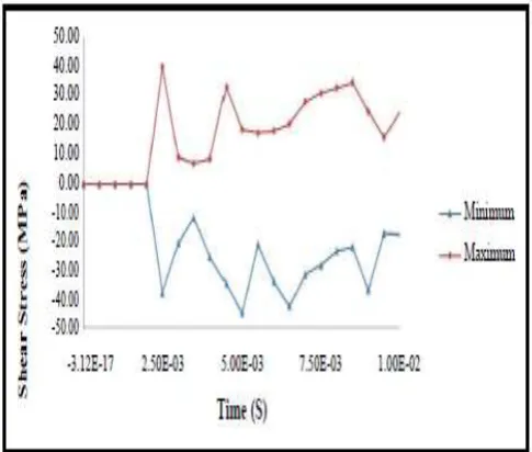
Chart-2 shows shear stresses generated in the structure dueto explosion. Maximum magnitude cause due to explosion is 64.085 MPa. This stress is much higher than the yield stress. Thus local failure caused shear stress due to dynamic loading is assumed to be higher than the yield stress
.
3. Remediation Measures
Due to localized failure of main supporting column the entire upper floor gets unsupported and destruction of structure occurs. For preventing destruction, following modifications may be done to the structure:
1. Heavy section
2. Shear wall
3. Steel bracing
The provided cross sectional area (300X700mm) of the columns was found to be insufficient to bear the stresses caused due to blast. This can be rectified by increasing the sectional dimensions (700X700mm) so as to bear the blast loads. The result from the above analysis gives the position as well as number of element in which stresses exceed the safe limits. The position, orientations and section dimension of those members is thus modified to with stand the blast loads. Using of shear wall is another solution for reducing the stress develops due to explosion. For resisting shear force shear wall is used in different orientation randomly and analyzed. Figure 6 and 7 shows the model prepares for analysis.
Fig-6: Modal with heavy section Fig-7 Modal with shear wall
Maximum magnitude reduces by 25% at the lift core because energy of the clash wave passes through the member and is absorbed. In case the section dimension 300x700 mm is considered, deformation in the member number c-2, c-3, c-4 and c-5 is 1.51, 1.27, 0.98 and 1.04 mm while the section dimensions of 700x700 mm is used, the deformation reduces to 0.88, 0.70, 0.69 and 0.72 mm
Chart -3: Time v/s Total deformation of Structure with heavy section
Similarly chart-4 and 6 shows the shear stress on the structure due to blast loading. Maximum magnitude reduces by 39%. When section dimension is 300x700 mm shear stress crosses the safety limit and causes local failure. Members in which maximum failure occur due to stress are c-2, c-3, c-4, c-5 and stress are 22.83, 21.18, 23.08 and 21.05 MPa while section dimension of 700x700 mm is used stress gets reduced to 4.58, 4.23, 3.40 and 3.10 MPa
.
Chart -4: Time v/ Shear Stress of Structure with heavy section
[image:4.595.313.556.438.644.2]© 2019, IRJET | Impact Factor value: 7.211 | ISO 9001:2008 Certified Journal | Page 3968
IrChart -5: Time v/s Total deformation of Structure with shear wall
et Chart -6: Time v/ Shear Stress of Structure with shear wall In the above analysis it is found that deformation is increases in case of shear wall by 18% and stress reduce with 13.5% while in case of heavy section deformation reduces with 25% and stress reduces to 39%. Apart from these remedies, if any local failure occurs due to increased stresses, the destruction of the whole structure can be prevented with the use of alternate supporting members like steel bracing which leads to about 1.6% increase in the total cost of the structure. The use of heavier sections leads to an increment of about 0.8% in the costing and the same comes to be 0.9% when shear wall is considered. chart-7 and 8 shows the temporal variation of absolute value of deformation and shear stress in the section.
Chart -7: Temporal variation of absolute deformation in the structure
Table-2: Absolute deformation in structure
© 2019, IRJET | Impact Factor value: 7.211 | ISO 9001:2008 Certified Journal | Page 3969
Table-3: Absolute Shear stress in the structure4. CONCLUSIONS
The blast phenomenon and the response of the structure for the explosion are studied. But practical analysis is very tedious, thus for the purpose simulation and real time analysis of the condition is required. By this analysis we concluded that energy released from the explosion decays with time and distance. Thus in order to keep the structure safe, we should consider all forces in action while designing the structure. Apart from this, proper arrangement of interior & exterior architecture as well as aesthetics & functionality of the Structural building should be maintained.
1. Predict the position where prospect of the explosion is high as well as affect the structure maximum.
2. Determination of the member failure due to air blast. Analysis result helps in adopting proper preventative measure. From the above analysis we conclude that heavy section is better from both structural and economical point of view.
3. Physical security & arrangements made should also help in decaying the energy of the explosive, following purpose may serve by:
Preventing and delaying the attack. By making it more difficult to implement some (such as a parked car in the street). Delaying the attack by landscape/architectural feature and by making it more difficult to reach the
Mitigating the effects of the attack. If these precautions are implemented and the attack still takes place, then structural Shielding efforts will serve to control the extent and consequences of damage.
Layout of insecure area. The insecure areas of the structure should be kept unmerged. For instance a separate lobby pavilion or loading dock area outside of the main Structural building should be made and if it is not possible to place vulnerable areas outside the main Structural building a “hard lines” or buffer zones should be created in Structural building layout.
REFERENCES
[1] G. Taylor, 1950a. “The Formation of a Blast Wave by a Very Intense Explosion. I. Theoretical Discussion,” Proceedings of the Royal Society of London. Series A, Vol. 201, No. 1065, 1950, pp. 159–174.
[2] G. Taylor, 1950b. “The Formation of a Blast Wave by a Very Intense Explosion. II. The Atomic Explosion of 1945,” Proceedings of the Royal Society of London. Series A, Vol. 201, No. 1065, 1950, pp. 175–186. [3] T. Krauthammer, S. Shahriar, and H. M. Shanaa, 1990.
“Response of Reinforced Concrete Elements to Severe Impulsive Loads,” Journal of Structural Engineering, Vol. 116, No. 4, 1990, pp. 1061–1079.
[4] L.L. Davis, L.G. Hill, 2001. “ANFO Cylinder Tests,” American Physical Society Topical Conference on Clash Compression of Condensed Matter Atlanta, GA June 25- 29, 2001
[5] V. F. Nesterenko, 2003 “Clash (Blast) Mitigation by “Soft” Condensed Matter,” Materials Research Society Symposium Proceedings, Vol. 759, Boston, MA, 2003, pp. 135–146.
[6] B.M. Luccioni, R.D. Ambrosini, and R.F. Danesi, 2003. “Analysis of Structural building destruction under blast loads,” Elsevier Ltd., August 2003.
[7] P. C. Souers, P. Vitello, 2004. “ANFO Calculations for Sedat Esen,” Lawrence Livermore National Laboratory, May 20 2004
© 2019, IRJET | Impact Factor value: 7.211 | ISO 9001:2008 Certified Journal | Page 3970
[9] Uwe Starossek (2006) “Progressive destruction ofstructures” The 2006 Annual Conference of the Structural Engineering Committee of the Korean Society of Civil Engineers, Seoul, Korea.
[10] Fatih Tahmilci, 2007. “Analysis of blast loading effect on regular steel Structural building structures”, the graduate school of natural and applied sciences of Middle East technical university, December, 2007. [11] Naury K.Bimbaum, Richard A. Clegg, Greg E. Fairlie,
Colin J. Hayhurst and Nigel J. Francis, “Analysis of Blast Load on Structural buildings” Centural dynamics incorporated edgewater drive, Okaland, CA Accomplishment Interpretation and Reformative Study for RCC Structure Under Blast Loading References. [12] T. Ngo, P. Mendis, A. Gupta & J. Ramsay, (2007) “Blast
Loading and Blast Effects on Structures – An Overview” EJSE International Special Issue: Loading on Structures. [13] Sezen, H. and Song, B., 2008. "Progressive Destruction
Analysis of the Ohio Union Steel Frame Structural building." Euro Steel 2008. Vol. 3, No.5 2008.
[14] Sasani, M. and Serkan, S., 2008. "Progressive Destruction Resistance of Hotel San Diego," Journal of Structural Engineering. ASCE Vol. 134, No. 3. pp. 478-488.
[15] Halil Sezan and Kevin A. Giriunas, 2009. “Progressive Destruction Analysis of an Existing Structural building,” The Ohio State University.
[16] M. A. Price, A. H. Ghee, 2009. “Modelling for Detonation and Energy Release from Peroxides and Non-Ideal Improvised Explosives”, Central European Journal of Energetic Materials, 6(3-4), 239-254. ISSN 1733-7178 [17] AUTODYN, 2001. “Interactive Non-Linear Dynamic
Analysis Software, User’s Manual,” Century Dynamics Inc.
[18] P J G Long and S Tebboth, (2004) “Pro/ENGINEER – Wildfire, Introduction Manual”.
[19] IS: 456-2000, “Indian Standard codes of Practice for Plain and Reinforced concrete”, Bureau of Indian Standards, New Delhi.
[20] IS: 1893-2002, “Criteria for Earthquake Resistant Design of Structure”, Bureau of ndian Standards, New Delhi.
[21] IS: 875 (part 5) – 1987, “Code of practice for design loads (other than earthquake) for Structural buildings and structure, Part 5 Special load combinations”, Bureau of Indian Standards, New Delhi.