RESEARCH ARTICLE
EDFA GAIN OPTIMIZATION FOR WDM SYSTEM BASED ON EDFA PUMPING USING OPTISYSTEM
*Nuha Mahmoud Ibrahim
El Neelain University, Faculty of Engineering, Khartoum, Sudan
ARTICLE INFO ABSTRACT
The Gain flattened EDFA plays a major role for modern WDM optical application. Use of a Low Pass Cosine Roll OFF Filter and tuning numerical aperture and fiber length for a specific pump power optimizes the gain flattening. The design is simulated using OPTISYSTEM software. The gains are flattened within 29.61dB-30.401dB from 1546nm-1558nm band of wavelength with noise figure (NF) < 5.5dB and bit error rate (BER) <10-36for 16 channel simultaneous amplification in a single stage EDFA.
Copyright © 2014 Nuha Mahmoud Ibrahim This is an open access article distributed under the Creative Commons Attribution License, which permits unrestricted use, distribution, and reproduction in any medium, provided the original work is properly cited.
INTRODUCTION
The ER3+ doped optical fiber amplifier (EDFA) has recently drawn very considerable attention in the field of optical fiber communication. EDFA uses a doped optical fiber as a gain medium to amplify an optical signal which is to be amplified and a pump laser are multiplexed into the doped fiber, and the signal is amplified through interaction with the doping ions. The gain spectrum of EDFA exhibits sharp peak around 1.53μm, a valley around 1.54μm. EDFA is widely used optical amplifier for low loss optical window of silica based fiber. In WDM system by multiplexing a stream of wavelength channel particularly in C and L band region can simultaneously amplify the desired power level where the amplification of particular channel is dependent on the signal wavelength. Instead of equalizing the power of each individual WDM signal a uniform gain for the WDM signals can be achieved by flattening the gain spectrum of the EDFA.
System Design
The software OptiSystem is used to design the EDFA in the WDM system. The system contains 16 input channels, ideal multiplexer, a pump laser, erbium doped fiber, demultiplexer, photo detector PIN, low pass cosine roll off filter, 3R regenerator as shown in Figure 1.
*Corresponding author: Nuha Mahmoud Ibrahim
El Neelain University, Faculty of Engineering, Khartoum, Sudan.
The input of the design is 16 equalized wavelength multiplexed signal in the wavelength region 1546nm- 1558nm with 0.8nm channel spacing. The power of each channel is -23dBm. The pumping is 980nm is used to excite the doped atom to a higher energy level causing population inversion. The desired gain is close to 30dB and output power of more than 10dBm and gains flatness less than 0.5dBm. The fiber length, numerical aperture, pump power are selected as parameter to get optimized result.
RESULTS AND DISCUSSION
It is observed that the optimum value of fiber length is between 4m to 6m due to minimum losses. The pump is bound between 80mW and 200mW while the fiber length is bound between 2m and 6m. Output power is measured by varying pump power for different fiber length at a constant input power of -23dBm as shown in Figure 2. Output power increases as the pump power increases with a constant positive slope. For a given pump power, the output power increases initially then its gets deceased in a stable order, and almost gets saturated up to the length is optimized. It is also observed from the graph that the optimum value of the fiber length is in between 4 to 6 m with minimum losses. The optical gain and noise figure (NF) for multichannel amplification were measured for different pump power at a constant fiber length of 5m, since the optimum fiber length is in between 4m to 6m because at this range the flattening of the gain having maximum difference among the individual channels for a specific input pump power. As seen from the figure the gain of the system increases first and after that uniformly saturates for the different wavelengths and NF decreases shown in Figure 3.
ISSN: 0975-833X
International Journal of Current Research Vol. 6, Issue, 09, pp.8734-8737, September, 2014
INTERNATIONAL JOURNAL OF CURRENT RESEARCH
Article History: Received 20thJune, 2014
Received in revised form 16thJuly, 2014
Accepted 05thAugust, 2014
Published online 30thSeptember, 2014
Key words: OPTISYSTEM, Bit Error Rate (BER).
RESEARCH ARTICLE
EDFA GAIN OPTIMIZATION FOR WDM SYSTEM BASED ON EDFA PUMPING USING OPTISYSTEM
*Nuha Mahmoud Ibrahim
El Neelain University, Faculty of Engineering, Khartoum, Sudan
ARTICLE INFO ABSTRACT
The Gain flattened EDFA plays a major role for modern WDM optical application. Use of a Low Pass Cosine Roll OFF Filter and tuning numerical aperture and fiber length for a specific pump power optimizes the gain flattening. The design is simulated using OPTISYSTEM software. The gains are flattened within 29.61dB-30.401dB from 1546nm-1558nm band of wavelength with noise figure (NF) < 5.5dB and bit error rate (BER) <10-36for 16 channel simultaneous amplification in a single stage EDFA.
Copyright © 2014 Nuha Mahmoud Ibrahim This is an open access article distributed under the Creative Commons Attribution License, which permits unrestricted use, distribution, and reproduction in any medium, provided the original work is properly cited.
INTRODUCTION
The ER3+ doped optical fiber amplifier (EDFA) has recently drawn very considerable attention in the field of optical fiber communication. EDFA uses a doped optical fiber as a gain medium to amplify an optical signal which is to be amplified and a pump laser are multiplexed into the doped fiber, and the signal is amplified through interaction with the doping ions. The gain spectrum of EDFA exhibits sharp peak around 1.53μm, a valley around 1.54μm. EDFA is widely used optical amplifier for low loss optical window of silica based fiber. In WDM system by multiplexing a stream of wavelength channel particularly in C and L band region can simultaneously amplify the desired power level where the amplification of particular channel is dependent on the signal wavelength. Instead of equalizing the power of each individual WDM signal a uniform gain for the WDM signals can be achieved by flattening the gain spectrum of the EDFA.
System Design
The software OptiSystem is used to design the EDFA in the WDM system. The system contains 16 input channels, ideal multiplexer, a pump laser, erbium doped fiber, demultiplexer, photo detector PIN, low pass cosine roll off filter, 3R regenerator as shown in Figure 1.
*Corresponding author: Nuha Mahmoud Ibrahim
El Neelain University, Faculty of Engineering, Khartoum, Sudan.
The input of the design is 16 equalized wavelength multiplexed signal in the wavelength region 1546nm- 1558nm with 0.8nm channel spacing. The power of each channel is -23dBm. The pumping is 980nm is used to excite the doped atom to a higher energy level causing population inversion. The desired gain is close to 30dB and output power of more than 10dBm and gains flatness less than 0.5dBm. The fiber length, numerical aperture, pump power are selected as parameter to get optimized result.
RESULTS AND DISCUSSION
It is observed that the optimum value of fiber length is between 4m to 6m due to minimum losses. The pump is bound between 80mW and 200mW while the fiber length is bound between 2m and 6m. Output power is measured by varying pump power for different fiber length at a constant input power of -23dBm as shown in Figure 2. Output power increases as the pump power increases with a constant positive slope. For a given pump power, the output power increases initially then its gets deceased in a stable order, and almost gets saturated up to the length is optimized. It is also observed from the graph that the optimum value of the fiber length is in between 4 to 6 m with minimum losses. The optical gain and noise figure (NF) for multichannel amplification were measured for different pump power at a constant fiber length of 5m, since the optimum fiber length is in between 4m to 6m because at this range the flattening of the gain having maximum difference among the individual channels for a specific input pump power. As seen from the figure the gain of the system increases first and after that uniformly saturates for the different wavelengths and NF decreases shown in Figure 3.
ISSN: 0975-833X
International Journal of Current Research Vol. 6, Issue, 09, pp.8734-8737, September, 2014
INTERNATIONAL JOURNAL OF CURRENT RESEARCH
Article History: Received 20thJune, 2014
Received in revised form 16thJuly, 2014
Accepted 05thAugust, 2014
Published online 30thSeptember, 2014
Figure 2. Output power Vs Fiber Length
Figure 3. Gain and Noise Figure Vs Wavelength for constant fiber length
[image:3.595.331.534.473.675.2]The pump power of 80mW has very low gain 28.388dB but high noise Figure of 5.035dB. Whereas the pump power of 200mW shows high gain 33.76dB but it has low noise figure of 4.15dB. This shows the pump power of 80mW and 200mW does not offer good performance of the system because it does not offer equalized for all channels, both of this case gain flatness yields are 0.45db and 0.92db. The values is worst for pump power of 120mW having gain flatness of 1.164db. Optimized calculation is being measured for 100mW pump power having gain flatness of 0.3749db. Figure4 shows gain and noise figure (NF) variation of multichannel amplification for constant pump power and for different fiber length.
Figure 4. Gain and Noise Figure Vs Wavelength for constant Pump Power
As the pump power of 100mw is optimized in the previous section so this power has been made constant for the later experiment. By varying the length of the fiber ranging from 3m Figure 1. Design of the system in optisystem software
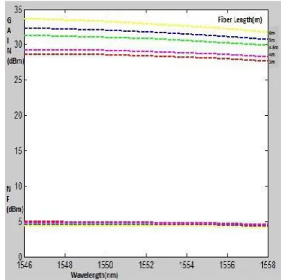
[image:3.595.71.256.479.719.2]to 6m the gain and NF is observed. This comparison follows the same phenomena, as the length of the fiber is increased the gain is obtained whereas NF also gets increased as well. But the optimized value of the length is obtained for most equalized channel is 5.75m having noise Figure of 0.2134dB.
[image:4.595.117.476.145.505.2]Figure 5 shows the results obtained from optical spectrum analyzer in the Opti System software. It displayed a clear view about the gain flatness obtained for different pump power (80mW, 100mW, 120mW, 150mW). The better outcomes results for -23dBm NRZ modulated signal having power 100mW while the power of 150mW represents the worst case causing an unequalized gain.
Figure 5. Output power (red) and Noise power (green)
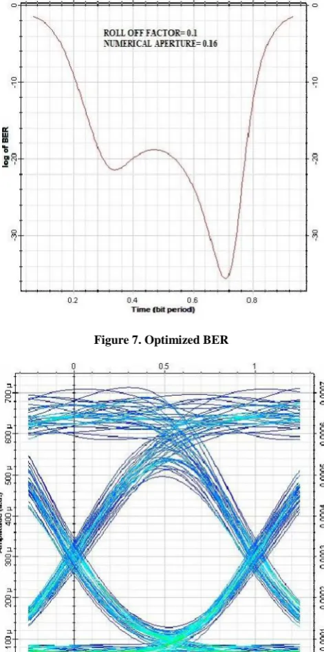
[image:4.595.141.450.529.750.2]Figure 6 shows comparative study about bit error rate (BER) measurement of the system. This shows for the previous optimized case that is fiber length 5.75m, pump power of 100mW, the numerical aperture of the fiber and roll off factor of the filter dominates the BER performance of the whole system. For a 2nd order low pass filter having roll off factor of 0.1 performs well than a roll off factor of 0.2. Low numerical aperture signifies less no of optical signal can pass through the fiber causing a significant level of BER at the output. The usual BER is found to be in the range of 10-25. The optimized design parameters are fiber length 5.75m, pump power 100mW, numerical aperture 0.16, roll off factor 0.1 and BER of 2.43x10-36.The final optimized BER performance of the whole system is shown in Figure 7.
Figure 7. Optimized BER
Figure 8. Eye pattern of the system
The performance of the system is analyzed using eye pattern for the channel 1 gives a big eye opening which means that the inter symbol interference (ISI)is low. The width of the opening indicates the time over which sampling for the detection is performed. The optimum sampling time corresponding to the maximum eye opening yields the greatest protection against noise. This system shows an average BER of 10-30 for channel 1. Figure 8 shows the eye diagram pattern of 16 WDM channels of optimized BER of 10-36.
Conclusion
The population inversion can be controlled by optimizing fiber length and injected pump power to EDFA. The optimum fiber length is 5.75 meter and pump power is 100mW. The system for 16 channel amplification was designed for gain of 29.61dB-30.401dB from 1546nm-1558nm band of wavelength with noise figure (NF) <5.5dB. The WDM system has a good Bit Error Rate in the range of 10-36.
REFERENCE
Bouzid, B. “Behavioral Variations of Gain and NF Owing to Configurations and Pumping Powers”, Optics and Photonics Journal, 2012.
Kaler R. and R.S. Kaler,’’ Gain and Noise figure performance of Erbium doped fibre amplifiers (EDFA) and compact EDFAs”, pp. 440-443, Elsevier, 2011.
Keiser G. “Optical Fiber Communication”, Third Edition, 2000.
Mahad F. D. B. and A. S. B. Mohd Supa,’’ EDFA Gain Optimization for WDM System”, vol. 11, no. 1, pp. 34-37, ELEKTRIKA, 2009.
Modeling, Simulation and gain flattening improvement for an erbium doped fiber amplifier, Barisaltiner, N. Ozlem unverdi, IEEE, 2009.
Nakaji H.,“Lossless dispersion compensating fibre module for wavelength-management networks”, Vol. 40, No. 12, June 2004.
Schiopu P. and F. Vasile,” The EDFA Per formance with gain versus pump power”, IEEE Semiconductor Conference, vol. 1, 2004.
Su, S.F. et al.“Flattering of erbium doped fiber amplifier gain spectrum using an Acusto-optic tunable filter.
Tachibana, M. et al. ”Erbium Doped Fiber amplifier with flattened gain spectrum”, IEEE photon, Tech Letter 3,118,1991.
VasileF. and P. Schiopu,” The signal and pumping power for EDFA”, IEEE Proceedings of the 2003 International Semiconductor Conference CAS, Sinaia, pp. 175-178, 2003.
Wikipedia web site.
Yoshida, S., S. kuwano, KIwashita, Electron letter,1995.