Tri-copter Drone Modeling with PID Control Tuned by
PSO Algorithm
Nada M. Ali Ahmed
University of Baghdad College of Engineering Electrical Engineering Department
Muna Hadi Saleh
University of Baghdad College of Engineering Electrical Engineering Department
ABSTRACT
The tri-rotors1 are more recent kinds of drones, as compared with the mostly used quad-rotors1 because of the numerous special characteristics over the other types of multi-copters. Many technical features specialize tri-copters like small volume that is useful in slender places, light weight, extended battery existence, and agility in translation and turns. In this paper, (single tri-rotor) design is theorized and the nonlinear mathematical model is derived completely by Newton-Euler formula then the Proportional1-Integral1 and Derivative1 (PID) controller1 is utilized to control the rotational and translational equations1, six PID controllers are used for six Degrees of Freedom (DOF) equations of the model with the associated parameters are tuned by Particle1 Swarm1 Optimization1 (PSO) method to minimize the whole Integral1 Time1 Absolute1 Errors1 (ITAEs) for the tri-rotor model and the effects are gained by Simulink1 in MATLAB1. The results were satisfactory with the stability of the system and with little delay."
Keywords
Tri-rotor, Particle Swarm Optimization algorithm, Integral Time Absolute Error, Proportional-Integral-Derivative control, Cost Function
1.
INTRODUCTION
Generally, Unmanned Aerial Vehicles (UAVs) can be flied autonomously or remotely and it can transfer payloads depending on the power plant of the vehicle. One of the UAV types is the Vertical Take Off and Landing (VTOL) which is capable to do some different movements such as hovering, vertical take-off and landing from dynamic or static place, lateral movement. Multi-rotors are VTOL vehicles under the UAV classification that have lately developed. Such multi-rotors make use of multiple multi-rotors to operate [1]. Recently, multi-copters such as tri-copters, quad-copters, and penta-copters have become very famous Unmanned Aerial Vehicles (UAVs) that is known commercially as drones and they are attracting much interest among amateurs, and engineers. Multi-copter is a vehicle with further than two motors without an aircrew on board [2]. The Tri-Rotor drone is a modern multi-rotor UAV type used in many applications such as target acquisition, reconnaissance, battle damage assessment, monitoring, imaging of forest fires, transportation, and many dangerous tasks [3]. There are some motivations that Tri-rotor is chosen over quad-rotor such as [4]:
I. A clear alignment in the long distances of the tri-rotor contrast to the quad-rotor type, which is dissipated at long distances.
II. These tri-rotors are flying at a professional speed and similarly to fixed-wing UAVs.
Tri-rotor UAV is assumed to be nonlinear system, rigid body that can be defined by body frame reference and global (earth) frame reference and this UAV type has three motors such that each motor is placed on each arm which has an equal length to the center of gravity [5]. In addition, a servo motor is fitted on the tilt arm to rectify the generated reaction torque, this design made the tri-rotor movement excellent especially in back turns. Tri-rotor has a huge studies place as it has large variations to different other multi-copters in model and control attitude and position due to its unique yaw motion trouble caused by the unpaired rotor in the tail [3]. To overcome for this problem, more than one design solution has been offered to control the yawing.
The first design is called (single Tri-rotor), in this design three rotors are placed on the three arms and a servo rotor is placed with the tail motor in order to incline it by a specific angle to minimize the reaction torque, this design is characterized by the ease of movement of the aircraft, especially in the turns, this design is used in this work. The second design is called (coaxial tri-rotor), in this design six rotors has been used such that every two counter rotating motors are positioned on one arm to terminate the generated reaction moments, this design is characterized by high stability [6]. In this paper, the mostly used linear PID1 controller is used with Particle1 Swarm1 Optimization1 (PSO1) tuning method. PSO1 is utilized to optimize the PID1 controllers’ gains.
The PSO1 algorithm1 was firstly offered by Kennedy1 and Eberhart1 in 1995. These theory concepts depend on the behavior of groups such as bird, ants or bees. Its technique is based totally at the concept of looking the nearest route to food in the cluster, if a specific particle discovers the best route, the alternative particles also will observe the same route to the meals even though their localities are some distance away from the meals [7]. In [5], tri-copter model is illustrated with using a PID control for angular velocity, altitude, and Euler angles. In [6], the two single and coaxial tri-rotor designs are introduced with a PID1 control to improve altitude and attitude stability, the simulations have been done in MATLAB for both designs with good obtained stability results.
set of rules and applied to the tri-rotor, finally sections five and six survey the simulation results and deduction.
2.
TRI-ROTOR VEHICLE’S FLIGHT
CONCEPTS
[image:2.595.61.247.175.315.2]Tri-rotor has been made up of a triangular frame with three rotors, the front rotors rotates oppositely while the tail rotor rotates as the same as the front left rotor as shown in Figure 1 [6]
Fig 1: Tri-rotor principles [5]
As any UAV, the tri-rotor has six degrees of freedom and four control actions can be controlled directly, first control action is the altitude which is created by increasing or decreasing the angular velocities for all brushless motors equally as shown in Figure 2-a. Second control is the roll moment which is accomplished by varying the angular velocities of the front rotors with numbers 2 and 3 while rotor number 1 is fixed as shown in Figure 2-b. Third control is generated by varying the angular velocity of rotor1 and fixing the front rotor angular velocities to give the pitch movement as shown in Figure 2-c. Fourth control is the yaw moment and it is obtained by orientating the servo motor in the tail by a small angle as shown in Figure 2-d. The tri-rotor can fly ahead by means of reducing speed of the front rotors and increasing speed of the tail-rotor so to incline the frame of the plane forwards, and it will be flown to right1 side1 by speed up the left rotor and slow down the right1 rotor1 and vice1 versa1 [9].
Fig 2: Control actions of Tri-rotor UAV [6]
3.
TRI-ROTOR MATHEMATICAL
MODEL DERIVATION
Y shape tri-rotor is presented in this work with three arms separated by an angle 120°. Any flying multi-copter is defined as rigid body and it is designated by motions with six1 degrees1 of freedom1 (DOF1). This tri-rotor1 model is derived via Newton’s second rule. The UAV system defined by three translational motion of body (local1) and earth (global1) coordinate1 systems1 equations and three rotating motion equations. Any point must be described with the aid of the coordinate system that is comprised as will be illustrated in Figure 3. The body1 coordinate1 expresses the placement of the tri-rotor1 and the earth coordinate1 expresses its place in the area. In order to translate between the two systems, a rotation matrix is needed which is described by this equation:
=
=
(1)
Where:"
, and --- are "Euler angles."
A. --- signifies "rotation of x-axis via an angle ."
--- signifies "rotation of y-axis via an angle ."
[image:2.595.310.558.242.609.2]--- signifies rotation of z-axis via an angleΨ."
Fig 3: Body (B) and global (G) coordinate systems of a UAV
Here are three external separated forces acted on tri-rotor body ( , , ) and three induced separated moments ( , , ) which can be described by these equations:
=
[image:2.595.321.537.436.608.2] [image:2.595.53.276.511.701.2]
Where:
"Denotes the external1 force1 vector1 performing on
the body."
, "Denotes the external forces performing on the body in the
and
axes respectively.
"
Denotes the forces produced from three
motors.
"Denotes the incline "angle of the servo motor." "Denotes the vertical control action.
= =
(3)
= (4) = for = 1, 2, 3. (5)
Where:
denotes the external moment vector performing on
the tri-copter body.
Denotes the length from the motor to the center of gravity."
Denote torques caused from the motors.
Denote attitude control actions.
Denotes the rotational velocity of rotor i.
Denotes the thrust constant.
Denotes the torque constant.
Newton second’s law states that the mass multiplied by time derivative of the translational velocity vector equals to the force vector as illustrated by the following equations:
(6)
= * +
(7)
I
+
(8) Where1:
m Denotes the mass of Tri-rotor."
V Denotes the translational speed vector."
g Denotes the gravitational force."
Denotes the rotational speed vector."
I Denotes the inertia matrix."
I=
(9)
=
(10)
=
(11)
"It is considered that Euler angles, and body angular rates are in hovering position, so the translational equations1 are obtained as follows1:"
(12)
(13)
(14)
And the rotational equations are illustrated as follows:
(15)
(16)
(17)
4.
PID CONTROLLERS TUNED BY
PARTICLE SWARM OPTIMIZATION
METHOD
The PID control is commonly used controller in many industrial uses due to its easiness and good performance for several structures. Six1 PID1 controllers are projected for the Tri-rotor1 UAV. The common PID1 control equation is represented as follows:
The proportional factor (K_p ) influences the system1 by reducing the rise1 time1, the integral1 factor (K_i) decreases the steady1 state1 error1 but, it will decelerate the transient response, and finally the derivative1 factor (K_d) drops the overshoot1 and improves the transient1 response1 that will stabilize the system1. These three1 constants of the PID control K_p ,K_i,K_d are tuned by the optimization method PSO to find the suitable values which will be applied to the tri-rotor to achieve stability and good flight [8]. Better performance and good stability can be obtained for nonlinear systems when the PID parameters are tuned by PSO. PSO technique is an optimization method which it is based in searching the optimum on social distribution of a swarm such as birds flocking or fish schooling. Each particle signifies a bird and the swarm define particles in the space [10, 11]. The particles in the swarm communicate through modification of velocity and position as the following equations:
= ⍵× + × (
- ) + × (
- ) (19)
= + (20)
⍵= –K( - )/Maxiter (21) Where:
=1 - swarm size(S)
= the iteration number.
= defines the velocity1 of parameter1 in particle1
at iteration.
⍵ = defines the inertia weight.
,
= 2,
= random1 numbers in the range1 (0, 1) =
defines acceleration factors.
= the best parameter1 in particle till iteration1.
= the best parameter1 until iteration.
= the position1 of parameter1 in particle at
iteration1.
= 0.9, = 0.4
Maxiter = the maximum number of executed iterations1.The
steps of PSO technique are given as follows:
1) At first step, the initialization of position and velocity for the particles in random is defined. 2) Initialize and .
3) Find the cost value for each particle and compare it with the previous and update with the better value.
4) Compare the cost value of each particle with the previous and update with the better value. 5) For each particle, update position and velocity. 6) Return to step (3) and repeat the procedure till
stopping condition is encountered.
[image:4.595.321.537.73.320.2]The stopping criteria can be selected either when the maximum iteration's number is reached or when there is no enhancement observed after a number of iterations. In this work, after 120 iterations no improvement in the objective function has been observed so the tuning process had been terminated. Six different PID controllers are proposed to the system to control both translational and rotational equations as demonstrated in Figure 4.
[image:4.595.55.280.84.290.2]Fig 4: Tri-copter model with tuned PID controllers
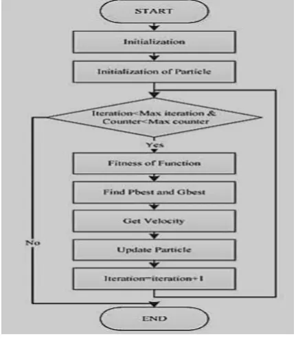
Figure 5 shows the flowchart for the PSO principle working, and the mechanism of PSO process in penetrating the multidimensional search area has been presented in Figure 6.
Fig 5: PSO Procedure Flowchart
Fig 6: PSO Mechanism in Searching Multidimensional Area
5.
SIMULATION RESULTS
The parameters used for the simulation illustrated in Table 1. The tri-rotor model is executed by means of Simulink in MATLAB environment, and the PSO procedure is performed by using m.file to achieve reiteration in calculations. ITAE for the sum of errors has been used as the objective function to be minimized because it produces less overshoot and oscillation than other criterions.
ITAE=
(22)
Where t =10 seconds (simulation time) and the error is expressed as:
= desired value – actual value (23) Euler angles are approximated near the hovering position and as follows:
[image:4.595.54.289.466.599.2]Table 1: The Parameters for Tri-Rotor Vehicle and the PSO Needed values
Parameter Mean Value Unit
Maxiter Maximum number of iterations
142 ---
S Swarm size 30 ---
D Dimension of particles (PID
gains)
18 ---
m Mass of Tri-rotor 0.814 Kg Ix Roll inertia 0.043 Kg.m2
Iy Pitch inertia 0.048 Kg.m 2
Iz Yaw inertia 0.077 Kg.m 2
g Gravitational force 9.8 m/sec2
l Arm length 0.15 m
[image:5.595.62.274.92.303.2]Figure 7 shows the objective function values obtained along the iterations. Clearly, there is no significant change after 120 iterations so the tuning had been stopped on the 142 iterations with minimum overall error. The acquired gains for PID controllers by using PSO optimization are specified in Table 2.
[image:5.595.64.272.96.301.2]Fig 7: The objective function with iteration number.
Table 2. The tuned gains for PID controllers
Gains X Y Z Ø θ
Kp 30.84 36.24 41.53 46.03 28.87 12.46
Ki 0.001 0.002 0.006 0.004 0.007 0.0002
Kd 6.736 7.72 10.53 15.8 19.56 7.128
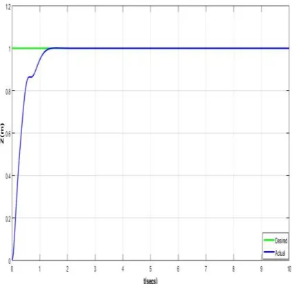
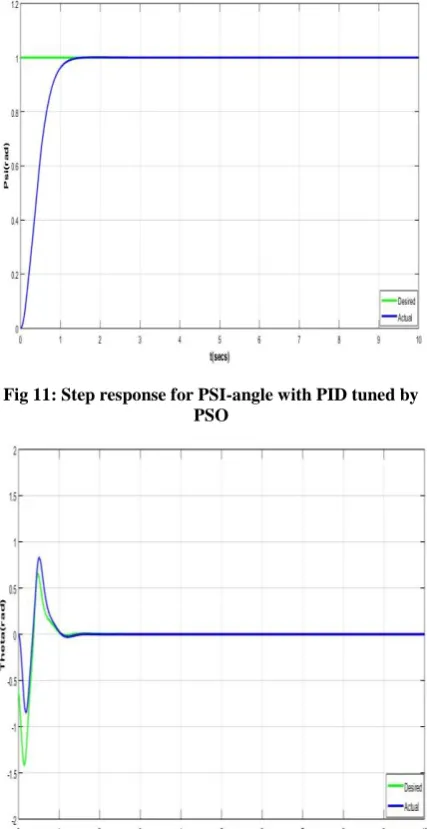
The desired inputs to x, y, z, psi axes were step input to check stability ,whereas and θ angles wanted values were acquired from x and y controllers since the system of the drone is under-actuated The obtained results are illustrated in Figures 8-13:
[image:5.595.318.527.257.490.2]Fig 8: Step response for x-axes with PID tuned by PSO
Fig 9: Step response for y-axes with PID tuned by PSO
[image:5.595.57.277.383.587.2] [image:5.595.324.536.525.731.2]Fig 11: Step response for PSI-angle with PID tuned by PSO
[image:6.595.62.274.75.275.2]Fig 12: Response for desired theta-angle with PIDtuned by PSO
Fig 13: Response for desired phi-angle with PID tuned by PSO
After applying the obtained gains from tuning, the ITAE values have been measured and the values were very small as the following:
ITAE for x-axes = 0.0994819 ITAE for y-axes = 0.1157421 ITAE for z-axes = 0.1056444 ITAE for phi-angle = 0.1397974 ITAE for theta-angle = 0.0852669 ITAE for psi-angle = 0.1365153
6.
CONCLUSION
The novel model, tri-rotor had been modeled in this paper with six DOF equations then after, the PID controllers were applied to the model in order to attain stability. The PSO technique was used to adjust the PID constants such that minimize the whole ITAE values for all the six errors. The results that were gained indicated less overshoot and small delay times so the tri-rotor will be in a stable manner when flying in hovering position and applying different tracks.
7.
REFERENCES
[1] B. H. Sababha, H. M. A. Zu’bi, and O. A. Rawashdeh, 2015. A rotor- Tilt-Free Tricopter UAV: Design, Modelling, and Stability Control, Int. J. Mechatronics Autom., Vol. 5, No. 2/3, pp. 107–113.
[2] O. Ayokunle, 2016. Simulation of a Tricopter UAV for Parcel Delivery with SimMechanics and SolidWorks3D, Researchgate.
[3] Z. Song, K. Li, Z. Cai, Y. Wang, and N. Liu, 2016. Modeling and Maneuvering Control for Tricopter Based on The Back-stepping Method, Proceedings of 2016 IEEE Chinese Guidance, Navigation and Control Conference, pp. 889–894.
[4] Ali, D. Wang, M. Aamir, and S. Masroor, 2017. Trajectory Tracking of a Tri-Rotor Aerial Vehicle Using an MRAC-Based Robust Hybrid Control Algorithm,
Aerospace, Vol. 4, No. 3, pp. 1–17
[5] S. K. Sai and H. M. Tun, 2015. Modeling and Analysis of Tri-Copter ( VTOL ) Aircraft, Vol. 3, No. 6, pp. 54– 62.
[6] D. Yoo, H. Oh, D. Won, and M. Tahk, 2010. Dynamic Modeling and Stabilization Techniques for Tri-Rotor Unmanned Aerial Vehicles, Int. J. Aeronaut. Sp. Sci., Vol. 11, No. 3, pp. 167–174.
[7] Singiresu S. Rao, 2009. Engineering Optimization: Theory and Practice.
[8] P Venkata Vishal, V. Natarajan, 2016. Control System Design for Tricopter using Filters and PID controller. [9] A. B. Arega, 2016. Design of Super twisting Sliding
Mode Controller for Hovering Stabilization of Tricopter UAV, M.Sc thesis, Addis Ababa University/Addis Ababa Institute of Technology.
[image:6.595.60.276.515.734.2]![Fig 1: Tri-rotor principles [5]](https://thumb-us.123doks.com/thumbv2/123dok_us/9295080.426743/2.595.310.558.242.609/fig-tri-rotor-principles.webp)