Volume 2010, Article ID 274935,13pages doi:10.1155/2010/274935
Research Article
Enhancing PMIPv6 for Better Handover Performance among
Heterogeneous Wireless Networks in a Micromobility Domain
Linoh A. Magagula, Olabisi E. Falowo, and H. Anthony Chan
Department of Electrical Engineering, University of Cape Town, Rondebosch 7701, South Africa
Correspondence should be addressed to Linoh A. Magagula,[email protected]
Received 8 October 2009; Accepted 24 June 2010
Academic Editor: Athanasios Vasilakos
Copyright © 2010 Linoh A. Magagula et al. This is an open access article distributed under the Creative Commons Attribution License, which permits unrestricted use, distribution, and reproduction in any medium, provided the original work is properly cited.
This paper analyzes the reduction of handover delay in a network-based localized mobility management framework assisted by IEEE 802.21 MIH services. It compares the handover signaling procedures with host-based localized MIPv6 (HMIPv6), with network-based localized MIPv6 (PMIPv6), and with PMIPv6 assisted by IEEE 802.21 to show how much handover delay reduction can be achieved. Furthermore, the paper proposes and gives an in-depth analysis of PMIPv6 optimized with a handover coordinator (HC), which is a network-based entity, to further improve handover performance in terms of handover delay and packet loss while maintaining minimal signaling overhead in the air interface among converged heterogeneous wireless networks. Simulation and analytical results show that indeed handover delay and packet loss are reduced.
1. Introduction
The rapid expansion of mobile wireless communications over the last few years has spawned many different wireless communication networks. These networks will be inter-connected and interworked with each other to offer access to Internet services for mobile users anytime anywhere. Also, the wireless mobile devices are becoming increasingly multimodal, containing multiple communication interfaces such as WLAN, WiMax, and UMTS [1] to access the different networks. Ultimately, the demands for users of the next generation networks to have ubiquitous and seamless access to internet services as they move around different access networks will be met. However, mobility management, in particular nonperceptible handover for active real-time applications such as VoIP, is still a challenge. The handover delay is still too large for time-sensitive services hence a lot of packets are lost during the handover procedures resulting in perceptible disruption to ongoing service sessions. Unfor-tunately, while mobility management protocols maintain the mobility bindings, they do not provide seamless handover in their current form [2].
Internet access ubiquity for mobile users requires seam-less mobility management supported by effective handover
mechanisms. These effective handover mechanisms ensure that ongoing communications are kept active with negligible perceptible disruptions during the handover procedures. Moreover, higher-layer connections such as TCP and UDP are defined with IP addresses of the communicating nodes, hence they break if a node changes IP addresses (e.g., due to mobility). Consequently, mobility resulting in handovers typically cause Layer 2 and/or Layer 3 IP mobility latencies and packet drops, thus disrupting current running services [3] and deteriorate quality of experience for the mobile user, particularly with time-sensitive services.
are utilized to optimize MIPv6’s performance in terms of reducing the handover delay and hence service degradation during the handover process. Generally, the main goal of localized mobility management protocols, for example, HMIPv6, is to reduce handover delay by localizing regis-tration hence reducing end-to-end delay so that seamless service continuity can be achieved. Unfortunately, since host-based mobility management schemes involve the mobile node (MN) in mobility-related signaling, they introduce more delay especially when the home agent (or its peers) is far away from the MN. Furthermore, they result in high packet loss, signaling overhead, power consumption, and extensive MIPv6 functionality in the IPv6 protocol stack [4]. Thus, there are still some challenges pertaining to reducing handover delay with the widely proposed host-based localized mobility management schemes.
However, it has been discovered that for handovers to be seamless, timely information accurately characterizing the network conditions is needed in order for appropriate actions to be taken [3]. Hence, IEEE recently published the IEEE 802.21 Media Independent Handover (MIH) services standard [8] to enhance handovers across heterogeneous networks. Unfortunately, MIH is a bulky standard that has to be incorporated in the MN protocol stack and hence adds some signaling overhead in the air interface, particularly when used with a host-based mobility management protocol. Recently, Proxy Mobile IPv6 (PMIPv6) [9] has been standardized by IETF [10] as a network-based localized mobility management protocol. Although PMIPv6 performs better than the popular host-based MIPv6 and its extensions in terms of handover performance [11], it still has a long handover delay that is not suitable for time-sensitive applica-tions. In PMIPv6 an MN can be provided service continuity without any mobility function [12] within itself. This feature makes it possible for any MN to be able to get mobility support from any network that implements PMIPv6, as long as the MN has the relevant network access interface and is authorized to get mobility services from that network.
Previously proposed handover solutions, either host-based or network-host-based, that enhance mobility management protocols introduce new functional elements either at the source access or target access or both source and target accesses to optimize handover performance in terms of handover delay and packet losses. However, these solutions require packets to be buffered at the source access or target access until the MN completes handover procedures. This means that during the actual handover process there is no real-time delivery of packets to the MN. Furthermore, adequate buffer space is required to store the packets during handover. However, as the MN performs the handover, the packets queued in the buffers overflow or get misordered and hence get dropped. Also, some packets get misrouted towards the old path which the MN has detached from and get dropped. Basically, these implementations result in abrupt disconnections from the source network hence perceptible disruptions to ongoing time-sensitive applications during the handover period.
Thus, the contributions presented in this work are (1) the analysis of handover delay for an IEEE 802.21-assisted
PMIPv6 architecture when compared with plain network-based PMIPv6 and host-network-based HMIPv6, (2) a complete enhanced handover process achieved through the introduc-tion of a new network entity, called the handover coordinator (HC), to operate in the overlapping region of interworking heterogeneous wireless networks in a PMIPv6 domain. This HC ensures that packets are delivered to the MN as real-time as possible even during the execution of the handover procedures. Ultimately, the HC enhances the handover performance by further reducing the handover delay and packet loss while maintaining minimal signaling overhead.
This paper focuses on improving the handover perfor-mance in micromobility domains because user mobility is higher in these domains hence frequent handovers occur and cause service disruptions, especially when the user moves to another subnet [13].
The rest of the paper is organized as follows.Section 2 gives a brief overview of PMIPv6. Section 3 presents the analytical comparison of handover delay performance in PMIPv6, HMIPv6, and the IEEE 802.21-assisted PMIPv6 schemes.Section 4presents and analyzes the PMIPv6 with Handover Coordinator architectural framework. The simu-lation scenario and results are presented inSection 5while
Section 6concludes the paper.
2. Overview of Proxy Mobile IPv6
PMIPv6 extends MIPv6 signaling and reuses many concepts of MIPv6 such as the Home Agent (HA) functionality.
Figure 1 below illustrates the relationship in terms of the
signaling paths for mobility-related signaling in network-based PMIPv6 and host-network-based MIPv6 domains.
PMIPv6 introduces two new network functional ele-ments called Local Mobility Agent (LMA) and Mobile Access Gateway (MAG) [9]. The LMA behaves like the HA of the MN in the PMIPv6 domain. It also has additional capabilities required for network-based mobility management.
PMIPv6 supports an MN in a topologically localized domain by utilizing the MAG entity. The MAG collocates with the access routers and handles mobility-related signal-ing on behalf of the MN. It tracks the movement of the MN, initiates the required mobility signaling, and ensures that the MN is authenticated before receiving network-based mobility services [9]. A tunnel is then established between the MAG and LMA so that the MN can be able to use the address from its home network prefix. Thereafter, the MAG emulates the MN’s home network on the access network for each MN.
MN MN Tunnel
Tunnel IP core
CN
PBU/PBA
BU/BA
MAGs Access router
Host-based MIPv6 domain
Network-based PMIPv6 domain
Figure1: Illustration of mobility-related signaling paths in PMIPv6 and non-PMIPv6 domains.
due to address configuration. Also, since a network element performs mobility-related signaling on behalf of the MN, PMIPv6 reduces the binding update delay by reducing the round-trip time, thus reducing handover latency.
3. Analytical Comparison of
Handover Delay Performance
3.1. Proxy Mobile IPv6. The typical signaling call flow dia-gram of handover in a PMIPv6 domain is shown inFigure 2. Notably, the binding registration messages are initiated from the MAG, which is in the network infrastructure, as opposed to host-based mobility management schemes such as HMIPv6 (as will be seen later) where the same signaling is initiated from the MN.
For clarity, the round-trip signaling call flow diagram showing the handover latency during MN handover to a new MAG in a basic PMIPv6 domain is shown in
Figure 3. Evidently, the handover delay in PMIPv6 is due
to many procedures that take place during handover: the attachment notification delay due to the event that informs the MAG of an MN’s attachmentDATTACH; the authentication delay (query(Q) and reply(R) messages) due to the MAG verifying if the attaching MN is eligible for network-based mobility management service DAUTH = DQ +DR; another authentication delay where the LMA verifies the authenticity of the MAG sending the proxy binding update
DAUTH 2=DQ2+ DR2; the proxy binding registration delay
DBINDING(PMIPv6) = DPBU+DPBAwhere the MAG performs
mobility-related signaling on behalf of the MN; the router advertisement delay DRA where the MAG advertises the necessary information, some of which is obtained from the LMA, for the MN to know its default access router; the actual IP configuration delay DCONF, and the duplicate address detection (DAD) delayDDAD. DAD is for checking if the local address configured by the MN is not already configured by another MN in the same MAG link. In fact,DCONFandDDAD
are not appreciable when the MN is already roaming in the PMIPv6 domain.
Delays are inevitable during vertical handover although they can be optimized or reduced (or made transparent to the active connections). The various delays during the handover process between MAGs in the PMIPv6 domain contribute differently to the overall handover latency. Hence, active real-time communication which an MN might be having with a correspondent node (CN) may be interrupted due to the handover latency which normally results in packet losses.
It should be appreciated that the handover delay is lower in PMIPv6 when compared to that in a host-based localized mobility management schemes by virtue of having the MN not getting involved in mobility-related signaling. That is, the binding update delay is shorter in PMIPv6 since it is carried out by a MAG (which is in the network infrastructure) instead of the MN which is usually further away from the LMA than the MAG is.
Also, since in a PMIPv6 domain the MN keeps its address configuration as long as it is inside the domain, the IP configuration and DAD process delays are negligible, unlike in host-based mobility management where these processes are performed completely anew every time an MN changes its point of attachment in the domain.
Thus, overall handover delay in basic PMIPv6 is the sum of the individual delay components:
DPMIPv6=DATTACH+DAUTH+DAUTH 2
+DBINDING(PMIPv6)+DRA. (1)
We assume that DATTACH=/ DRA since the router adver-tisement (RA) and MN attachment signals carry different messages hence are bound to encounter different delays.
Data flow
AAA query
AAA Reply
PBU
PBA AAA query
AAA reply
RA
Data flow MN detaches
MN attaches
LMA New MAG
Old MAG AAA server MN
Retains Address
A
u
th
en
ti
cation
an
d
bi
n
di
n
gr
eg
ist
ra
ti
o
n
Bidirectional tunnel Deregistration PBU
Deregistration PBA Bidirectional tunnel
Figure2: Signaling Call Flow of MN handover in PMIPv6 domain.
Dattach
Handover delay
Time
DQ DR DPBU
DQ2 DR2
DPBA
DRA New connection ready LMA
MAG
MN AAA/policy store
address uniqueness (LMA is assumed to have the overall knowledge of the PMIPv6 domain) and change its own link-local address if it detects a collision. ThusDDADis not appreciable.
3.2. Hierarchical MIPv6 (HMIPv6). Figure 4shows a typical signaling call flow diagram for a host-based localized mobil-ity management scheme, HMIPv6.
It is evident from the above figure that the MN is directly involved in mobility-related signaling. Therefore, the binding registration (BU and BA) time is longer in a host-based localized mobility management scheme than in a network-based localized mobility management scheme. We are assuming that both the PMIPv6 and HMIPv6 domains have single-level hierarchical structures, and only the MNs are mobile. Thus, DBINDING(HMIPv6) > DBINDING(PMIPv6), where DBINDING(HMIPv6) = DBU + DBA. Also, movement detection delayDMD =DRS+DRA andDDADare known to be long and time-consuming operations that can degrade handover performance significantly in host-based mobility management schemes as mentioned in [11]. Therefore,
DMD > DATTACH where DATTACH ≈ DRS(=/DRA). The
handover delay in HMIPv6 is
DHMIPv6=DMD+DBINDING(HMIPv6)+DAUTH
+DCONFIG+DDAD. (2)
Hence, in terms of PMIPv6 delay notation,
DBINDING(HMIPv6)≈DPBU+DPBA+DATTACH+DRAandDMD ≈
DATTACH+DRA. Of note is that according to [9] the MAG
in PMIPv6 only sends the router advertisement (RA) after completing the binding registration with the LMA, unlike in HMIPv6 where RA is sent to MN before binding registration. The handover delay in HMIPv6 in terms of PMIPv6 delay notation is
DHMIPv6=2DATTACH+ 2DRA+DBINDING(PMIPv6)
+DAUTH+DCONFIG+DDAD. (3)
Furthermore, an HMIPv6 mobility stack is added in the MN’s protocol stack as opposed to the PMIPv6 scenario where the addition of a mobility stack is not necessary as long as the MN roams within the PMIPv6 domain. This mobility stack adds complexity to the MN as well as signaling overhead in the air interface.
3.3. IEEE 802.21-Assisted PMIPv6 Scheme. The IEEE 802.21 MIH technology defines information exchanges that pro-vide topological and location-related information of service networks; timely communications of wireless environment information; commands that can change the state on the wireless link. In fact, these functions are provided by the Media Independent Handover Function (MIHF) which employs three functional components, namely, Media Inde-pendent Information Service (MIIS), Media IndeInde-pendent Event Service (MIES), and Media Independent Command Service.
MIIS provides static information about characteristics and services of the serving and neighboring networks. With
the necessary information, an MN may discover available neighboring networks and communicate with elements within these networks a priori to optimize handover. MIES offers services to upper layers by reporting dynamically changing lower layer events. These services are normally trig-gered by events which are based on reports on throughput, packet loss, signal strength, and so forth, of the lower layers. MICS is provided to the upper layers to enable them to control and manage the handover-related functions of the lower layers. In fact, the MICS commands are used to execute higher-layer mobility and connectivity decisions to the lower layers.
Thus, basically MIH services provide a report mechanism that conveys useful network status information to entities where a decision is made to cause a command to be executed at some specific network elements to facilitate seamless handover. Hence, the handover process is facilitated by the information provided from the network to the MN, in addition to the information that the MN collects from the lower layers. This cooperative information exchange enhances handover optimization.
With IEEE 802.21 MIH services, the MN and the PMIPv6 domain network entities, in particular the MAG in the access routers, are informed about the values of the relevant parameters necessary in handover decision making prior to the actual handover process. Furthermore, intelligent handover decisions to optimal subnets can be made with collaboration between the MN and the network entities. Thus, the MIH services enhance network discovery, prepa-ration, and selection. The IEEE 802.21-assisted PMIPv6 scheme exploits the services of the MIHF, in particular MIIS to reduce handover delay, for example, the access authentication delay component which can cause significant delay in network-based mobility management handovers.
MIH services enable some operations to be performed prior to the handover process while the MN is still connected to the old MAG’s link. Thus, when the handover is eventually performed, there will be fewer delay causing procedures executed. For example, the authentication delay is dealt with by enabling the new MAG to preauthenticate the MN ahead of time.
Utilizing the MIIS service, the MN and MAG get to know of their heterogeneous neighboring networks’ characteristics by requesting from information elements at a centralized information or MIIS server (which may collocate with a policy store and AAA server). The information server is assumed to be collocated with the LMA in this paper as shown inFigure 5.
The information elements in the server provide infor-mation that is essential for making intelligent handover decisions, such as, general information and access network-specific information (e.g., network cost, security, QoS capa-bilities, service level agreements, etc.), point of attachment specific information (e.g., proxy care-of-address, data rates, MAC addresses, etc.), and other access network specific information.
MN New AR MAP AAA server CN
RS
RA
BU
AAA request
AAA reply
BA
Data flow
IP
co
nfig
.
and
D
AD
A
u
thentication
and
binding
re
gist
ra
tion
Figure4: HMIPv6 domain handover signaling call flow.
LMA
MAG 3
MAG 2 MAG 1
IP core
Information server (MIIS server)
PoA PoA
PoA MIH-enabled
network
MIH MN
CN Internet
Figure5: IEEE 802.21-enabled PMIPv6 domain and Mobile Node.
the information server. Consequently, every MAG is always aware of its neighboring environment by utilizing MIIS to get information by requesting from the information elements in the central information server.
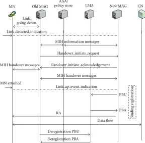
The MIH services, that is, MIES and MICS, are triggered by different dynamic events such as the attachment or detachment events of an MN in a MAG and varying handover decision-related parameters exceeding predefined thresholds. In particular, the MIES service notifies relevant handover decision engines about imminent handover while also updating the information server. Maintenance of the information server is very feasible since the localized PMIPv6 domain is possibly administered by a single operator or by cooperating service providers.
Assuming a trust relationship between the MAGs in the IEEE 802.21-enabled PMIPv6 domain and through the
utilization of proactive signaling deliberations via MIH services between the MAGs (on behalf of the attached MNs) and the Information server, a new MAG will immediately get information about MNs attaching to neighboring MAGs including authentication information. For example, when an MN is handing over from an old MAG (e.g., MAG 1) to a new MAG (e.g., MAG 2), then MAG 2 would already be having information about the MN ahead of time through the MIIS server. On obtaining the information from the server, MAG 2 authenticates the MN ahead of time in anticipation of a handover towards itself (MAG 2) in the near future. Thus, technically the MN is attached (hence, DATTACH →
B
inding
re
gist
ra
tion
PBU
PBA RA
Data flow
Old MAG LMA New MAG CN
MIH information messages
MIH handover messages
MIH handover messages
MN attached
Deregistration PBU
Deregistration PBA MN
AAA/ policy store
Handover initiate request
Handover initiate acknowledgement
Link up event indication Link
going down.
Link detected indication
Figure6: Signaling call flow for IEEE 802.21-assisted PMIPv6 handover process.
that MAG 1 has already authenticated the MN and sent the MN’s authentication information (with relevant cookies) and policy profile to the information server through MIH services since it (MN) is already in the PMIPv6 domain and receiving as well as sending information to correspondent nodes (CNs) before the handover.
Ultimately, the authentication procedure, as well as the attachment notification phase is eliminated from the actual handover process hence reducing handover delay. In that way, the actual handover will not be impeded by authentication and attachment delays. However, the early authentication process comes with the expense of reduced security. To increase the security provision, the authentica-tion procedure will have to be performed normally once the handover completes, and the MN has literally attached to the new MAG. To save resources, once an MN leaves the domain or becomes inactive for a certain predefined period, all its information is deleted from the information server.
Thus, from the above discussion we can deduce that the handover delay due to the IEEE 802.21-assisted PMIPv6 scheme is significantly reduced to
DPMIPv6(802.21)=DBINDING+DRA. (4)
A typical signaling call flow for the IEEE 802.21-assisted PMIPv6 is as shown in Figure 6. However, for clarity, the details of the involved specific MIH information messages and handover message primitives are not shown in the figure. Instead, they are collectively depicted as MIH information updates and MIH handover messages.
Thus, the reduced handover delay will ensure minimum service disruption for delay sensitive services.
In utilizing the MIH services, the authentication proce-dure is performed in the new point of attachment while the MN is still attached to its old MAG hence reducing handover delay which normally disrupts real-time service continuity during the actual handover. PMIPv6, on the other hand, reduces binding update delay hence ultimately reducing the handover delay. Unfortunately, signaling overhead in the air interface is sacrificed.
Having discussed an IEEE 802.21-assisted PMIPv6 scheme, which reduces handover delay and packet loss while trading-off signaling overhead during handover, we introduce a novel mechanism that enhances handover per-formance in terms of further reducing handover delay and packet loss while maintaining minimal signaling overhead.
4. PMIPv6 with Handover
Coordinator (PMIPv6-HC)
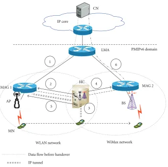
Figure 7 below depicts the architectural framework of
PMIPv6 with Handover Coordinator mechanism [15] to further improve handover performance.
WiMax network WLAN network
LMA IP core
MN
PMIPv6 domain
MAG 2 CN
HC MAG 1
1
3
2 4
6
5
IP tunnel
BS AP
Data flow before handover
Data flow after handover
Figure7: PMIPv6-HC architectural framework.
The HC has different functions that facilitate seamless handover with negligible handover delay and packet loss among the heterogeneous networks in the PMIPv6 domain. The functions include real-time data relaying, MN track-ing in the overlap region, and facilitation of MN pre-authentication and preregistration. Furthermore, the HC triggers relevant network elements in advance notifying them of imminent MN attachment or detachment. Thus, signaling steps during the actual handover are reduced hence reducing the handover delay and ultimately the packet loss.
Adding the HC as a stand-alone network entity is advantageous in that it reduces the impact of failure in the network. That is, the network will still run perfectly with its default mobility management protocol (e.g., PMIPv6) although with reduced handover performance if the HC fails. We assume that PMIPv6 is already implemented to support mobility among the heterogeneous networks in the domain. The HC is basically an added-value service that provides seamless and soft handover between the heterogeneous wireless networks. The partially overlapping networks utilize the services of this common network-based HC to achieve seamless handover between them.
Since the HC is network-based, it provides a handover solution that enables easier implementation of handover
policies by operators and providers based on business and operational requirements. For example, network operators are able to easily manage handovers while ensuring proper traffic load balancing. After all, operators who have the ability to switch a user’s session from one access technology to another can better manage their networks and better accommodate service requirements of their users [16].
The HC coordinates handover activities for the MN by communicating with both the old MAG (e.g., MAG 1) and new MAG (e.g., MAG 2) when the MN enters the overlap region. Thus, it performs handover functions on behalf of the MN. Normally, an MN attaches to a MAG through connect-ing to an access point (AP) or base station (BS). However, for simplicity, in this paper we omit the mentioning of AP or BS. The implementation of the PMIPv6-HC handover scheme is focused mainly on the proof-of-concept in terms of demonstrating the capability of the scheme to reduce handover delay and packet loss without incurring extrasig-naling overhead in the air interface. Thus, network discovery and selection, for example, in a scenario where there are more than two overlapping access networks (MAGs) in the heterogeneous network, have not been considered.
When the MN is attached to MAG 1, as shown in
to the MN as shown by step 1. As the MN gets further away from MAG 1 and enters the overlap region, it starts observing alink going downevent with respect to the signal strength from MAG 1 and hence realizes that a handover is imminent. At this predefined threshold (threshold 1), the MN generates a handover trigger signal which it sends to the HC via the currently attached network (the MN still has enough strength to send this signal). The IP address of the HC is either configured by the operator in the MN or is discovered through DHCP or obtained through periodic advertisements by the MN in the overlap region. The overlap region is the vicinity of operation of the HC.
The HC is carefully configured with specially set power levels to cover the overlap region. When the HC receives the signal from the MN via MAG 1, it automatically knows that the MN is about to handover to another access network (e.g., MAG 2’s WiMax access). Thus, the HC requests MAG 1 (as illustrated by step 2) to send subsequent incoming packets destined to the MN via itself (HC). In effect, the HC can also be seen to extend the signal range of MAG 1 just enough for the MN to continue receiving packets as real-time as possible and without errors as it traverses the overlap region. The HC establishes a communication with the MN through an IP tunnel via the corresponding interface (e.g., AP) and uses PMIPv6 functionality to coordinate the initiation and preparation of handover procedures among the respective MAGs in the background. Subsequently, MAG 1 forwards the packets destined to the MN via the HC which relays them in real-time through the IP tunnel to the MN (step 3) in the overlap region. The HC continues to track the MN, through link-layer mechanisms, for packet delivery as long as the MN is in its vicinity of operation, that is, the overlap area.
As the MN decapsulates the received packets in the overlap region it realizes that it is receiving them via the HC, hence automatically assured that a handover has begun. Thereafter, within a predefined short period it momentarily switches on (wakes up) its other interface resulting to the activation of the corresponding interface (e.g., BS) in the HC. Thus, the HC generates an imminent attachment notification signal which it sends to the next MAG (step 4). Note that the MN is still receiving data packets as real-time as possible via the HC while handover procedures are concurrently happening in the background.
On receiving the notification, MAG 2 is able to determine the MN’s identity (ID) based on the parameters in the received notification signal. Thus, MAG 2 uses the MN’s ID to start pre-authenticating the MN to verify its credentials.
Thereafter, MAG 2 associates its proxy care-of-address with the MN. This proxy care-of-address will be used at the LMA to reach the MN after handover. However, the LMA is updated with this proxy care-of-address only after a certain predefined signal strength threshold of the MN in the overlap region has been reached. Also, at this threshold (threshold 2), the MN gets deregistered from the old MAG (MAG 1). This threshold is experienced when the MN starts detecting alink upevent at a certain predefined signal strength level from MAG 2. Ideally, this threshold should be reached as the MN leaves the HC’s vicinity of operation. Thus, we have
two predefined thresholds; one is experienced when the MN enters the overlap area while the other is experienced when the MN leaves the overlap area. Their roles are reversed when the handover is towards the other direction. These thresholds are preconfigured in coordination between the relevant elements based on network conditions. However, other types of parameters can be used as thresholds, for example, cost, QoS, and so forth.
Basically, in terms of real-time packet relaying to the MN, the HC emulates MAG 1 when the MN moves from MAG 1 to MAG 2 while it emulates MAG 2 when the MN moves from MAG 2 to MAG 1.
Now, after assigning the new proxy care-of-address to the MN and performing proxy binding registration, the new MAG (MAG 2) acknowledges receipt of the imminent attachment notification signal by informing the HC that it is ready for the MN’s attachment. The HC receives the acknowledgement and waits for threshold 2 to be reached. Up until this point the MN receives data packets through its old interface via the HC. Once threshold 2 is reached, the HC quickly sends a signal to the old MAG notifying it to start performing the deregistration process of the MN from its binding list entries earlier than it would normally do without the HC, as illustrated in step 5. As MAG 1 deregisters the MN (and the old interface is switched offor put to sleep), MAG 2 and LMA simultaneously complete registration of the MN, and subsequently packet flow is redirected at the LMA as shown in step 6.
5. Simulation Environment and Results
5.1. Simulation Environment. The NS-2 network simulator with the NIST mobility package was used to carry out the simulations. Partially overlapping wireless access networks, IEEE 802.11 (WLAN) and IEEE 802.16 (WiMax), imple-menting PMIPv6, were simulated. An HC with carefully controlled power levels was placed in the overlap region of the networks and linked to the respective MAGs of these access networks. CBR traffic was transmitted using UDP to simulate real-time traffic, from a stationary CN outside the PMIPv6 domain to the MN through the LMA and MAG.
−0.5
Figure8: Throughput in ordinary PMIPv6 scenario.
−0.5
Figure9: Throughput in PMIPv6-HC scenario.
The start time of traffic flow from CN to MN was randomly changed; thus the start and end times of the handover process were not constant for different simulated handovers. Even though the times for handovers were different, the handover duration was observed to be the same. Similarly, the number of lost packets was the same in all cases for the different scenarios.
5.2. Simulation Results. Figure 8 below illustrates the throughput in the ordinary PMIPv6 scenario before and after handover while Figure 9 illustrates the same for PMIPv6-HC scenario before and after handover. Obviously, the networks have different characteristics and simulator settings, hence offer different throughputs.
As can be observed from Figure 8, the signal gets disconnected from the MN around 10.3 s resulting in packet loss (0 Mbps throughput) as the MN enters the overlap area (i.e., leaves the old network for the new network). The discontinuity corresponds to the period when handover procedures are performed, and the MN is unable to send or receive ongoing communication.
Figure 9below illustrates the behavior when the HC has
been incorporated in PMIPv6 in the handling of handover procedures.
InFigure 9, as can be observed, the handover happens at
around 10.8 s. That is because the HC acts as a real-time data relaying function or bridge of data packets destined to the MN when the MN is in the overlap area. Thus, because of the
10.2
1365 1385 1405 1425 1445 1465 1485 1505 1525 1545 Packet sequence numbers
Figure 10: Handover performance comparison of PMIPv6 and PMIPv6-HC.
HC there is no abrupt disconnection from the old network hence no severe packet loss is experienced. The glitch or spike observed around 10 s is when the packets to the MN started being forwarded via the HC. We can observe that the discontinuity or handover delay is very short in PMIPv6-HC. Likewise, the packet loss is very low compared to that experienced in PMIPv6.
Figure 10 below compares the corresponding handover
performance of PMIPv6 and PMIPv6-HC in terms of handover delay and packet loss as. Each point is an average of ten simulations.
As can be observed from Figure 10, PMIPv6-HC per-forms better in terms of both handover delay and packet loss. The HC ensures that packets continue to flow as real-time as possible towards the MN even during the handover process. The few packets that are lost are during the brief moment when the new MAG sends a router advertisement (RA) to the MN, basically enabling it to know its default proxy care-of-address. We have ignored packets that are lost due to overflowing queues since the CBR packet delivery rate remains constant yet the access networks differ. Thus, the graphs show packets that are lost during handover.
The following diagram,Figure 11, basically gives a clear perspective of the handover period during which the packets observed inFigure 10were dropped. We can observe from
Figure 11that the actual handover between the interworking
heterogeneous wireless networks start later in the PMIPv6-HC scenario when compared to the PMIPv6 scenario. This is due to the fact that the HC continues to relay ongoing communication packets to MN in the overlap region while with the PMIPv6 scenario the disconnection is abrupt hence happens earlier than that in PMIPv6-HC.
The discontinuities in Figure 11 depict the handover period during which no packets were received by the MN.
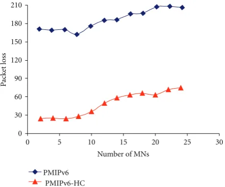
The following figures depict the handover performance of PMIPv6 and our proposed PMIPv6-HC when the number of simultaneously handing over MNs increases.
We can observe from Figure 12 that PMIPv6-HC per-forms better than PMIPv6. However, in both mobility management scenarios, the handover delay increases with the number of MNs. In fact, the increase is slight at fewer MNs and becomes significant as the number of simultaneously handing over MNs gets bigger. We can attribute this behavior to that increasing the number of simultaneously handing over MNs increases the mobility-related signaling messages that must be handled at the same time by the relevant network elements. This scenario overloads the elements hence cause delays in the processing of these signaling mes-sages. Furthermore, the increase of simultaneous signaling messages from the many different MNs increases the delay in the connection links due to the saturation in the channel. However, even in this situation the CN continues to send ongoing communication packets to the MN. Thus,Figure 13 below depicts the corresponding average packet loss.
The above figure shows the average packet loss experi-enced during handover as the number of MNs increases. As expected, the packet loss also increases with the number of MNs.
5.3. Signaling Call Flow. The signaling call flow diagram
in Figure 14 shows the typical signaling involved during
handover in the PMIPv6 with HC architecture. It can be observed that the no extrasignaling overhead is incurred in the air interface (between the MN and the network elements, i.e., MAGs and HC).
The data relaying capability of the HC ensures seamless and soft handover by enabling smooth disconnection from the old MAG hence very few packets are lost during the handover process. Furthermore, the proactive nature of the scheme in terms of preregistration, pre-authentication, and setting up the new PCoA ahead of time significantly reduces the effects of handover delay thus enhancing seamless service continuity.
To illustrate the handover delay improvement of the PMIPv6-HC scheme in terms of handover analytical perfor-mance modeling, we note that when PMIPv6-HC is used most of the handover activities that happen in ordinary PMIPv6 are initiated by the HC in the respective MAGs ahead of time on behalf of the MN while the MN is still directly connected to the old MAG or indirectly through HC,
0
Figure11: Handover delay in PMIPv6 and PMIPv6-HC.
0
Figure12: Impact of number of simultaneous handing over MNs on handover delay.
PBU/PBA De-registration MN
WLAN WiMAX Old MAG HC New MAG LMA AAA
Data flow over WLAN
Imminent handover notification (MN-ID, prefix, etc)
Authentication
PCoA ready Imminent handover notification reply
Update LMA
with PCoA PCoA update (PBU) PBU DeReg MN
Relayed data
Data flow over WiMax
PBA RA
Request to relay data Threshold 1
Threshold 2
Figure14: Typical Signaling call flow of PMIPv6-HC.
while moving towards the new MAG. Thus, the handover delay is substantially reduced to the time the MN receives its last packet from the HC until it receives its first packet in MAG 2, and this contribution is mainly due to the router advertisement delay, thus,
DPMIPv6-HC≈DRA. (5)
Note that by definition the handover delay is the time that elapses between the moment the MN receives its last packet from old access network (MAG 1) and the moment that it receives its first packet in the new access network (MAG 2), which is longer.
6. Conclusion
The paper first analyzed a handover mechanism that opti-mizes the PMIPv6 handover process with the assistance of the IEEE 802.21 MIH services. The analysis showed that PMIPv6, as a network-based mobility management protocol, performs better than host-based mobility management pro-tocols such as HMIPv6. Thus, PMIPv6 performs even better when assisted by the MIH services by employing proactive signaling deliberations which help to reduce the signaling steps during the actual handover process. However, it was noted that handover delay and packet losses are reduced at the expense of more signaling overhead in the air interface.
Thus, we further introduced a novel handover process where PMIPv6 was enhanced with a handover coordinator (HC) to further enhance the handover performance. With the HC being a network-based entity that coordinates the facilitation of handover activities on behalf of the
MN ahead of time, handover delay and packet loss were reduced without incurring extrasignaling overhead in the air interface. Furthermore, data packets were delivered to the MN as real-time as possible even during the actual handover period without any need for buffering either at the source or target access. The throughput rates observed during the handover period in the PMIPv6-HC scheme confirm the handover performance improvement of the scheme. Furthermore, the scalability of the proposed scheme in terms of its performance as the number of MNs that are involved in handovers at the same time increase was investigated.
For future work, the IEEE 802.21 MIH services may be incorporated to the HC to facilitate new target MAG discovery and network selection to further optimize the handover performance. To minimize signaling overhead in the air interface some of the MIH signaling may have to be delegated to the HC which would handle them on behalf of the MN.
References
[1] S.-J. Yoo, D. Cypher, and N. Golmie, “Predictive link trigger mechanism for seamless handovers in heterogeneous wireless networks,”Wireless Communications and Mobile Computing, vol. 9, no. 5, pp. 685–703, 2009.
[2] A. Dutta, V. Fajardo, Y. Ohba, K. Tanuichi, and H. Schulzrinne, “A framework of media-independent pre-authentication (MPA) for inter-domain handover optimization,” draft-irtf-mobopts-mpa-framework-05, work in progress, July 2007. [3] S.-J. Yoo, D. Cypher, and N. Golmie, “Timely effective
handover mechanism in heterogeneous wireless networks,”
[4] J. Kempf, “Problem statement for network-based localized mobility management (NETLMM),” IETF rfc-4830, April 2007.
[5] D. Johnson, C. Perkins, and J. Arkko, “Mobility support in IPv6,” IETF rfc-3775, June 2004.
[6] H. Soliman, C. Castelluca, K. El Malki, and L. Bellier, “Hierarchical mobile IPv6 mobility management (HMIPv6),” IETF rfc-4140, August 2005.
[7] R. Koodli, “Fast handovers for mobile IPv6,” IETF rfc-4068, July 2005.
[8] IEEE Std 802.21-2008, “IEEE standard for local and metropolitan area networks—part 21: media independent handover services,” January 2009.
[9] S. Gundavelli, K. Leung, V. Devarapalli, K. Chowdhury, and B. Patil, “Proxy mobile IPv6,” IETF rfc-5213, August 2008. [10] The Internet Engineering Task Force (IETF), http://
www.ietf.org/.
[11] K.-S. Kong, W. Lee, Y.-H. Han, M.-K. Shin, and H. You, “Mobility management for All-IP mobile networks: mobile IPv6 vs. proxy mobile IPv6,”IEEE Wireless Communications, vol. 15, no. 2, pp. 36–45, 2008.
[12] K.-W. Lee, W.-K. Seo, D.-W. Kum, and Y.-Z. Cho, “Global mobility management scheme with interworking between PMIPv6 and MIPv6,” inProceedings of the 4th IEEE Interna-tional Conference on Wireless and Mobile Computing, Network-ing and Communication (WiMob ’08), pp. 153–158, Avignon, France, October 2008.
[13] A. Diab, A. Mitschele-Thiel, and J. Xu, “Performance analysis of the mobile IP fast authentication protocol,” inProceedings of the 7th ACM Symposium on Modeling, Analysis and Simulation of Wireless and Mobile Systems (MSWiM ’04), pp. 297–300, Venezia, Italy, October 2004.
[14] C. M. Mueller and O. Blume, “Network-based mobility with proxy mobile IPV6,” inProceedings of the 18th Annual IEEE International Symposium on Personal, Indoor and Mobile Radio Communications (PIMRC ’07), Athens, Greece, September 2007.
[15] L. A. Magagula, H. Anthony Chan, and O. E. Falowo, “Handover coordinator for improved handover performance in PMIPv6-supported heterogeneous wireless networks,” in
Proceedings of the IEEE Wireless Communications & Network-ing Conference, (WCNC ’10), Sydney, Australia, April 2010. [16] K. Taniuchi, Y. Ohba, V. Fajardo, et al., “IEEE 802.21: media