Air Cooling of Mini-Channel Heat Sink in
Electronic Devices
Mousa M. Mohamed*, Mostafa A. Abd El-Baky
Mechanical Power Engineering Department, Faculty of Engineering, Minufiya University, Shebin El-Kom, Egypt Email: *[email protected]
Received January 2, 2013; revised February 2, 2013; accepted February 10,2013
Copyright © 2013 Mousa M. Mohamed, Mostafa A. Abd El-Baky. This is an open access article distributed under the Creative Commons Attribution License, which permits unrestricted use, distribution, and reproduction in any medium, provided the original work is properly cited.
ABSTRACT
Heat transfer experiments were conducted to investigate the thermal performance of air cooling through mini-channel heat sink with various configurations. Two types of channels have been used, one has a rectangular cross section area of 5 18 mm2 and the other is triangular with dimension of 5 9 mm2. Four channels of each configuration have been etched on copper block of 40 mm width, 30 mm height, and 200 mm length. The measurements were performed in steady state with air flow rates of 0.002 - 0.005 m3/s, heating powers of 80 - 200 W and channel base temperatures of
48˚C, 51˚C, 55˚C and 60˚C. The results showed that the heat transfer to air stream is increased with increasing both of air mass flow rate and channel base temperature. The rectangular channels have better thermal performance than trian- gular ones at the same conditions. Analytical fin approach of 1-D and 2-D model were used to predict the heat transfer rate and outlet air temperature from channels heat sink. Theoretical results have been compared with experimental data. The predicted values for outlet air temperatures using the two models agree well with a deviation less than ±10%. But for the heat transfer data, the deviation is about +30% to –60% for 1-D model, and –5% to –80% for 2-D model. The global Nusselt number of the present experimental data is empirically correlated as Nu0.052 Re Pr0.6 0.3 H w with
accuracy of ±20% for 3 10 3Re 5 10 4 and compared with other literature correlations.
channel heat sink. The results showed that significant
Keywords: Mini-Channel Heat Sink; Channel Air Cooling; Electronic Cooling; Fin Approach
1. Introduction
Traditional cooling by air is widely used in electronic devices in order to maintain it at acceptable temperature levels, e.g., below 100˚C. Recently, micro-channels heat sink is a very attractive method for high heat flux situa- tions due to its larger area to volume ratio [1]. Because of the wide range of uses for microchannel, it is important to be able to predict their behavior both thermally and hydro-dynamically [2]. Tuckerman and Pease [3,4] de- veloped the first microchannel water cooled heat sink, and demonstrated that extremely high power density with a heat flux as high as 7900 kW/m2 could be dissipated.
Many researchers have proceeded to study flow and heat transfer in microchannel in greater detail, as reviewed by Phillips [5], and they concluded that minimum thermal resistance was achieved by designing heat sink to allow for turbulent flow conditions. A number of experimental and theoretical investigations have been performed [6-12]. Among these, cooling by heat transfer to single
phase and boiling liquids flowing in microchannel is one of the promising directions. They had the potential prob- lem of large temperature variation at the base of channel heat sink. This temperature variation can be reduced by allowing more coolant to flow through the channels. However, this will require more powerful pumping power supply, generating more noise and requiring bulkier packaging. Missaggia and Walpole [13] introduced a heat sink with alternate water flow direction in adjacent channels, known as the single layer counter flow (SLCF) microchannel heat sink. Vafai and Lu [14] postulated a new concept of double layer counter flow (DLCF) mi- crochannel heat sink, which has two layers of heat sinks with the coolant in the top and bottom layer heat sink flows in opposite directions.
reductions in the total thermal resistance were not achieved by designing for turbulent flow, in contrast, higher pumping power resulted. A single and double layer counter flow micro-channels heat sink with rectan- gular channels have been modeled by employing the thermal resistance network to evaluate the performance of the heat sink [18]. Optimization results showed that both the single and double layer heat sinks operating in laminar flow out performed the heat sink under turbulent flow conditions, both in heat transfer and hydrodynamic considerations. The effect of channels number on thermal performance, thermal resistance and optimal geometry has been obtained [19]. The channel depth, the channel width and the fin thickness are varied under the con- straint that the channel aspect ratio should be less than 10. Among various design variables, the channel width ap-pears to be the most crucial quantity in dictating the per- formance of microchannel heat sink. The effect of tip clearance on the cooling performance was presented un- der the fixed pumping power condition [20], and the presence of tip clearance can improve the cooling per- formance when tip clearance is smaller than a channel width. In most of these studies [21-26], the fin approach is an effective tool to analyze the transport of heat in the microchannel heat sink by using both one-dimension and two-dimension models for heat transfer.
The objective of the present work is to investigate the th
2. Experimental Set-Up and Procedure
wn inric heater was used for heating the copper bl
Experimental Data Reduction
and channels surface ermal performance of mini-channel heat sink with rec-
tangular and triangular channels at various air flow rates and heating powers. The experiments were conducted in steady state at constant temperature of channel base and inlet air temperature. The heat transfer to the air flow and the heat transfer coefficient are examined. Fin approach of one dimensional, 1-D, and two dimensional, 2-D, models were used to predict the heat transfer and outlet air temperature from the channel heat sink. The experi- mental results were compared with the predicted ones by the two models to verify the fin approach models. An experimental correlation of global Nusselt number is targeted and compared with other literature correlations.
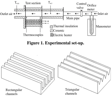
[image:2.595.309.539.522.720.2]The experimental facility and test section are sho
Figure 1. The compressed air was brought from two
large supply air tanks with a total volume of 8.65 m3 at a
discharge pressure of 8 bar. The tanks were provided with non-return valves on the supply pipes to control the pressure inside them. The air required for cooling process flows continuously from the main supply line to the test section through a steel pipe of 15.2 mm inner diameter and a control valve. The air flow rates were measured with an orifice meter which was checked for damage and calibrated before the installation. The test module was
fabricated from a copper block of 200 mm length, 40 mm width and 30 mm thick. Two types of 4 parallel channels were etched on the upper face of the copper block as shown in Figure 2. The first type is rectangular channels
with 18 mm in height, 5 mm in width and the plate or fin thickness is 4 mm. The second type is triangular channels with an isosceles triangle with a base of 9 mm and height of 10 mm.
An elect
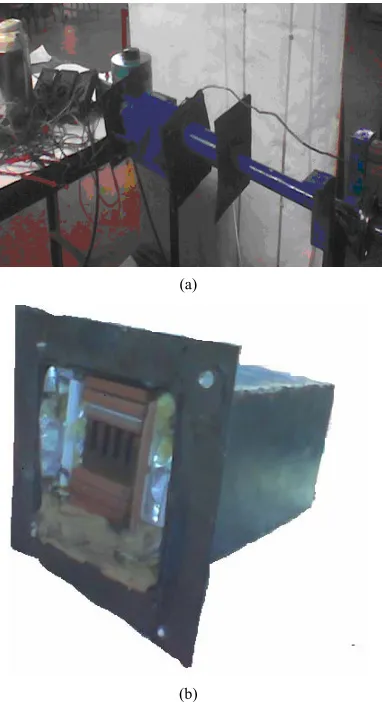
ock from underneath. The heater was formed as a coil around a ceramic plate and immersed between other two ceramic plates to avoid the electric shock. The upper face of the channels was covered by a ceramic layer and bolted to decrease the tip clearance to a minimum or neg- ligible value. The input power to the electric heater was controlled at 80, 120, 160 and 200 W with the aid of a voltmeter and an ammeter. The heating power was kept constant at certain value and the surface temperature was recorded when it became constant. The heater and heated channels were covered on the four walls by ceramic and thermal insulation to prevent leakage, and to minimize the heat transfer to the surrounding as shown in Figure 3.
The air temperature was measured at inlet and outlet of test section and at three positions underneath the chan- nels base. Thermocouples of type K were used for meas- uring. The thermocouples were attached to a digital multi-meter for measuring as illustrated in Figure 4. All
measured values of air temperatures and channels base temperatures were recorded at steady state.
The heat transfer between air flow
area can be considered as forced convection heat transfer. The top surface of its plate is insulated and the channels bases are uniformly heated and are considered at constant
Ta.i
Ta.o Test section Control
valve Orificemeter Outlet air
Main pipe
Manometer Inlet air
Thermocouples
Thermal insulation Ceramic Electric heater
Figure 1. Experimental set-up.
Rectangular channels
Triangular channels
(a)
[image:3.595.78.269.84.435.2](b)
Figure 3. Experimental facilities and test section.
Thermocouples
Digital voltameter
Ice-water solution Water bath
Temperature controller 20
200
18 12 4 5
20 10 10
60.0
[image:3.595.62.280.455.619.2]Dim. in mm
Figure 4. Thermocouples positions and rectangular channe
mperature. The air passing through the channels ab-
(1) Also, the average heat transfer per c
cu
l dimensions.
te
sorbs heat from the heated solid surface area. The total heat transferred to the air flow can be calculated as:
Qt m ca P a Ta o Ta i
hannel can be cal-
lated by:
c t
Q Q n (2) where, n is the number of channels. The average heat transfer coefficient can be calculated from the heat bal- ance between the channel heated surfaces and air flow as follows:
c e
c m
Q h
A T
(3)
where:
ln
s a o s a i m
s a o s a i
T T T T
T
T T T T
(4)
The Reynolds number and the channel hydraulic di- ameter can be calculated as illustrated in [1,21] as fol- lows:
Re h
s D m
A
(5)
4
2 2
s h
A D
w H
(6)
The average Nusselt number based on the experimen- tal data of average heat transfer coefficient and hydraulic diameter can be calculated as:
e h e
a h D Nu
k
(7)
The above relations were used to calculate the heat transfer coefficient and Nusselt number to investigate the effect of the channel opening ratio, w H, channel base temperature, and Reynolds number b on the channel hydraulic diameter on them.
ased
wo
3. Experimental Heat Transfer Analysis
The dimensions and channel opening ratio of the t types of channels used in this study are illustrated in Ta- ble 1. Because the upper face of the two types of chan-nels used is insulated by ceramic and thermal insulation, the heat transfer area, Ac, in rectangular channel is the channel base surface and the two sides. But for the tri- angular channels, Ac is that of the two isosceles surfaces of the triangle. The opening ratio, w H, for rectangular channels is the ratio between the ch width to depth. But for the triangular channels, the opening ratio could be assumed as the ratio between triangle bases to its height.
annel
able 1. The dimensions of the channels and their opening
pes L (mm) Dh (mm) As (mm2) Ac (mm2)
T ratios.
Channel ty w H
[image:3.595.309.536.690.732.2]The heat trans etw ir flow and c l su e ar
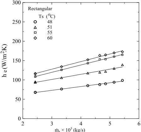
fer b een a hanne rfac ea at various air mass flow rates and channel base temperatures are illustrated in Figures 5 and 6. It is ob-
served that the heat transfer to the air, Qc, increases with increasing the air mass flow rates and hannel base temperatures, Ts. Obviously, the increase in heat transfer for rectangular channel is higher than triangular channel. The results of experimental heat transfer coefficient are indicated in Figures 7 and 8. The heat transfer coeffi-
cient is increased with increasing the air mass flow rates and channel base temperature. The effect of air mass flow rates on the heat transfer coefficient is slightly posi- tive increment, but the effect of channel base tempera- tures is highly positive effect.
c
2 3 4 5 6
0 5 10 15 20 25 30 35 40 45 50
Q
(W
)
Ts ( C) 48 51 55 60 Rectangular o
c
_
[image:4.595.312.536.86.296.2]ṁa × 103 (kg/s)
Figure 5. Effect of air mass flow on heat transfer for rec- tangular channel.
2 3 4 5 6
0 5 10 15 20 25 30 35 40 45 50
Q
(W
)
Ts ( C) 48 51 55 60 Triangular
o
c
_
[image:4.595.69.281.263.463.2]ṁa × 103 (kg/s)
Figure 6. Effect of air mass flow on heat transfer for train- gular channel.
2 3 4 5 6
0 50 100 150 200 250 300
h (W/m .K)
Ts ( C) 48 51 55 60 Rectangular
o
e
2
ṁa × 103 (kg/s)
Figure 7. Effect of air mass flow on heat transfer coefficient for rectangular channel.
2 3 4 5 6
0 50 100 150 200 250 300
h
(W
/m .K)
Ts ( C) 48 51 55 60 Triangular
o
e
2
[image:4.595.311.537.336.549.2]ṁa × 103 (kg/s)
Figure 8. Effect of air m at transfer coefficient
4. Mathematical Approach
heat flow ass flow on he
for triangular channel.
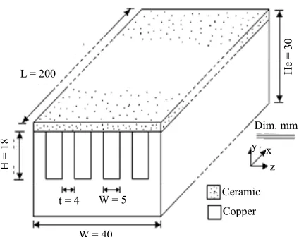
The problem considered is forced convective
through a rectangular channels heat sink as shown in
Figure 9. Each channel has a depth H, width w, length L, and the thickness of the fin is t. The direction of fluid flow is parallel to the x-direction. The channel bottom
y0
is kept at constant temperature
Ts and pro- y a constant heat flux from down, le the top surfacevided b whi
yH
is insulated. It is assumed that the width of t sink, W, is much larger than the channel width, w, and fin thickness, t. The analytical solutions of [image:4.595.69.277.503.701.2]W = 40 W = 5 t = 4
Dim. mm z x y Ceramic Copper He = 30 H = 18
[image:5.595.65.277.87.255.2]L = 200
Figure 9. Rectangular channel heat sink geometry and defi-
is problem in the literature are accomplished in two
4.1. Fin Approach of 1-D Model
-dimensional heat nitions.
th
ways only for rectangular channel. The first is fin ap- proach model and the second is porous medium model [21-25]. The interest in this work is focused on the fin approach model. So, the fin approach model in one di- mension, 1-D, and two dimension, 2-D, is used in this analysis.
The fin approach model used is one
conduction in steady state conditions and the heat flux is transferred to the air flow from any point on the fin sur- face [27]. In this analysis, the fin tip is adiabatic and ar- ranged in rectangular array. The total heat lost to the air flow can be calculated as:
t t o Tm (8) where, At is the fin surface area
Q hA
and channel base area. The overall efficiency of the fins array is calculated as:
1 f 1 o
t f
A NA
(9)
The single fin efficiency is also defined as follow:
tanhmH
f
mH
(10)
The parameter m is defined as:
2 f
s fs hP m
K A
(11)
The average air outlet temperature from the channel heat sink can be expressed as:
exp o ta o s s a i
p a hA
T T T T
mC
(12)
For fully developed turbulent heat transfer in a channel heat sink , the conventional form of the co
the Nusselt number as given in [27,28] to calculate the av
rrelations for
erage heat transfer coefficient, h ,can be expressed as:
4 5 0.4
0.023Re Pr
Nu (a) Ref. [24]
3 4 1 3
0.04 Re Pr
Nu (b) Ref. [21]
3Re 5 10 5
for 2 10 (13)
4.2. Fin Approach l
The fin model applied to the channel
nduction problem air temperature is
of 2-D Mode
heat sink is actually a one-dimensional steady state heat co
[21-23] as shown in Figure 9. The
averaged over the height of channel, with Ta Ta
x . So the air temperature Ta
x is the bulk mean tem- perature over the channel cross-section, y-direction. Ac- cording to the fin model, the variation of the t e T along the fin thickness is gov rned by,emperatur e
2 2 d 2 0 d a s T h T T K ty (14) where h is the interfacial heat transfer coefficient and K is the solid thermal conductivity.
boundary condition
s Subjected to the s
T T at y0 and d dT y0 at yH, Equation (14) can be solved [21,27,29] to get the fin temperature x, y as,
, cosh a T x y T xT T x
2
cosh 2
s a
Bi H y t
BiH t
(15)
The averaged fin thickness temperature is obtained as,
tanh
2
2
a s a
T x T x T T x
BiH t
BiH t (16)
where Biht Ks e cooling
is the Biot number, and the total heat lost to th air per unit length of the hea
obtained as:
t sink is
0 d d s t Tq x K
y
2 tanh 2
y
s s a
BiK T T x BiH t
(17)
The y-direction mean air temperature th channel is obtained as,
rough the
.
exp
a s s a i
T x T T T x L (18) Consequently, the av
erage air temperature inside the channel heat sink is obtained as:
1
1 exp
a a i s a i
where:
11 2 tanh 2 aC u Hp a m
L t w Bi BiH t
h
hannel heat sink should not be designed to be much longer than the characteristic length scale L* A computational program was developed accord th
(20)
The c
[21]. ing to e above procedures of the two models of fin to calcu- late the heat transfer to the air flow and the outlet air temperature from the channels heat sink and compared it with the experimental data at the same conditions.
5. Results and Discussion
The measured heat transfer data, Qc, and Ta.o of the air flow are compared with the estimated ones for 1-D
uations (8-13), and for by
model which was defined by Eq
2-D model which was also defined Equations (14-20), and the comparison is illustrated in Figures 10 and 11. It
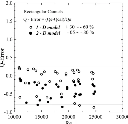
was found that, the deviation between measured heat transfer data, Qc, and the estimated one is about +30% to –60% for 1-D model, and +5% to –80% for 2-D model. The predicted values by 2-D model are larger than the experimental one. But for 1-D model, the predicted val- ues are about 50% larger than the experimental data; it means that the 1-D model is more stable than 2-D model. The estimated values of Qc by the two models used are dependent on the interfacial heat transfer coefficient, h, which was estimated from the Nusselt number by Equa- tion (7) and Equation (13) for circular tube and air duct respectively, which may be different than the channel heat sink model. So, the two models used give different predictions for the heat transfer data. For this reason, the correlation of Nusselt number used for fully developed
10000 15000 20000 25000 30000
Re
-1.0 -0.5 0.0 0.5 1.0 1.5 2.0
Rectangular Cannels Q - Error = (Qe-Qcal)/Qe
10000 15000 20000 25000 30000
Re -1.0
-0.5 0.0 0.5 1.0 1.5 2.0
T-E
rr
or
Rectangular Cannels
T - Error = (Ta.o-Tcal)/Ta.o + 10 % 1 - D model
2 - D model
-Figure 11. Deviation of measured data and calculated one for, Ta.o.
flow should be re-formulated to include the channel opening ratio, w H
unately, the deviation be .
Fort tween measured data of outlet air flow temperatures from the channel heat sink and the estimated one by the two models are very close to ±10%. So, the reliability of the two models to predict the temperature gradient and average temperature of the outlet air flow is very confident as shown in Figure 11.
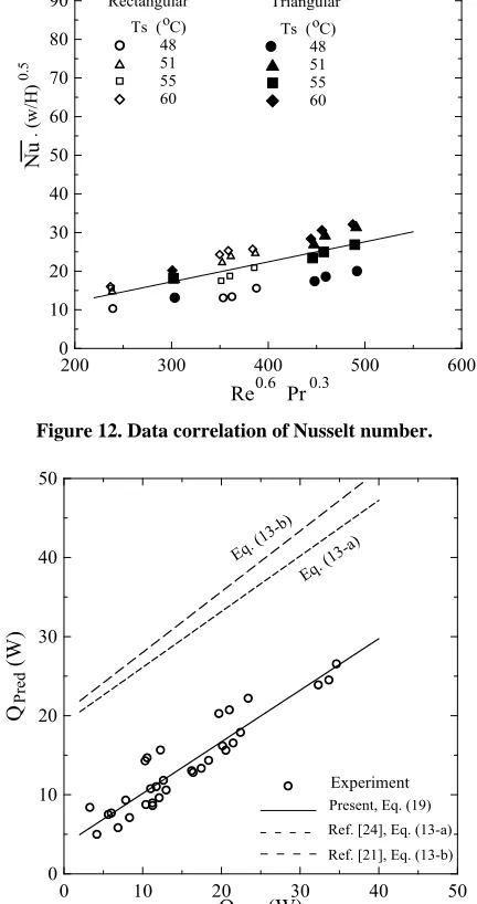
The dependence of Nusselt number on the Reynolds number and the channel opening ratio is shown in Figure 12. The increase in the Reynolds number leads to an in-
crease in the Nusselt number. At the same air mass flow rate, the heat transfer coefficient increased with increas- ing the channel base temperature. Consequently, the Nus- selt number increased systematically with increasing the channel base temperature for the two types of channels used.
Data Correlation
res 1 - D model
Q-Error
2 - D model
+ 30 ~ - 60 % - 05 ~ - 80 %
Figure 10. Deviation of measured data and calculated one for, Qc.
Present
Simple and purely empirical correlation for the Nusselt number of the p ent experimental data can be devel- oped and compared with other literature correlations in Refs. [21,27]. The experimental heat transfer data of Nusselt number can be best correlated using the least square method with accuracy of ±20% as the followings,
0.6 0.3
3 4
0.052 Re Pr
for 3 10 Re 5 10
Nu H w
(21)
[image:6.595.65.279.498.705.2]The comparison of the present experimental data cor- relation with other literature correlations is shown in
Figure 13. It is found that the deviation between the pre-
200 300 400 500 600 0
10 70
80 48
51
Re Pr 20
30 40 50
Nu
60
55 60
90 100
Ts ( C) Rectangular o
Triangular Ts ( C)o 48 51 55 60
. (w/
0.5
_
H
)
[image:7.595.75.281.86.287.2]0.6 0.3
Figure 12. Data correlation of Nusselt number.
0 10 20 30 40
Q (W) 50
0 10 20 30 40 50
Q
(W)
Present, Eq. (19) Ref. [21], Eq. (13-b)
exp
Pr
ed
Ref. [24], Eq. (13-a)
Experiment
Eq. (1
3-a)
Eq. (1
3-b)
Figure an
her l
is about 50% - 90%, because the channel opening ratio is not included in the previous correlations.
6. Conclusions
Heat transfer experiments were conducted to investigate the thermal performance of mini-channel heat sink. Two types of channels have been used with cross section areas of 5 18 mm2 for rectangular section and 5 9 mm2 for
triangular section. Four channels have been etched on copper block of 40 mm width, 30 mm height, and 200 mm length. The measurements were performed at steady state with air flow rates of 0.002 - 0.005 m3/s, heating powers of 80 - 200 W, and channel base temperatures of 48˚C, 51˚C, 55˚C and 60˚C. Analytical fin approach of
1-D and 2-D models were used to predict the heat trans- fer and outlet air temperature from channel heat sink, and compared with experimental data. The results are sum- marized as follows:
1) The heat transfer to air flow is increased with in- creasing both of air mass flow rate and channel base temperature.
2) The rectangular channels have higher heat transfer than triangular channels at the same conditions.
3) The predicted data of outlet air temperatures from channel heat sink for the two models of fin approach are very satisfactory with accuracy less than ±10%.
4) The deviation of predicted heat transfer is about +30% to –60% for 1-D model, and –5% to –80% for 2-D model.
5) The global Nusselt number of the present experi- mental data is empirically correlated by least squ
13. Comparison between the present correlation iterature correlations.
d ot
are method as, 0.052 Re Pr0.6 0.3
Nu H w for
4
Re 5 10
with accuracy of ±20%. 6) The present data correl
3
3 1
th other
0
ation is compared wi
correlations, and the deviation is about 50% - 90%, be- cause the channel opening ratio is not included in those correlations.
REFERENCES
[1] Jinliang X., Jijun Z. and Yunhua G., “Static and Dynamic Flow Instability of a Parallel Micro-Channel Heat Sink at High Heat Fluxes,” Energy Conversion and Management, Vol. 46, No. 2, 2005, pp. 313-334.
doi:10.1016/j.enconman.2004.02.012
[2] M. J. Kohl, et al., “An Experimental Investigation of Mi- crochannel Flow with Internal Pressure Measurements,” International Journal of Heat and Mass Transfer, Vol. 48, No. 8, 2005, pp. 1518-1533.
doi:10.1016/j.ijheatmasstransfer.2004.10.030
[3] D. B. Tuckerman and R. F. W. Pease, “High Performance Heat Sinking for VLSI,” IEEE Electron Device Letters, Vol. 2, No. 5, 1981, pp. 126-129.
doi:10.1109/EDL.1981.25367 [4]
5-3286. doi:10.1016/S0017-9310(02)00048-0
D. B. Tuckerman and R. F. Pease, “Ultrahigh Thermal Conductance Microstructures for Integrated Circuits,” Proceedings of the 32nd IEEE Electronics Components Conference,1982, pp. 145-149.
[5] R. J. Philips, “Micro-Channel Heat Sinks,” In: A. Bar- Cohen and A. D. Kraus, Eds., Advances in Thermal Mod- eling of Electronic Components and System, ASME, New York, 1990, Chapter 3.
[6] G. Hetsroni, et al., “A Uniform Temperature Heat Sink for Cooling of Electronic Devices,” International Journal of Heat and Mass Transfer, Vol. 45, No. 16, 2002, pp. 327
[7]
erns and Transitions in a Sma izontal,
Rectangular ids Engineering—
ASME, Vo 90.
Y. Cai, M. W. Wamdsganss and J. A. Jendrzejczyk, “Ap- plication of Chaos Theory in Identification of Two Phase
Flow Patt ll, Hor
[image:7.595.66.282.107.516.2]doi:10.1115/1.2817390
[8] Y. P. Peles, L. P. Yarin and G. J. Hetsroni, “Steady and Unsteady Flow in a Heated Capillary,” International Journal o
577-598. doi:10.1016/S0301-9322(00)00041-0f Multiphase Flow, Vol. 27, No. 4, 2001, pp.
[9] D. Brutin, F. xperimental Study
of Unsteady C eated
Mini-Topin and L. Tadrist, “E
onvective Boiling in H Chan- nels,” International Journal of Heat and Mass Transfer, Vol. 46, No. 16, 2003, pp. 2957-2965.
doi:10.1016/S0017-9310(03)00093-0 [10] H. Y. Wu and P. Chenh, “Visual
ments of Periodic Boiling in Silicon M
ization and Measure-icrochannels,” In- ternational Journal of Heat and Mass Transfer, Vol. 46, No. 14, 2003, pp. 2603-2614.
doi:10.1016/S0017-9310(03)00039-5 [11] W. L. Qu and I. Mudawar, “F
in Two Phase Micro-Channel Heat Sinks-I, Ex
low Boiling Heat Transfer perim
-3
ental Investigation and Assessment of Correlations Methods,” International Journal of Heat and Mass Transfer, Vol. 46, No. 15, 2003, pp. 2755-2771.
doi:10.1016/S0017-9310(03)00041
[12] S. F. Wang, R. Mosdorf and M. Shoji, “Nonlinear Analy- sis on Fluctuation of Two Phase Flow through a T-Junc- tion,” International Journal of Heat and Mass Transfer, Vol. 46, No. 9, 2003, pp. 1519-1528.
doi:10.1016/S0017-9310(02)00455-6
[13] L. J. Missaggiaand and J. N. Walpole, “A Microchannel Heat Sink with Alternating Directions of Water Flow in Adjacent Channels,” Integrated Optoelectronics for Com- munication and Processing, Vol. 1582, 1992, pp. 106-111. doi:10.1117/12.135008
[14] K. Vafai and Z. Lu, “Analysis of Two-Layered Micro- channel Heat Sink Concept in Electronic Cooling,” In- ternational Journal of Heat and Mass Transfer, Vol. 42, No. 12, 1999, pp. 2287-2297.
doi:10.1016/S0017-9310(98)00017-9
[15] X. Yin and H. H. Bau, “Uniform Channel Micro Heat Exchangers,” Journal of Electronics Packaging, Vol. 119, No. 2, 1997, pp. 89-94. doi:10.1115/1.2792225
pp. 4229-[16] C. Yang, D. Q. Li and J. H. Masliyah, “Modeling Forced
Liquid Convection in Rectangular Microchannels with Electro-Kinetic Effects,” International Journal of Heat and Mass Transfer, Vol. 41, No. 24, 1998,
4249. doi:10.1016/S0017-9310(98)00125-2
[17] S. F. Choquette, M. Faghri, M. Charmchi and Y. Asako, “Optimum Design of Microchannel Heat Sinks,” Micro- electro-Mechanical Systems DSC, Vol.
126. 59, 1996, pp. 115-
[18] S. H. Chong, K. T. Ooi and T. N. Wong, “Optimization of Single and Double Layer Counter Flow Microchannel Heat Sinks,” Applied Thermal Engineering, Vol. 22, No.
14, 2002, pp. 1569-1585.
doi:10.1016/S1359-4311(02)00083-2
[19] J. H. Ryu, D. H. Choi and S. J. Kim, “Numerical Optimi- zation of the Thermal Performance of a Microchannel Heat Sink,” International Journal o
Transfer, Vol. 45, No. 13, 2002, pp. 28
f Heat and Mass 23-2827.
doi:10.1016/S0017-9310(02)00006-6
[20] J. Y. Min, S. P. Jang and S. J. Kim, “Effect of Tip Clear- ance on the Cooling Performance of a Microchannel Heat Sink,” International Journal of Heat and Mass Transfer, Vol. 47, No. 5, 2004, pp. 1099-1103.
doi:10.1016/j.ijheatmasstransfer.2003.08.020
[21] C. Y. Zhao and T. J. Lu, “Analysis of Micro-Channel Heat Sinks for Electronics Cooling,” International Jour- nal of Heat and Mass Transfer,
4857-4869.
Vol. 45, No. 24, 2002, pp. 2)00180-1
doi:10.1016/S0017-9310(0
, No. 10, [22] S. J. Kim, D. Kim and D. Y. Lee, “On the Local Thermal Equilibrium in Microchannel Heat Sinks,” International Journal of Heat and Mass Transfer, Vol. 43
2000, pp. 1735-1748.
doi:10.1016/S0017-9310(99)00259-8
[23] S. J. Kim and D. Kim, “Forced Convection in Micro- structures for Electronic Equipment Cooling,” Journal of Heat Transfer—ASME, Vol. 121, No. 3, 1999, pp. 635- 645. doi:10.1115/1.2826027
[24] M, M. Mohamed, “Air Cooling Characteristics of a Uni- form Square modules Array for Electronic Device Heat Sink,” Applied Thermal Engineering, Vol. 26, No. 5-6, 2006, pp. 486-493.
doi:10.1016/j.applthermaleng.2005.07.013
[25] M. Beriache, A. Bettahar, H. Naji, L. Loukarfi and L. Mokhtar Saidia, “Fluid Flow
of a Mini Channel Heat Sink with Im
and Thermal Characteristics pinging Air Flow,” Arabian Journal for Science and Engineering, Vol. 37, No. 8, 2012, pp. 2243-2254.
doi:10.1007/s13369-012-0321-3
[26] X. L. Xie, W. Q. Tao and Y. L. He, “Numerical Turbulent Heat Transfer and Pressure
Study of Drop Characteris- tics in a Water-Cooled Mini channel Heat Sink,” Journal of Electronic Packaging, Vol. 129, No. 3, 2007, pp. 247- 255. doi:10.1115/1.2753887
[27] F. P. Incropera and D. P. DeWitt, “Fu and Mass Transfer,” Fourth Edition, John W
ndamentals of Heat iley, New
, Vol. York, 1996.
[28] R. W. Knight, J. S. Goodling and D. J. Hall, “Optimal Thermal Design of Forced Convection Heat Sinks-Ana- lytical,” Journal of Electronic Packaging—ASME 113, No. 3, 1991, pp. 313-321. doi:10.1115/1.2905412 [29] J. P. Holman, “Heat Transfer,” McGraw-Hill Book Com-
pany, New York, 1989.
Nomenclature
Ac: channel surface area, (m2)
As: channel section area, (m2)
At: total channels surface area, (m2)
Af: fin surface area, (m2)
Afs: fin section area, (m2)
Bi: Biot number, (–)
pecific heat, (J·kg–1·K–1)
Cp: s
Dh: channel hydraulic diameter, (m)
H: channel depth, (m) e: copper block height, (m) H
h: interfacial heat transfer coefficient, (Wm–2·K–1)
h: overall heat transfer coefficient, (Wm–2·K–1)
: thermal conductivity(Wm–1·K–1)
: channel or heat sink length, (m) *: characteristic length scale, (m)
: air mass flow rate, (kg·s–1)
K L L m
N: fins number
Nu: average Nusselt number, (–)
n: channels number Pf: fin perimeter, (m)
Pr: Prandtl number, (–) Q: heat transfer rate, (W)
Q: average heat transfer r
q: heat transfer per unit length, (W·m–1) Re: Reynolds number, (–)
T: temperature, (˚C)
T: average temperature, (˚C) t: fin thickness, (m)
: density, (kg·m–3)
Subscript
a: air c: channel cal: calculatedum: mean air velocity through channel, (m·s–1)
W: channel heat sink width, (m) w: channel width, (m)
f: fin efficiency
o: overall fins efficiency : viscosity, (N·m–2s)
e: experiment f: fluid, or fin i: inlet air o: outlet air
l s: surface or fin meta t: total