GraphOnn~
--
-GraphOn X terminals
bring your desktop
into the 1990's
GraphOn 14
User's Guide
First Edition
© GraphOn Corporation 1990 All rights reserved.
This manual may not be reproduced, in whole or in part, in any manner whatsoever, without the express written permission of GraphOn Corporation. Printed in U.S.A.
Part No. 901-0040-01
Specifications are subject to change without notice.
GraphOn is a trademark of GraphOn Corporation. UNIX is a trademark of AT&T.
X Window System is a trademark of MIT.
DEC, VT, LA, and LN are trademarks of Digital Equipment Corporation. Epson is a trademark of Seiko Epson Corporation.
HP, ThinkJet and LaserJet+ are trademarks of Hewlett-Packard Company. Okidata is a trademark of OKI America, Inc.
Summagraphics and Summamouse are trademarks of Summagraphics Corporation. OMS is a trademark of OMS, Inc.
Important Notice
Notice
Table of Contents
Chapter 1
Introduction
1.1 Terminal Features 1
1.2 The X Window System 2
1.3 How the X Window System Works 2
1.4 The GraphOn 14 Architecture 3
1.5 Understanding the Various Communications Protocols
Used by GraphOn 14 4
1.6 How to Run X on the GraphOn 14 5
1.7 VT220/VT100 Emulation 6
1.8 Miscellaneous Features. 7
1.9 What This Manual Contains 9
Chapter 2
Keyboard
2.1 General 11
2.2 Using the Keyboard in X. 12
2.3 Key Descriptions 13
Top Row Keys . 13
Extended Cursor Keypad 15
Numeric Keypad 17
Special Keys of the QWERTY Section 18
2.4 Keyboard Layout 21
2.5 Keyboard LEDs 23
2.6 Compose Character Tables 24
Chapter 3
Setup
3.1 Introduction 27
3.2 Using Setup Mode 30
3.3 Setup Mode Keys 33
3.4 Default Setup Configuration 35
3.5 Directory Setup . 36
3.6 General Setup . 38
3.7 Devices Setup . 39
3.8 Communications Setup . 44
3.9 Display Setup 48
3.10 Keyboard Setup 49
3.11 Memory Setup . 51
3.12 Alpha Setup 52
3.13 Function Keys Setup 59
Chapter 4
Using a Graphic Input Device
4.1 Introduction 63
4.2 Attaching an Input Device 63
4.3 Using an Input Device in X 64
4.4 Using an Input Device in VT220/VT100 Emulation 65
Chapter 5
Printing
5.1 General 67
5.2 Keyboard Print Functions 67
Print Key 67
Auto Print Mode 69
5.3 Cancelling a Print Operation 69
Chapter 6
Attaching Multiple Host Computers
6.1 Overview 71
6.2 Connecting the Host to Port B or Port C . 71 6.3 Communicating with Multiple Hosts 72
Chapter 7
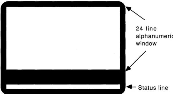
Status Line
7.1 General 73
7.2 Status Line Location 74
7.3 Current Terminal Status. 74
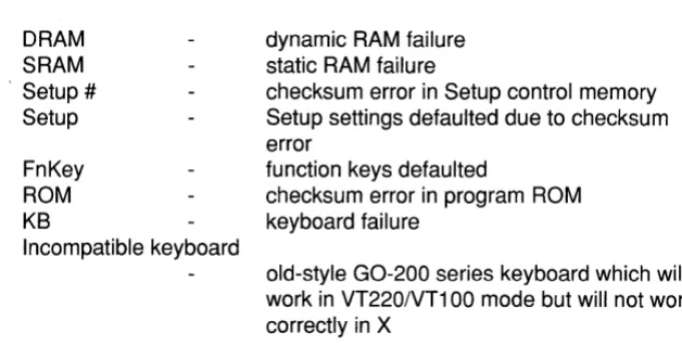
7.4 Error Conditions 77
Self Test Messages 77
Printer Warning Messages 78 Serial Port Receive Errors 79
Chapter 8
Communications
8.1 Overview 81
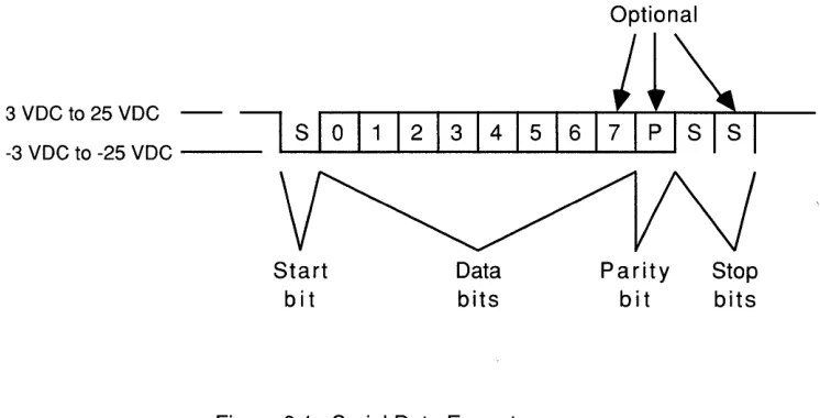
8.2 Serial Data Format 81
8.3 Serial Port Concepts 83
Generalized Device Connections 83
Input Buffer 83
Flow Control 85
8.4 Main Port Communications 86
Remote and Local Echo. 86
Hold Key 86
8.5 Printer Port Communications 88
Detecting Whether a Printer Is Attached 88
Flow Control 88
8.6 Serial Port Connector Pinouts 89
Port A 89
Port B 91
Appendix A
Installation
A.1 Setting Up the Terminal. 95
Unpacking 95
Site Considerations 96
Attaching the Keyboard. 96
Applying Power 96
Adjusting Screen Brightness 97
A.2 Connecting to Other Devices 98
Configuring the Terminal Using Setup Mode 98
Host Interface 99
Graphic Input Device Interface
99
Printer Interface. 100
Final Checkout . 100
A.3 Installing the X Window System. 101
Appendix B
Troubleshooting
B.1 Initial Power Up . 103
B.2 Diagnostics Failure 104
B.3 Host Communications 105
B.4 Printer Communications. 107
B.5 Alphanumerics . 110
B.6 Bringing Up X 110
B.7 Downloading Setup and Function Keys 111
Appendix C
Character Set Tables
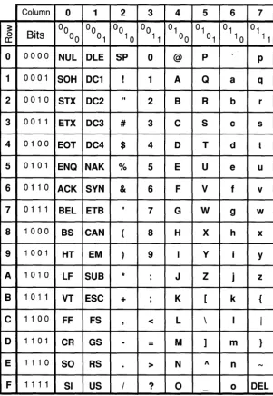
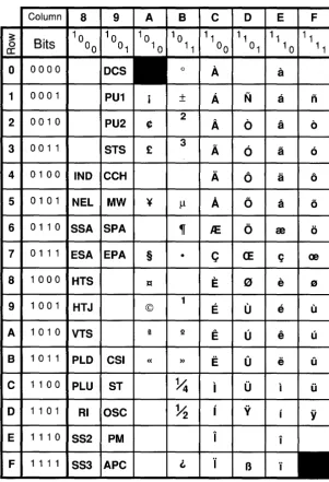
C.1 Overview 113
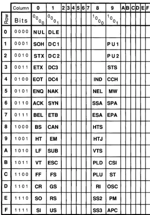
CO and C1 Control Codes 115
US ASCII 116
DEC Supplemental Graphics 117
UK ASCII 118
DEC Special Graphics 119
Monitor Mode Graphics . 120
Appendix D
Escape Sequences
0.1 VT220/VT100 Emulation Commands 123
0.2 GraphOn 14 System Commands 132
Figure 2.1 Figure 2.2 Figure 3.1 Figure 7.1 Figure 7.2 Figure 7.3 Figure 8.1 Figure C.1 Figure C.2 Figure C.3 Figure C.4 Figure C.5 Figure C.6 Figure C.7
Table of Figures
GraphOn 14 Keyboard Layout 22
Compose Character Tables. 25
Setup Screens 32
Status Line Placement 75
Status Line in VT220/VT100 Emulation 76
Status Line in X 76
Serial Data Format . 82
CO/C1 Controls 115
US ASCII (left half of DEC Multinational Set) . 116 DEC Supplemental Graphics (right half of DEC Multinational Set) UK ASCII .
DEC Special Graphics
Monitor Mode - $00 through $7F Monitor Mode - $80 through $FF
Table 7.1 Table 7.2 Table 8.1 Table 8.2 Table 8.3
Table of Tables
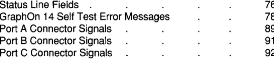
Status Line Fields .
GraphOn 14 Self Test Error Messages Port A Connector Signals
Port B Connector Signals Port C Connector Signals
76 78
89
Chapter 1
Introduction
1.1 Terminal Features
The GraphOn 14 offers these features:
• X Window System compatibility in conjunction with host-based X server software
• 800 x 600 resolution (expandable to 800 x 920 through software implementation)
• Sophisticated local mouse/digitizer support
• Raster Operators for font and bitmap manipulations • VT220 and VT100 emulation
• Up to 30 lines of text in VT emulation • General purpose communications ports
The GraphOn 14 system provides complete support of the X Window System Version 11 over an RS-232 serial communications line. This system consists of a GraphOn 14 display device and the GraphOn X Server Software running on the host.
This manual provides the information required to connect, configure, and use the GraphOn 14 display device.
The GraphOn 14 may communicate directly with a local printer to generate copies of either the graphics or alphanumeric display. In VT220/VT100 emulation, it may also act as a go-between, allowing the computer to transmit characters to the printer with or without the characters being displayed at the terminal.
1.2 The X Window System
The X Window System, also called X, consists of a display server program and a set of application program interface libraries that allow multiple applications running on multiple hosts to share a single display, each showing output in a different window on the screen.
Much of the importance of X is that it has been ported to a large number of systems. This allows diverse hardware platforms to provide a single, device-independent graphical user interface for application programs. This greatly simplifies the task of porting applications between different systems.
1.3 How the X Window System Works
X manages a screen, a keyboard and a mouse, making these resources
In practice, clients generally use a software "tool kit" to manage their dealings with X. These tool kits provide two main benefits. They simplify the
programming task for applications by hiding the low level details of X. And, by providing ready to use ''widgets'' such as scrotl bars and radio buttons, they help to enforce a consistent "look and feel" across many applications.
X is network transparent in that it can as easily handle display requests from co-resident processes as it can from processes executing on other systems networked to the host. Therefore, client processes may exist anywhere on the network, allowing the user to view multiple applications running on any number of hosts.
1.4 The GraphOn Architecture
The X server consists of two major sections - the device independent interface (dix) and the device dependent interface (ddx). The dix handles the high level functions of managing windows, communicating over networks, and parsing the X protocol. It is independent of the display hardware.
The ddx implements the device dependent functions required to support the windowing system. It draws lines and polygons, it performs the "raster
operations" which copy text and other rasters between the screen and off-screen memory and from screen to screen, and it manages the keyboard and mouse, reporting mouse position and up and down transitions of both keys and mouse buttons.
Every hardware manufacturer who supports the X Window System creates a ddx which drives its own implementation of screen, keyboard, and mouse. In
general, ddx and the dix are executed on the same processor.
This architecture yields important benefits in an X terminal. These become apparent when one considers the assumptions which the designers of X made regarding potential X-capable hardware platforms. First, X assumes that it will not run out of memory - so, either a lot of memory must be available, or virtual memory must be supported. Virtual memory is preferred, since the X protocol places no limits on the number of windows which may be opened.
Second, since fonts are managed by and accessible to the server alone and not to the clients, the server benefits from local access to a file system on disk where fonts may be stored.
Thus, it is very useful to have X running on workstations and other hosts which can provide virtual memory and local disk storage, which are not normally found in terminals.
Another benefit of the GraphOn architecture is simply that two processors do the work. Since the actual low level drawing tasks are performed by the processor in the display device, many of these tasks can be executed concurrently with other server functions executing in the host.
1.5 Understanding the Various Communications
Protocols Used
by the GraphOn 14
Although the GraphOn architecture uses RS-232 for communicating graphics commands to the terminal, this communications line usage should not be confused with the typical use of the local area network with the X Window System.
In a conventional X platform, a workstation runs an X server which drives its own display. Clients use standard operating system facilities which allow them to communicate with each other and with the X server. These facilities are just as comfortable communicating across a network as they are communicating locally. Thus, clients may run on any system on the network and communicate with the server over that network.
The RS-232 link is used by the X server to communicate its own protocol with the display device - the X byte-stream protocol does not traverse the serial line. In fact, the GraphOn 14 realizes significant speed improvement by transmitting compressed data to the terminal, rather than the raw X byte-stream.
The GraphOn 14 has full access to the network by utilizing the host system as a gateway onto the network. Full network support is preserved.
A significant benefit of using an optimized protocol on the RS-232 line is that it becomes possible to use X at relatively low baud rates in order to use a modem. Even 2400 baud communication, while perhaps not the ideal environment for running X, is useful and fully functional.
1.6 How to Run X on the GraphOn 14
As described above, the GraphOn architecture divides X into two pieces, with the bulk of the X server residing on the host. In order to run X, the GraphOn X Server Software must be installed on your host system. This software is available from GraphOn - if you don't have it, contact your GraphOn Sales Representative.
All files and documentation necessary to install, run, and learn about the X Window System on the GraphOn 14 are contained in the GraphOn X Server Software package. The manuals which come with the GraphOn X Server Software will step you through:
• loading the software on your host
• performing any system configuration necessary • starting the X server
1.7 VT220/VT100 Emulation
The GraphOn 14 provides full VT220 emulation and VT100 emulation in addition to its X support. It is provided for compatibility with systems which do not yet
have X capability, for applications which demand more rigorous VT220/VT1 00 emulation than is provided by X, and as the medium for logging on and starting up an X session.
To be precise, the alphanumeric mode of the GraphOn 14 is an emulation of either the Digital Equipment Corporation VT220 or the VT100 with Advanced Video Option and serial printer interface. The emulations are so complete that the GraphOn 14 is truly "plug compatible" with these terminals -the computer "thinks" that it is connected to a VT220 or VT100. All functions of these terminals are supported, which allows the user to access the full range of DEC-compatible software.
The VT220 emulation supports such features as a downloadable character set, selective erase, 8-bit control code support, and DEC's Multinational Character Set.
The VT100 emulation responds to commands from the host computer in the same manner as a real VT100. Of course, the GraphOn 14 supports the VT220's emulation of the VT100, as well.
1.8 Miscellaneous Features
General Purpose Serial Communications Ports
The GraphOn 14 provides three generalized RS-232 ports for serial communication with one or more of the following devices:
• computers
• output devices such as printers
• input devices such as mice and digitizing tablets
Since any type of device may be attached to any of the ports at the back of the GraphOn 14, these ports are labeled 'A', 'B', and 'C' rather than 'Main', 'Printer', etc. Setup mode provides the means of establishing which ports are attached to each type of device.
In addition to connecting any type of device to any port, devices of the same type may be connected. For example, it is possible to connect the terminal to two or three computers. All device connections are configured using Setup mode. Also, since the terminal can redirect 1/0 through any of the ports, it is a simple matter to redirect a screen dump away from the printer and back to the host computer instead.
Local Mouse/Digitizer Support
Raster Operators
1.9 What This Manual Contains
This manual is divided into a chapters.
Chapter 1 provides an introduction to the GraphOn 14.
Chapter 2 describes the various functions of the keys on the keyboard. Chapter 3 describes how to use Setup mode to configure the terminal.
Chapter 4 describes how to use a locally attached graphic input device such as a mouse.
Chapter 5 describes how use a locally attached printer.
Chapter 6 describes how you can attach more than one host computer to the terminal.
Chapter 7 describes the information displayed on the status line.
Chapter a describes how the terminal communicates with host computers and printers.
Appendix A takes you step-by-step through installation of the terminal. Appendix B provides troubleshooting information.
Appendix C contains 7- and a-bit ASCII tables.
Chapter 2
Keyboard
2.1 General
The keyboard of the GraphOn 14 is used for communicating text and numeric data to a host computer. It is also used for communicating with the terminal itself. This occurs in Setup mode and may also occur during normal operation through the use of special keys.
The QWERTY section of the keyboard is very similar to the keyboard of a standard typewriter. It is used for transmitting text, numbers, and special characters. In addition, there are two keypads - immediately to the right of the QWERTY section is the extended cursor keypad, and beyond that is the 18 key numeric keypad for rapid entry of numeric data. And there is a full row of keys above the main typing area. This row contains both special purpose and user-programmable function keys.
Despite its general similarity to a typewriter keyboard, there are many keys which will be unfamiliar to first time terminal users. There are also some keys which are unique to the GraphOn 14. These special keys are described in section 2.3. While the functions of many keys are dependent upon the application software being run, many of these functions remain the same between various DEC-compatible packages and even X clients. For example, the arrow keys generally move some sort of cursor or other indicator up, down, right, or left, in any
2.2 Using the Keyboard in X
The bottom line on keyboard usage in the X Window System is that X takes complete control. All keys (with the three exceptions listed below) are made available to clients, and therefore the standard VT220 compatible Setup, Break, etc. keys do not have their usual effect.
In order to support a wide variety of hardware platforms, X works with a large assortment of keyboard layouts. This can occur because the X Server informs clients about the quantity and types of keys which are available. So, the theory goes, applications can adapt themselves to the capabilities of the hardware being used.
In the real world, however, applications do make assumptions about the
presence of particular keys. So, in order to ensure compatibility with applications which expect to communicate with a VT220-style keyboard, the GraphOn 14 makes available to the X Server every key which exists on the DEC keyboard. The five keys at the upper left of the keyboard, generically known as F1 thru F5 and better known as Hold, Print, Setup, etc., are no exception. Rather than performing their usual special functions, these keys are passed off to the X Server just as are all others.
2.3 Key Descriptions
Top Row Keys
In X ...
The top row of the keyboard consists of function keys F1 through F20. The function of all of these keys is determined by the X client which is currently receiving input from the keyboard.
As described in Section 2.2, F1 through F5 are no different from the remaining function keys - the special functions supported on these keys in VT220/VT100 emulation are either not applicable in X or are handled by the Hold, Print, and Setup keys on the extended cursor keypad (see below). This makes F1 through F5 available to applications which require the full use of the function keys. Any user or host-defined functions for F6 through F20 are ignored in X, again to ensure that all keys are recognizable and available to each X client.
In VT220/VT100 Emulation ...
The top row of the keyboard holds keys which perform special functions in VT220/VT100 emulation. Some of these keys are processed locally by the terminal for its own purposes. The others are special keys whose functions are either interpreted by the application software or defined by the user or host computer.
Hold
Setup
ACTION
Same as the Hold key in the Extended Cursor Keypad, below.
Same as the Print key in the Extended Cursor Keypad, below.
Status
Break
F6-F14
Help
Do F17-F20
The Status key acts as a toggle which allows you to turn the status line on and off. If the status line is being displayed, press Status to turn it off. If it is off, press Status to turn it on. Also, the Status key may be pressed to erase the warning reported if the power up self-tests detect an error.
The Status key does not transmit any codes.
Press Break to transmit a break signal approximately 250 msec in duration.
If the Shift key is held down when Break is pressed, a long break is sent which is approximately 3.5 seconds in duration. The terminal lowers an outgoing hardware handshaking signal for the duration of the break signal. OTR is lowered if the break signal is sent out Port A. OSR is lowered if the break signal is sent out Port B. No outgoing handshaking is supported at Port C. Shift-Break may be used with many modems to perform a communications line disconnect.
If the Ctrl key is down when Break is pressed, the VT220/VT100 answerback message is sent.
These keys operate differently depending upon whether or not the Shift key or Ctrl key is held down while they are pressed.
Unshifted, these keys operate in a manner identical to the VT220. The meaning of these keys is dependent upon the application software. They generate codes when VT220 emulation is active. In VT100 or VT52 modes, only three of these keys generate codes. These are:
If the Shift or Ctrl key is held down, these keys become user- or host-definable function keys. You can define these keys to transmit whatever you like by going into Setup mode and entering the character or string of characters to be transmitted.
Although there are only 15 of these user or host definable function keys on the keyboard, they may transmit up to 45 different functions. Fifteen are
available if the Shift key is held down. A second group of fifteen is available if the Ctrl key is held down. Finally, by making a selection in the Function Key Setup screen, even the unshifted function keys may be programmed to transmit user- or host-definable functions instead of their normal VT220 functions. Note that if this selection is made, application programs which expect to receive standard VT220 function key sequences may not work correctly.
Extended Cursor Keypad
The extended cursor keypad holds a variety of different types of keys. Some perform special terminal-oriented commands, some are dedicated to VT220 compatibility, and others move the cursor.
The top three keys, Hold, Print, and Setup, function identically in or out of X. The remaining keys transmit codes whose functions are determined by the DEC compatible application software or X client.
Hold
ACTION
Setup
The Hold key performs the same function as the Hold Screen key of the VT220 and the No Scroll key of the VT100.
This key will copy alphanumeric text from a VT220/ VT100 emulation to any locally attached serial ASCII printer. It will copy a bit dump of any screen to any of several graphics printers.
Press the Print key, unshifted, to print the contents of the screen to a locally attached printer. If the VT220/VT100 emulation is active, the GraphOn 14 will print text characters. While in X, the GraphOn 14 will send a bit dump of the contents of the display to the printer, but only if that printer is capable of printing graphics. Press Shift-Print to print a bit dump of the display to a graphics printer, regardless of the contents of the display. This may be used in order to print an exact copy of what is on the screen. This may be particularly useful to get an exact bit dump of the VT220/VT100 emulation - since it is a bit-for-bit copy of the screen, reverse video characters are printed in reverse, double wide characters are printed double wide, etc.
Press Ctrl-Print to put the VT220/VT1 00 emulation in auto print mode. Auto print causes each line of received text to be printed as it is displayed. For more
information, see Chapter 5 Printing.
Find Insert Here Remove Select Prev Screen Next Screen
Up arrow Down arrow Left arrow Right arrow
Numeric Keypad
Shift-Setup performs the same function as the Status key. It toggles the status line on and off.
The Setup key does not transmit any codes to the host.
These keys transmit special codes to the computer. The action taken by the computer depends upon the software package being used.
No codes are transmitted in VT100 emulation.
The action taken by the computer depends upon the software package being used. Not unreasonably, many DEC compatible applications and X clients use these keys to move the cursor in one of four directions on the display.
The numeric keypad is used for the rapid entry of numeric data and occasionally for application specific functions. It also supports four additional function keys.
PF1 - PF4 In VT220/VT100 emulation, these keys are equivalent to PF1 through PF4 on a VT220 or VT100 keyboard. In X, they are simply additional keys which can be used as the X client sees fit. In both cases, the action taken
Numeric Keypad
Enter
The numeric keypad combines, in one location, number keys and other keys commonly used for the entry of numeric data. Under most circumstances, these keys transmit the same codes as the corresponding keys in the main keyboard.
In X ...
X clients are not restricted to using these keys as number keys. They may be used as desired by the X client.
In VT220/VT100 mode ...
It is possible for the computer to instruct the GraphOn 14 to use the keys of the numeric keypad for special
functions. When this occurs, the keys transmit special codes which are different from those transmitted by the corresponding keys in the QWERTY section. The computer recognizes these special codes and processes them accordingly. So called "Keypad Editors" are examples of programs which use this feature.
Normally, the Enter key performs the same function as the Return key. However, both DEC compatible applications and X clients may redefine the use of this. key.
Special Keys of the QWERTY Section
Esc Transmits the ASCII code ESC.
BackSpace
a
Transmits the ASCII code BS.Tab Transmits the ASCII code HT.
Ctrl
Return
Lock
Shift
The Ctrl key does not transmit a key by itself. Instead, it is used to modify the codes sent by other keys. To key in Control-A (ASCII code SOH), for example, hold down the Ctrl key and press the "A" key.
This key usually transmits a carriage return (ASCII code CR). In VT220/VT100 emulation with new line mode set, the Return key transmits a carraige return and a line feed (ASCII code LF).
The Lock key is a locking key which does not transmit a code by itself. Rather, it modifies the action of other keys. The exact form of that modification depends upon whether X or VT220/VT1 00 emulation is running, and upon the setting of the "Lock" field in the Keyboard Setup screen.
In X ...
The Lock key, as is true for all other keys, is under the control of the X Server. It generally acts as a Shift Lock key, regardless of the setting of the "Lock" field in Setup. In VT220/VT100 Emulation ...
When the Lock key is set to act as a Caps Lock key in the Keyboard Setup screen, it causes all lower case alphabetic characters to be converted to upper case. All other keys are unaffected.
When the Lock key is set to act as a Shift Lock key, it causes all keys to perform their shifted functions. The Lock key may also be selected to have no action whatsoever.
LF
Comp Char
Transmits the ASCII code LF (line feed).
The Compose Character key may be programmed to provide any of three distinct functions in VT220/VT100 emulation. In X, its function is fixed.
In X ...
The Compose Character key functions as a Meta key. The Meta key is similar to the Shift and Ctrl keys in that it is used to modify the action of other keys or of the mouse buttons while in X. The use of Meta is so integral to X that its function cannot be altered in Setup mode. In VT220/VT100 Emulation ...
The three functions available to VT220/VT100 emulation are Compose Character, Meta, and Hold Screen. The function performed by this key is selected in the Keyboard Setup screen.
When Compose Character is selected, this key functions identically to the Compose Character feature of the VT220. It allows users in VT220 environments to type national characters and other special symbols which are not part of the US ASCII character set.
To type these special characters, press and release the Compose Character key. The Compose LED will light, indicating that you are in the middle of a Compose Character sequence. Next, type the two characters required to generate the character you desire. A list of the special characters, and which keys to press to generate them, is given in Figure 2.2. For example, to type "¢", press Compose Character, followed by "c" and "/".
If the Compose Character key is performing the Meta function, the key works entirely differently, though the end result may be the same. The Meta key is used to generate any ASCII character with its 8th bit set to one. The Meta key works in a manner identical to the Ctrl key or Shift key - hold down the Meta key and press any standard ASCII key while still holding down the Meta key.
For example, to transmit Meta-A, hold down the Meta key and type "A". Normally, the terminal sends the hexadecimal value $41 for an "A". Holding down the Meta key will cause the terminal to transmit $C1. The Meta key is extremely useful when using several UNIX-based text editors.
The third and final possible function of the Compose Character key is Hold. If you are used to using a VT100 keyboard, you may wish to have a Hold key (called No Scroll on the VT100) in the lower left corner of the keyboard, where it is found on the VT100. By selecting the Hold function for the Compose Character key, VT100 users may have the No Scroll function in a familiar place.
2.4 Keyboard Layout
I\) I\)
::!1 c ..,
CD
I\)
F4 FS
Status Break F6 F7 F8 F9
Direc:tcry GcDenl Device. Comm Dilplay Keyboard Memory Alpha
FlO Fll F12 F13 F14 Local Lock CoI!llOS8 Wait Power F20
c::::::> c::::::> c::::::> c::::::> c::::::> F17 F18 F19
Hold Print Setup PF1 PF2 PF3 PF4
Find Insert Re·
Here move 7 8 9
-Select Prev NextScreen Scree~ 4 5 6
..
1 2 3 Enter2.5 Keyboard LEOs
The keyboard uses five light emitting diodes (LEDs) to report several aspects of the terminal's operation. See the keyboard layout in Figure 2.1.
Local
Lock
Compose
Wait
The Local LED indicates whether the terminal is in local mode or in online mode. If the terminal is online, characters entered at the keyboard are transmitted to the host. Characters received from the host are
displayed on the screen. If the terminal is in local mode, characters entered at the keyboard are displayed directly on the screen and are not sent to the host. Characters received from the host are saved and are displayed later once the terminal is put back online.
The Local LED blinks if the terminal is online and the Hold key has been pressed. The LED will cease blinking and turn off when the Hold condition ends.
The Lock LED indicates the state of the Lock key. If the Lock key has been pressed once, the LED will turn on, indicating that either Caps Lock or Shift Lock is active (see the description of the Lock key, above). If the Lock key is pressed a second time, the LED will turn off. In VT220 emulation, the Compose LED indicates that you are in the middle of a Compose Character sequence.
The VT100 did not have Compose Character capability, so this LED is not used in VT100 emulation.
In X, the Compose LED indicates that raster data is being uploaded or downloaded to the terminal.
The Wait LED indicates whether key strokes are being accepted from the keyboard. Under most
Power
If the Wait LED is turned on, the terminal has been unable to process characters as quickly as they have been typed. This may occur for two reasons. First, the terminal may have received a handshaking signal from the host telling it to stop transmitting characters. Second, if the terminal is in the middle of a very time consuming operation, such as printing the screen, it will not process any keystrokes until the print is complete. If the terminal is unable to process a keystroke immediately, it saves that keystroke so that it can process it later. If so many characters are typed that the terminal runs out of storage space, it will lock the keyboard, turn on the Wait LED, and not accept any more keystrokes.
When the situation causing the delay ends, the GraphOn 14 processes the stored characters and turns off the Wait LED.
The Power LED glows at all times when the terminal is on.
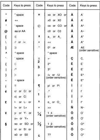
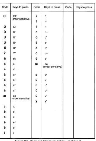
2.6 Compose Character Tables
The GraphOn 14 supports "compose sequences" as a means of generating characters that are not directly supported by the keyboard. In general, compose sequences generate 8-bit displayable characters which belong to the DEC Supplemental Graphics character set.
Compose sequences are supported only in VT220 emulation.
A compose sequence is performed by pressing the Compose Character key (labeled "Comp Char"), then pressing two keys whose characters form a valid compose sequence. No code is transmitted to the host until the full compose sequence has been entered.
Table note: To generate the indicated code, press the Compose Character key, followed by the two keys indicated in the table. The order in which the keys is pressed is not significant unless otherwise noted.
Code Keys to press Code Keys to press Code Keys to press
" #
,
@ [ \ ] 1\ , {I
} -i ¢ £ ¥ §" space tt xo or XO or
A
++ xO or xo
A
, space © co or CO or
A
aa orAA
cO or coA
( ( i! a_ orA_
A
II or 1< « «
A
)) 0 0/\
or /C.
/\ space
*
spacespace
±
+-C
2
E
(
-
2"3
E
I" 3"
)- /l- lu or IU
E
(order sensitive)
E
- space!! ~ p! or P!
1
cl or CI or /\
r
1
i
cl or
CI
1"l- or L- or Q
0_ or O_
J
1= or L= » »
N
y- or V- or
~
1 46
(order sensitive)
y= or v=
6
so or so or
~
1 20
(order sensitive)
6
s! or s! or
[image:40.470.86.413.98.554.2]sO or so L ??
0
Figure 2.2 Compose Character Tables
Table note: To generate the indicated code, press the Compose Character key, followed by the two keys indicated in the table. The order in which the keys is pressed is not significant unless otherwise noted.
Code Keys to press Code Keys to press Code Keys to press
CE
OE i i'(order sensitive)
i il\
((J 0/ ... i"
U
U'n
n-U
U'0
00
UI\6
0'0
U"0
01\V
V"6
0-B
ss0
0"it a (2 oe
a
a' (order sensitive)a
al\"
0/a
a- U ua
a" U u'a
a* 0 ul\m
ae U u"(order sensitive)
y
y"C; c,
e
ee
e'e
el\ [image:41.469.51.378.89.566.2]e
e" I i'Chapter 3
Setup
3.1 Introduction
Each installation of the GraphOn 14 places unique requirements on the terminal. Baud rate and parity must be set to match those settings in the host. Special cabling may demand the use of a non-default communications port. Other specific configuration needs may exist. To satisfy unique requirements, there must be a way to customize the terminal for use with each system.
In addition, the terminal must be alterable to suit the particular needs of software packages or the preferences of the operator.
In order to allow this customization, the GraphOn 14 is configurable by means of a Setup mode.
The terminal functions which may be altered in the Setup mode fall into three major categories.
Communications functions - these include parameters such as transmission rates and data flow control methods
System compatibility functions - these include functions such as emulation mode and how certain control codes are handled
Setup mode consists of a number of Setup screens, each of which displays the settings of logically related terminal functions. These screens are:
Directory Setup: Provides a quick way to move between the various screens.
It also supports several high level aspects of the terminal such as saving and recalling terminal parameters and resetting the terminal.
General Setup: Determines main and printer port assignments and additional
high level functions.
Devices Setup: Tells the GraphOn 14 what is attached to each of its
communications ports.
Communications Setup: Configures each of the communications ports.
Display Setup: Determines the settings of display related features such as
screen saver and status line.
Keyboard Setup: Configures the keyboard for user preferences.
Memory Setup: Displays current memory usage as well as terminal firmware
and X server revision levels.
Alpha Setup: Sets up all the functions which are unique to VT220/VT1 00
emulation.
Function Keys Setup: Defines the strings which are transmitted when a
function key is pressed. Saves and restores those definitions.
All Setup screens contain English language text, punctuated with reverse video fields. These fields indicate the items which you can select. Use the arrow keys to move the cursor up, down, right, and left from field to field. When the cursor rests on the field you wish to select, press the Enter key in the numeric keypad.
There are two basic types of fields in Setup mode. There are fields you may select to cause something to happen and there are fields you toggle in order to choose between two or more choices.
An example of a field which you toggle in order to choose one of several settings would be the first field on the second line of the General Setup screen. That field selects which communications port you will be using to exchange characters with your host computer. As you select it repeatedly by pressing the Enter key, it toggles through the choices that are available to you for use as your main port. (Most users will leave it set to Port A.)
The contents of all Setup mode fields, tab settings, answerback message, function key definitions, etc. are stored in a special memory within the terminal which continues to hold its data after the terminal has been turned off. At power-up, a working copy of this information is created. The terminal then configures itself based on the contents of this copy. When changes are made to fields in Setup mode, only the working copy of Setup memory is altered. This allows either the user or the host to make temporary changes to the terminal
configuration without affecting the permanently stored values. The DEC VT220 stores and uses Setup memory in the same manner.
Setup mode provides Save, Recall and Default functions as a means of saving these temporary settings into volatile storage, recalling settings from non-volatile storage into the working copy of memory, or setting the working copy to the factory default settings.
Function key definitions are handled the same way, but independently of the other Setup settings. This provides greater flexibility when configuring the terminal. For example, it allows you to save newly defined function keys without saving any temporary (and potentially unwanted) alphanumeric or
communications settings downloaded by the host. Separate Save, Recall, and Clear fields are located in the Function Keys Setup screen.
In conclusion:
Setup allows you to configure much of the functionality of the terminal All Setup settings and function key definitions may be saved in non-volatile memory
The terminal works with a .Q.QQ¥ of the Setup settings which are saved in non-volatile memory, so it is possible to alter settings temporarily and then recall the permanently stored settings
If a mouse or digitizing tablet is attached to the GraphOn 14, it may be used to move the cursor around the Setup screen and select Setup fields
Setup is English language in a substantially tutorial format You may give a unique name to the Setup configuration
3.2 Using Setup Mode
A Setup screen consists of a variety of fields interspersed with enough text to describe what each field does. To enter Setup mode, press the Setup key. To make a change to Setup, display the screen which holds the field you want to change, move the cursor to that field, and select it. This process works differently depending upon whether you are using a locally attached mouse. If a mouse or other input device is connected to the GraphOn 14 and the terminal is properly configured for it, simply move the cursor to the desired field and press any button on the mouse or digitizer stylus.
If no input device is attached to the GraphOn 14, or you are configuring the terminal for a new input device, press the arrow keys to move the cursor from field to field. Pressing the space bar or the Tab key is the same as pressing the right arrow. When you come to the field you wish to change, press the Enter key on the numeric keypad.
The Directory screen has several fields used for such functions as saving and recalling non-volatile Setup settings. It also displays a list of fields which provide a means of jumping directly to any of the other Setup screens. These fields provide mouse users very quick access to the remaining screens without
requiring a shift in attention from the mouse to the number keys described below. Another quick method of moving between Setup screens is to press one of the number keys above the QWERTY section of the keyboard. Once Setup mode has been entered, all screens may be accessed directly by pressing single keystrokes. The label above the QWERTY section of the keyboard indicates the screen displayed by each number key "1" through "8". Upon displaying the Alpha screen, pressing "8" again will advance you through the Alpha subscreens. To display the Function Key screen, press any function key. Not only will the Function Key screen be displayed, but the current definition for that function key will be shown. This is a very quick way to view the contents of one or more function keys.
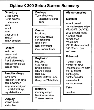
Figure 3.1 summarizes the contents of the Setup screens.
The top line of every Setup screen has three fields: Next, Directory, and Exit. Select "Next" to advance to the next Setup screen. When the last Setup screen has been reached, the Directory Setup screen will be displayed again. Press the Return key to move the cursor quickly to "Next."
Select "Directory" to move you straight to the Directory Setup screen.
OptimaX 200 Setup Screen Summary
Directory Devices Alphanumerics
Setup name Type of devices
Setup screen attached to serial
Standard
directory ports
smooth scroll save
normal/reverse video recall
Comm VT200/VT1 00/VT52
reset
baud rate wrap around mode clear comm
parity/word size new line mode default
cursor style quit X session handshaking
local echo margin bell
NUL treatment VT100 character set General max transmit rate 80/132 columns
main port soft reset
printer port
Enhanced
local/online Keyboard
7 or 8 bit controls key click monitor mode interactivityadjust auto repeat number of rows mouse factor Break disable insert/delete line attrs
DEUBS swap VT100 report
Function Keys Hold key print region
save keys Caps/Shift/No Lock print terminator recall or clear keys Compose/Meta/Hold answerback
host download enhancements
programmability of
Tabs
unshifted keys Memory
key definitions memory usage set/clear terminal revision
Display X server revision screen saver
[image:47.468.49.379.58.445.2]status line
3.3 Setup Mode Keys
When the GraphOn 14 is in Setup mode, the terminal temporarily severs the connection between the keyboard and the host computer and gives complete control of the keyboard to Setup mode. This section describes all keystrokes which have meaning in Setup mode.
Keys which take you to other Setup screens
Action
Go to Directory Setup screen 2 Go to General Setup screen 3 Go to Devices Setup screen
4 Go to Communications Setup screen
5 Go to Display Setup screen
6
Go to Keyboard Setup screen7 Go to Memory Setup screen
8 Go to Alpha Setup screen
Keys Used to Select
a
Setup Field
Up Arrow Down Arrow Left Arrow
Right Arrow
Action
Space Tab Return
Enter
same as right arrow same as right arrow
go to first field in the Setup screen - the first field is always the "Next" field which takes you to the next Setup screen
select the field the cursor points to - if it is a toggle field, the next choice will be selected; if it is an action field, the indicated function will be performed
Perform
a
Setup Function
Shift-S
Shift-R
Shift-D
Setup Short Cuts
Shift-4
Shift-5
Shift-6
Shift-O
save Setup selections into non-volatile memory if X is not active - same as clicking on "Save" in the Directory Setup screen
recall Setup selections from nonvolatile memory -same as clicking on "Recall saved VT220 configuration" in the Directory Setup screen
set the terminal to its default configuration - same as clicking on "Default" in the Directory Setup screen
toggle Local/Online - same as selecting the "Local/ Online" field in the General Setup screen
go to the next Setup screen - same as selecting the "Next" field
select the current Setup field - same as pressing Enter
3.4 Default Setup Configuration
To assist in bringing up the terminal as quickly and painlessly as possible, every terminal is shipped from the factory with each field preset to a carefully selected default value. These defaulted values give many users a terminal which will function with their system immediately.
A default GraphOn 14 is configured as follows: VT220 emulation with 24 lines of text
The main port is Port A at 9600 baud, 7 bit words, space parity, Xon/Xoff
The input device port is Port B configured for a GraphOn mouse at 1200 baud, 8 bit words, no parity, no Xon/Xoff, NULs accepted The printer port is Port C configured for a text only printer at 9600 baud,
3.5 Directory Setup
This and the following sections describe each Setup screen field by field. Refer to these sections whenever you need in-depth explanations of the fields in Setup mode.
Setup name
Directory
Save
First Line
Each Setup can be given a unique name to help make it more easily identifiable. This name can be up to ten characters long or it may be omitted completely. For example, if the terminal is configured for communicating with a 2400 baud modem, you might set its Setup name to "2400 modem."
Remember that the Setup name is just a text string - it does not necessarily reflect the current configuration of the terminal.
Second line
Select any of these fields to go directly to a different Setup screen.
Third line
To save Setup selections into non-volatile memory, click on Save. The next time you turn on the terminal, it will automatically be configured using these new settings. Function key definitions are not saved by this field. This must be done explicitly in the Function Keys Setup screen.
Recall
Reset
Clearcomm
Default
If saving is attempted during an X session, the message "Setup not saved - must exit X first" will appear on the status line.
To recall Setup selections stored in non-volatile memory, click on Recall. You might do this to restore your terminal to a known state after someone else has used your terminal or after you have finished using a software package which downloaded its own Setup configuration. This is a good way to get control of your terminal if you lose host communications during an X session.
Function key definitions are not recalled by this field. To do this, select "recall" in the Function Keys Setup screen.
Fourth line
Click on Reset to reset the terminal. This reset is similar to turning the terminal off and then on again. The last saved Setup configuration is recalled and all data on screen and in internal buffers is cleared. Function key settings are restored to the last definitions saved. The power up tests are not executed.
Click on Clear comm to reset the communications aspects of the terminal.
If your host or communications equipment causes you to lose communication in the middle of running a software package, it is possible, though rare, that the GraphOn 14 may be left in a state where it does not seem to receive characters from the host. When this happens, clicking on Clear comm may restore the terminal's ability to display these characters.
Click on Default to set all terminal parameters to their factory defaults. Function key definitions are not
Quit X session
Defaulting loads only the working copy of terminal settings - the parameters saved in non-volatile memory are not affected. To default the saved parameters, follow the default operation with a Save operation.
To exit an X session, click on this field. The X server and all clients attached to it will be aborted. The terminal will return to VT220 emulation.
This field may also be selected when the terminal is in VT220 emulation and you have reason to believe that the X server is still running. This might occur, for example, if you reset the terminal in the middle of an X session.
3.6 General Setup
The General Setup screen establishes system level functions of the terminal, including such settings as main port and printer port assignments and local or online mode.
Main port
Printer port
Local/Online
First line
Select which port is to be the main port - that is, the port which communicates with the host computer. Select which port is to be the printer port. All print requests cause data to be transmitted through this port.
Second line
7- or 8-bit controls The second field selects whether the terminal uses 7- or a-bit control codes when transmitting ANSI control sequences to the host. Most existing software
recognizes 7 -bit controls, though an increasing number of packages recognize the shorter a-bit controls as well.
Mouse factor
In general, your software will set this switch for you if it is able to use a-bit controls.
Third line
The two fields on this line allow you to adjust the
interactive feel of your GraphOn 14 in X. Instructions for using this mode are contained in Chapter 4 Using an Input Device in X. The first field contains the current setting of the mouse factor, which determines the frequency with which mouse reports are generated. The second field redefines the up and down arrow keys to adjust the mouse factor up and down interactively.
3.7 Devices Setup
This screen tells the terminal what type of device is attached to each of the serial ports. The terminal uses this information to select output drivers for locally connected printers. ·It is also used to configure the GraphOn 14 for graphic input devices such as mice.
Changes made in this Setup screen take effect upon leaving Setup mode.
First three lines
Port
Device type
Printer type
DEC printer selection
Select the port you wish to configure.
Select the type of device attached to the selected port. Valid device types are:
computer printer input device
If a port is connected directly to a host computer or indirectly through a modem, select "computer" for the port device type.
If a port is connected to a printer, select "printer," then select the type of printer. If the printer is a type not recognized by the GraphOn 14, select "text printer" -the terminal will send only displayable ASCII characters, carriage returns and line feeds. Note that this will function only in VT220/VT100 emulation, not in X. The printer types supported by the GraphOn 14 are:
text printer
DEC (LA-50/75, LN03, etc.)
ThinkJet (Epson MX/RX emulation mode) FX-80/FX-100
Okidata 92/93 FX-85/FX-185 Okidata 192/193 Okidata 84 HP LaserJet+ QMS/Talaris
Printer width
Printer width
Print termination
81W inversion
If any printer type other than text printer is selected, another field appears which selects whether narrow or wide paper is being used.
If any printer type other than text printer is selected, another field appears which selects whether narrow or wide paper is being used.
This field allows the alphanumeric print driver to determine whether to put the printer into compressed mode when printing 132 columns. If a 132 column alphanumeric display is being printed on narrow paper, the print driver puts the printer in compressed mode in order to fit 132 columns on an 8.5" wide sheet. (The LaserJet+ does not always have the right font installed to print compressed characters, so this feature is not supported on that printer.)
This field has no effect when printing a bit dump of the screen.
If a graphics printer is selected, specify whether a form feed should be transmitted after each screen dump. This print terminator applies only to bitmap dumps to a graphics printer. To select the print terminator sent at the end of a character dump from the VT220/VT1 00 emulation, go to the Alphanumeric Enhanced Functions Setup screen.
This field determines whether the bitmap data sent to the printer during a graphics dump is inverted or not. If B/W
inversion is disabled, only the "on" dots are printed. This causes white areas of the screen to print black. If B/W
inversion is enabled, only the "off" dots are printed. This yields a print in which the black areas of the screen are printed black, and the white areas are printed white. In general, you will want to leave this field set to enabled when printing X screens. You may want to disable B/W
Sixellevel
Orientation
If the printer type is set to "DEC," a field appears which specifies the resolution of the bit dump to be sent to the printer.
Sixellevel1 is used with low resolution printers with a pixel aspect ratio of 1 :2, such as the LASO. The GraphOn 14 must combine data from pairs of vertically adjacent pixels in order to print to these printers - the end result is often quite suitable, but it has half the resolution of the image on the screen.
Sixel level 2 is used with higher resolution printers such as the LN03, which support a pixel aspect ratio of 1 :1. It provides a dot for dot bit dump, generating an exact copy of the graphics bitmap.
The LA21 0 selection is similar to sixel level 2, but it selects the 1 :1.02 pixel aspect ratio supported by the LA210.
The orientation field appears only if you set the printer type to either DEC or HP LaserJet+. On these printers, this field allows you to choose how the printed image is oriented on the copy medium.
Standard orientation is also known as portrait format. The long axis of the image is oriented along the short axis of the paper. Copies fit on an 8-1/2" x 11" sheet. Rotated orientation, also called landscape format, produces a copy with the long axis of the image on the long axis of the paper. On DEC printers, rotation 90° counterclockwise results in an image which is also enlarged to a size twice that of standard orientation. The image fits on a standard page.
Expanded orientation on DEC printers produces an image in portrait format which is twice as large as a standard image. Because wide paper is necessary for the expanded image, this orientation is only useful on the wide-carriage DEC printers.
Expanded orientation on the HP LaserJet+ creates a printout in landscape format which is 50% larger than the standard size.
Input Device Protocol
Absolute/Relative
If a port is connected to a graphic input device such as a mouse, select the device protocol. The choices are:
GraphOn mouse Summagraphics mouse MM1201 tablet
If "MM1201 tablet" is selected, another field appears which asks whether to run the tablet in absolute or relative mode.
Select "absolute" mode to tie the coordinates of the tablet directly to those of the screen. For example, if you point a third of the way across the bottom edge of the tablet, the GraphOn 14 cursor will appear a third of the way across the bottom edge of the screen.
3.8 Communications Setup
This screen configures the communications of each serial port.
Changes made in this Setup screen take effect upon leaving Setup mode.
Port
Baud rate
Parity/word size
First line
The first field selects the port which will be described by all following fields in this screen.
The second field on this line sets the baud rate for the selected port. The choices are:
50 2400
75 3600
110 4800
134 7200
150 9600
300 19.2K
600 38.4K
1200 57.6K
1800
The third field sets the parity and word size for the selected port. The choices are:
Parity checking The last field turns parity checking on or off. If set to off, all characters received at the port are placed in the input buffer and processed, regardless of any transmission errors which may have been detected. The terminal gives no indication of any errors. If parity checking is turned on, characters received with any transmission errors are not displayed. Instead, a message appears on the status line for about two seconds, indicating the type of error and on which port the error occurred.
Second line
Outgoing Handshaking ...
... XONIXOFF
... DTRIDSR (and RTSon Port A only)
The first two fields indicate the type of handshaking signal or signals generated by the terminal when its input buffer is filling. XON/XOFF is supported at all ports. Hardware handshaking for flow control is supported on the DTR and RTS pins of Port A and the DSR pin of Port B. No outgoing hardware handshaking for flow control is supported at Port C.
When XON/XOFF is selected, the terminal automatically transmits XON and XOFF codes, as necessary, to control the flow of characters from the host. Select "no XON/XOFF" if XON/XOFF handshaking is not supported by the host.
If "no DTR" (or "no DSR" on Port B) is selected, DTR is manipulated exactly as if the terminal were a VT200. Select "No DTR" if DTR handshaking is not supported by the host. If it is used, DTR is used for flow control and will be lowered when the port's input buffer begins to fill. If RTS is selected, it is used for flow control in the same manner as DTR described above. RTS
handshaking is supported on Port A only.
Incoming handshaking ...
The last two fields indicate the types of incoming handshaking signals which the port will obey. XONI
... XONIXOFF
... DSRIDTR (and DSR=CD
on
Port A only)Local echo
CTS on Port A, DTR on Port B, and DSR on Port C. The "DSR=CD" setting which is available only on Port A may be used to reset the terminal when a locally attached modem drops its carrier detect line.
If the port is set to obey XON/XOFF, a received XOFF control code causes the terminal to stop transmitting characters until it receives the next XON control code. If the port is not set to obey XON/XOFF, received XON and XOFF control codes are treated as normal data characters. When XON and XOFF control codes are treated as normal data characters, they may be passed through to a device on another port, programmed into function keys, and displayed in Monitor mode in VT220/VT100 emulation. In short, they are handled as all other characters.
Select this field to require a positive hardware
handshaking signal at the appropriate pin or pins listed above. When "DSR=CD" is selected (supported on Port A only), the "DSR" pin is used to recognize the carrier detect signal from a modem. If the DSR line drops for more than one second during an X session, the terminal determines that the modem has lost connection to the host. The terminal will then reset itself and display the message: "X session disconnected by host or modem." The default Setup configuration requires incoming hardware handshaking at Port C only. The GraphOn 14 requires that a printer be attached before it will attempt to execute print commands. This default setting allows the GraphOn 14 to use a "printer ready" signal to determine if a printer is attached.
Third line
NUL Treatment
be turned off when the host echoes characters back to the terminal. If local echo is on when it should be off, you will likely see two characters displayed for every character you type. Otherwise, turn local echo on to have the terminal automatically display all characters typed at the keyboard.
Fourth line
The first field indicates whether NUL characters received at the port are to be discarded or accepted into the input buffer. Some systems use NULs as pad characters and the terminal should discard those characters.
Sometimes, however, NUL characters represent valid information which must not be ignored. For example, all input devices supported by the GraphOn 14 make extensive use of NUL characters as part of their motion reports. Obviously, these characters must be accepted into the input buffer just as all other characters.
Note that if NULs are discarded, then they cannot be passed through to a printer (or other auxiliary device) in printer controller mode and that they cannot be
displayed in Monitor mode nor downloaded as part of a function key assignment when using the GraphOn-compatible function key download sequence.
Effective transmit rate
The last field specifies the maximum effective transmit rate. The choices are:
full speed 600 baud 1200 baud 2400 baud 4800 baud 9600 baud
This field is useful if your host has trouble receiving incoming characters at high transmission rates. Character transmissions can be slowed such that the throughput to the host is the same as if the characters were transmitted at a lower baud rate. This reduced "effective transmit rate" is thus selected in terms of the equivalent baud rates listed above.
If an effective transmit rate is selected which is faster than the baud rate, characters will be transmitted as if this field were set to "full speed."
3.9 Display Setup
Two display related functions are configured in the Display Setup screen.
Screen saver
Status line
First line
This field enables screen saver. The screen saver feature, if selected, causes the terminal to darken the screen if no input is received at the terminal for 10 minutes. Any activity at the keyboard, main port, or mouse will immediately cause the terminal to restore the screen.
3.10 Keyboard Setup
All keyboard related terminal functions are configured in the Keyboard Setup screen. The only exception are the user/host definable function keys, which are supported in the Function Key Setup screen.
First line
Key click Click on the first field to toggle key click. When this
feature is on, the keyboard produces a "click" whenever a valid key stroke is accepted by the terminal. The click is not generated if the keyboard is locked or if an invalid key is pressed. Key click is the only way to get audible feedback when a key is auto repeating.
Auto repeat The next field selects whether the keys are allowed to
auto repeat. Turn auto repeat off to disable the keyboard auto repeat function. Keys will not repeat automatically no matter how long they are held down. Turn auto repeat on to have keys repeat when they have been held down for longer than one half second. Some special keys may still not repeat, depending upon the setting of the next field.
Auto repeat extent The third field determines how many keys are allowed to
auto repeat. If "all except control keys" is selected, the following keys do not auto repeat:
Setup Status Print Compose Ctrl and any key
Esc Break Return Hold