. Maintenance Guide
DSA026720
July
1989
DSA02512S (Spine). DSA02512T (Bleed Tabs). DIXGDMRS7 (Binder)
Warranties and liabilitieS
All warranties given by Intergraph Corporation about equipment or software are set forth in your' purchase contract.
The information and the software discussed in this document are subject to change without notice and should not be considered commitments by Intergraph Corporation. Intergraph Corporation assumes no responsibility for any errors that may appear in this
document.
The software discussed in this document is furnished under a license and may be used or copied only in accordance with the terms of this license.
No responsibility is a&9tiined "by Intergraph for, the' use or reliability of software on equipment that is not supplied by Intergraph or its affiliated companies. '
Trademarks
Intergraph is a registered trademark of Intergraph Corporation.
InterProt InterAct, and interView are re~red, trademarks of Intergraph Corporation.
CLIPPER. and CLIX are trademarks of Intergraph Corporation.
Other brands and product names are trademarks of their respective owners.
Classifications
Copyright
@ 1989 INTERGRAPH CORPORATION
INCLUDING THIS DOCUMENTATION AND ANY SOFfWARE AND ITS FILE FORMATS AND AUDIO-VISUAL DISPLAYS DESCRIBED HEREIN; .ALL RIGHTS RESERVED; CONTAINS CONFIDENTIAL AND PROPRIETARY INFORMATION OF INTERGRAPH AND/OR OTHER THIRD PARTIES WHICH IS PROTECTED BY COPYRIGHT, TRADE SECRET AND TRADEMARK LAW AND MAY NOT BE PROVIDED OR OTHERWISE MADE AVAILABLE WITHOUT PRIOR WRITTEN AUTHORIZATION.
RESTRICfED RIGHTS LEGENDS
Use, duplication, or disclosure by the United States Government is subject to restrictions as set forth in subdivision (cX1Xii) of the rights in technical data and computer software clause at 52.227-7013.
Unpublished-rights reserved under the Copyright Laws of the United States. Intergraph Corporation
This guide provides general setup instructions for Intergraph® workstations and servers. It consists of the following chapters:
o
Adjusting the Hardwareo
Identifying Main Components and Portso Configuring for Peripheral Devices
o Using the R5-232 Splitter Cable o Maintaining the Hardware
o Glossary of Hardware Components
Chapter 1, Adjusting the Hardware, explains procedures for setting up and adjusting monitors, keyboards, twelve-button cursors, floating menu tablets, digitizing tables, and boom assembly units. This chapter is divided into sections by monitor type. Each section contains setup and adjustment procedures for workstations with that monitor type.
Chapter 2, Identifying Main Components and Ports, includes illustrations displaying main components and ports for each type of electronics cabinet and also for InterAct and InterView workstations. Each section contains a different mechanical configuration. Chapter 3, Configuring for Peripheral Devices, discusses the peripheral devices that can be connected to the R5-232, RS-449, SCSI, or plotter port of an Intergraph workstation or server. It also includes information for connecting, configuring, and using Intergraph peripheral devices.
Chapter 4, Using the RS-232 Splitter Cable, describes the R5-232 splitter cable and its auxiliary ports, how to connect the cable to a workstation or processor, and how to configure the ports for the workstation or processor.
Chapter 5, Maintaining the Hardware, presents procedures for maintaining the workstation, main unit, keyboard, mouse and twelve-button cursor, hard disk drive, floppy disk drive and floppy disks, and cartridge tape drive and cartridge tapes.
Document Conventions
The following conventions and symbols appear in this guide:
• Workstation applies to InterPro, InterAct, and interView workstations, Intergraph's CiOO or C300 CLIPPER workstations.
• Server refers to the InterServe processors, Intergraph's CiOO or C300 CLIPPER processors.
• Workstation/server is used when the procedure or information applies to all
Intergraph workstations and servers covered.
Reference bars are provided on this page and at the beginning of each section to aid in locating a particular section. To use the bars, find the section listing on this page. Look at the edge of the document, find the corresponding bar, and open the document to that page.
DSA02512T
•
Chapter 1: Adjusting the Hardware
•
Chapter 2: Identifying Main Components and Ports •
Chapter 3: Configuring for Peripheral Devices •
Chapter 4: Using the RS232 Splitter Cable •
Chapter 5: Maintaining Your Hardware •
Chapter 6: Glossary of Hardware Components •
Chapter 1: Adjusting the Hardware 1.1 1.1.1 1.1.2 1.2 1.2.1 1.2.2 1.3 1.3.1 1.3.2 1.3.3 1.3.4 1.3.5 1.4 1.4.1 1.4.2 1.4.3 1.4.4 1.4.5 1.4.6
Workstations with 15/19-Inch Single Monitors Monitor Setup
Keyboard Setup
Workstations with 27-InchSingle Monitors
Monitor Setup .
Keyboard Setup
InterAct Workstation Dual Monitors Monitor Setup
Keyboard Setup
Twelve-Button Cursor Setup Floating :Menu Tablet Setup Digitizing Table Setup
InterView Workstation Dual Monitors Monitor Setup
Keyboard Setup
Twelve-Button Cursor Setup Floating Menu Setup
Boom Assembly Setup Digitizing Table Setup
Chapter 2: Identifying Main Components and Ports 2.1 2.2 2.3 2.4 2.5
2.6
Cube Configuration Suitcase Configuration Lowboy Configuration Two-Bay Configuration InterAct Workstations InterView Workstations
Chapter 3: Configuring for Peripheral Devices 3.1 3.2 3.2.1 3.2.2 3.2.3 3.2.4 3.2.5
Plotter Port
R5-232 and R5-449 Ports R5-232 Ports
R5-449 Ports
R5-232-Compatible Devices
Using the R5-232 and RS-449 Ports Auxiliary Port Features
Default Parameters for Auxiliary Ports
Setting Configuration for InterServe Alphanumeric Terminals Configuring the Terminal
3.2.6
3.2.7
3.3,
Configuring the RS-232 Port for the Terminal
Configuring the Workstation or Server for RS-232 Devices Configuring the Server
Using a Workstation as ,a Console Device Connecting a Host Computer
Configuring the Workstation
Using the Create Ter11li1ta1 Menu to Access a Host Computer Using the vterm Command to Access a Host Computer SCSI Port
Chapter 4: Using the R8-232 Splitter Cable
4.1
4.2,
4.3
4.445
4.5.1
4.5.2
"The RS-232 Splitter Cable RS-232 Auxiliary Ports
Accessing RS-232 Ports from UNIX and Pc-OOS Environments Connecting the RS-232 Splitter Cable
Configuring the RS-232 Auxiliary Ports InterPro Workstations
InterServe Processors
Chapter S: Maintaining the Hardware
5.1
5.25.3
5.3.1 5~3.2 5.3.35.3.4
5.3.5
5.3.6
Precautions and PreY;yA~iverMainten~nce Important Safeguards . . . . Maintaining the Workstation
Maintaining the Main Unit Maintaining the Keyboard
Maintaining the Mou..c;;e and Twelve-Button Cursor Maintaining the Hard Disk Drive
Maintaining the Floppy Disk Drive and Floppy Disks Maintaining the Cartridge Tape Drive and Cartridge Tapes
Chapter 6: Glossary of Hardware Components 6.1
6.2
6.3
6.46.5
6.66.7
6.8
6.9
6.101600/6250 Tape Drive
80011600/3200/6250 Tape Drive
Alphanumeric Terminal
Application-Specific Acceleration Processor Boom Assembly
Cartridge Tape Drive CDROM Drive
CLIPP~R ,,Processor, " DigitiZer PrOcessor Board
DigitizerlHardcopy (Plotter) Processor Board
6.11 Digitizing Table 6-5
6.12 Floating Menu Tablet 6-5
6.13 Floppy Disk Drive 6-6
6.14 Graphics Engines 6-6
6.14.1 GS 6-6
6.14.2 GX 6-6
6.14.3 GZ 6-7
6.15 Hard Disk Drives 6-7
6.16 110 Processor Board 6-8
6.17 Keyboard 6-8
6.18 Monitor 6-8
6.19 Mouse 6-9
6.20 Optical Disk Drive 6-9
6.21 Optical Disk Jukebox 6-9
6.22 Pipe Starter Board 6-9
6.23 Plotter Interface Board 6-10
6.24 Twelve-Button Cursor 6-10
List
of
Figures
1-1 15/19-Inch Monitor 1-5
1-2 15/19-Inch Monitor Ports 1-5
1-3 27-Inch Monitor Ports 1-8
1-4 27-Inch Monitor Control Panel 1-9
1-5 Color Purity Correction Knob Settings 1-10
1-6 InterAct Workstation Dual Monitors 1-13
1-7 InterView Workstation Dual M()nitors 1-17
2-1 Cube Electronics Cabinet Main Components ' 2-3
2-2 Cube Electronics Cabinet ,Ports 2-3
2-3 Suitcase Electronics Cabinet Main Components 2-4
2-4 Suitcase Electronics Cabinet Ports 2-4
2-5 Lowboy Electronics Cabinet Main Components 2-5
2-6 Lowboy Electronics Cabinet Ports 2-5
2-7 Two-Bay Electronics Cabinet Main Components 2-6
2-8 Two-Bay Electronics Cabinet Ports 2-6
2-9 InterAct Main Components 2-7
2-10 InterAct Ports 2-8
2-11 InterView Main Components 2-9
2-12 InterView Ports 2-10
4-1 The R5-232 Splitter Cable 4-3
List
of
Tables
1-1 Monitor Types 1-3
1-2 Workstation/Server Capabilities 1-4
1-3 Color Purity Correction Knob 1-11
BUSINESS REPLY MAIL
FIRST CLASS PERMIT 10. 9079 HUITSVILLE, AUIAMAPOSTAGE WILL BE PAID BY THE ADDRESSEE
Intergrapb Corporation
One Madison Industrial Park
Huntsville, AL 35807-9985
ATTN:
Manager, Systems/Workstatlons.Documentatton
Stop
CRIIOO
NECESSARY IF MAILED
We want you to critique this luanual to help us iIuprove our docluuentation at
Intergraph. After you have used this document, please answer the following
questions. Include any other comrnents you have and return the questionnaire
to Intergraph. Postage is prepaid.
Document No.:
DSA025120Document Name: CLIPPER Hardware Setup and Maintenance Guide
1
What changes would you like us to make in this doculllent?
2 .
Was the dociunent well organized? Could you find needed infornlation?
, ,j," <' '~,: "
3
Li8t any errors and the'page numbers on
.wh~chthe errors occur:
4
List specific areas you found helpful:. '
5
List specific areas you found inadequate:
6
How can we 'improve this document?
Name _ _ _ _ _ _ _ _ _ _ _
Date _ _ _ _ _ _
Telephone _ _ _ _
- __
o
rganizatiol1 _____________________________________________________ _
Address
---City _ _ _ _ _ _ _ _ _ _
_
State
ZIP
This chapter explains procedures for setting up and adjusting monitors, keyboards, twelve-button cursors, floating menu tablets, digitizing tables, and boom assembly units. It is divided into sections by monitor type. Each section contains setup and adjustment procedures for workstations with that monitor type. Table 1-1 refers you to the subsection that contains setup and adjustment procedures for your workstation type . . This chapter contains the following sections:
1.1 1.1.1 1.1.2 1.2 1.2.1 1.2.2 1.3 1.3.1 1.3.2 1.3.3 1.3.4 1.3.5
Workstations with 15/19-Inch Single Monitors Monitor Setup
Adjusting the Monitor Angle Adjusting the Screen Brightness Degaussing the Screen
Adjusting the CRT Bias Keyboard Setup
Attaching the Keyboard Adjusting the Keyboard Angle
Workstations with 27-Inch Single Monitors Monitor Setup
Adjusting the Monitor Angle Adjusting the Screen Brightness Degaussing the Screen
Adjusting the CRT Bias Adjusting the Color Purity Changing the Voltage Setting Keyboard Setup
Attaching the Keyboard Adjusting the Keyboard Angle InterAct Workstation Dual Monitors Monitor Setup
Adjusting the Monitor Head Angle Adjusting the Screen Brightness Degaussing the Screens
Adjusting the CRT Bias Keyboard Setup
Attaching the Keyboard Adjusting the Keyboard Angle Twelve-Button Cursor Setup Floating Menu Tablet Setup Digitizing Table Setup
Adjusting the Digitizing Table Height Adjusting the Digitizing Table Angle
1.4 1.4.1 1.4.2 1.4.3 1.4.4 1.4.5 1.4.6
InterView Workstation Dual Monitors Monitor Setup
Adjusting the Monitor Angle Adjusting the Screen Brightness Degaussing the Screens
Adjusting the CRT Bias Keyboard Setup
Attaching the Keyboard Adjusting. the Keyboard Angle Twelve-Button Cursor Setup Floating Menu Setup . Boom Assembly SetuP. Digitizing Table Setup
Attaching the Digitizing Table
Adjusting the Digitizing Table Height Adjusting the Digitizing Table Angle
This chapter explains procedures for setting up and adjusting monitors, keyboards, twelve-button cursors, floating menu tablets, digitizing tables, and boom assembly units. This chapter is organized into subsections by monitor type. Each section contains setup and adjustment procedures for workstations with a spe.cific monitor type.
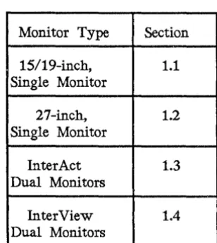
The following chart displays the section that contains setup and adjustment procedures for each monitor type (procedures are different for each monitor type). Use this chart to determine the section to refer to for sP,tup and adjustment procedures for your workstation.
Table 1-1. Monitor Types
Monitor Type Section
15/19-inch, 1.1
Single Monitor
27-inch, 1.2
Single Monitor
InterAct 1.3
Dual Monitors
InterView 1.4
Dual Monitors
Note:
[image:25.617.207.361.346.518.2]Model MIPS Main Hard Disk Graphics Monitor Main 110 ASAP VME Mechanical Configuration ~ ~. ~ c-,..
Memory Engine #-Size_ Proc Proc ~.
Oq
IP125 4
6/12
MB 156 MB GS1-15/19"
C100 80186 No No Cube~
IS200 5
8/16
MB 156 MBN/A
N/A
C100 80186N/A Yes
CubeIA220 5
8/16
MB 156 MB GS 2-19" Cl00 80186 No No Attached Digitizing Table IV220 58/16
MB 156 MB GS 2-19" C100 80186 No No Detached Digitizing TableIP225 5 16 MB 156 MB GS 1-19" C100 80186 No
Yes
CubeIS300 5 16 MB 156 MB
N/A
N/A
C100 80386N/A Yes
Suitcasei
"'t~
~
... ~
I ~
~
IS305 5 16 MB 355 MB
N/A
N/A
C100 80386N/A Yes
LowboyIP340 5
8/16
MB 156 MB GX 1-19" Cl00 80386 NoYes
SuitcaseIA340 5
8/16
MB 156 MB GX 2-19" C100 80386 NoYes
Attached Digitizing Table IV340 58/16
MB 156 MB GX 2-19" C100 80386 NoYes
Detached Digitizing TableIS3005 10 16 MB 670 MB
N/A
N/A
C300 80386N/A Yes
LowboyIP3050 10 16 MB
3551670
MB GZ 1-19" C300 80386 NoYes
SuitcaseIA3050 10 16 MB
3551670
MB GZ 2-19" C300 80386 NoYes
Attached Digitizing Table IV3050 10 16 MB3551670
MB GZ 2-19" C300 80386Yes
Yes
Detached Digitizing Table~
"'tfr
~
S·
;::t ... ~~
IP3055 10 16 MB 670 MB GZ 1-19" C300 80386 No
Yes
LowboyIP3070 10 16 MB
3551670
MB GX 1-27" C300 80386 NoYes
SuitcaseIP3075 10 16 MB 670 MB GX 1-27" C300 80386 No
Yes
Lowboy1S4000 10 16 MB 584MB
N/A
N/A
C300 80386N/A Yes
Two-BayI i
~
I
c-,...~
i
IF = InterPro workstation MIPS = Million Instructions Per Second GS = Graphics Standard
I
1.1
Workstations with 15/19-Inch
Single
Monitors
This section describes setup procedures for workstations with 15- or 19-inch, single monitors. The procedures include setting up the monitor and the keyboard. Refer to the following 15/19-inch monitor illustrations throughout this section as needed.
Monitor
I
[image:27.617.291.371.271.395.2] [image:27.617.269.396.474.639.2]Keyboard Mouse
Figure 1-1. 15119-Inch Monitor
CRT Bias
o
Degaussg
1.1.1 Monitor Setup
To set up a 15/19-inch monitor, adjust the monitor angle, screen brightness, and CRT bias and degauss the screen.
Adjusting the Monitor Angle
The 15/19-inch single monitor pivots on a rolling ball attached to the base. The monitor can be adjusted horizontally plus or minus 160 degrees and vertically plus or minus 10 degrees. Grasp the monitor and adjust it to a comfortable position.
Adjusting the Screen Brightness
Increase the brightness of the screen display by holding down the <Ctrl> key while tapping the l' key. Decrease the brightness by holding down the <Ctrl> key while tapping the'" key. The l' and", keys are on the lower right side of the keyboard.
Note:
The monitor should be on for 20 to 30 minutes before you adjust the screen.
Degaussing the Screen
The 15/19-inch single screen builds up a stray magnetic field over time or after moving the unit, causing the display to be discolored. To restore the display, press and hold the black degauss button located on the back of the monitor for five to seven seconds. If you think it is necessary to degauss the screen again, wait at least three to five minutes before a second degaussing.
Adjusting the CRT Bias
The CRT bias controls the background brightness and screen color intensity. If
necessary, adjust the CRT bias to a level appropriate for the lighting in your work area. Follow these steps to adjust the CRT bias:
1. Find the CRT bias knob on the back of the monitor above the degauss button.
2. Turn the knob all the way to the right so that lines are clearly visible on the screen.
1.1.2 Keyboard Setup
To set up the keyboard, attach the keyboard to the monitor and adjust the keyboard angle.
Attaching the Keyboard
The keyboard attaches to the keyboard outlet on the front of the base. To attach the keyboard, push the keyboard plug in the outlet until it snaps in
place.
Adjusting the Keyboard Angle
1.2
Workstations with 27-Inch Single Monitors
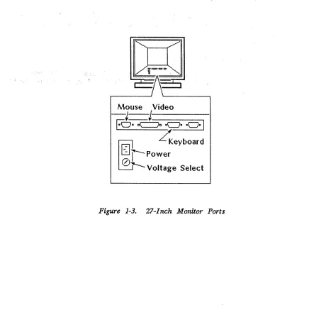
This section describes setup and adjustment procedures for workstations with 27-inch single monitors. The procedures· include setting up the monitor and keyboard. Refer to the following 27-inch monitor illustration throughout this section as needed.
CQJ
, a "r:::::::=j \;
If",'ouse
Video
-J-J
EOa a~D aCJa aeJa I
~ ~eYbOard
-,Power
0
[image:30.612.99.535.237.698.2]"1'---
Voltage Select
1.2.1 Monitor Setup
To set up a 27-inch monitor, adjust the monitor angle, screen brightness, CRT bias, and color purity and degauss the screen.
Find the control panel on the right side of the monitor head. You will use the power switch on this panel (and the power switch on the base) to power up the workstation. Then, you will use the other switches on this panel to make the screen adjustments discussed in this chapter.
1llllilllllllmllll~
-
Power Switcht!!!!!111!1!11!B11-
Degauss Button@
I~[image:31.623.118.445.288.484.2]
-0-'1' • - CRT Bias Knob
Figure 1-4. 27-Inch Monitor Control Panel
Adjusting the Monitor Angle
You can adjust the monitor horizontally by 60 degrees in both directions. Vertically, you can adjust it 3 degrees forward and 5 degrees backward. Grasp the monitor and adjust it to a comfortable position.
Note:
The monitor should be on for 20 to 30 minutes before you adjust the screen.
Adjusting the Screen Brightness
Degaussing the Screen
The InterPro workstation screen builds up a stray magnetic field over time or after moving the unit, causing the display to be discolored. To restore the display, press and hold the degauss button for seven to ten seconds. If you think. it is necessary to degauss the screen again, you should wait at least three to five minutes before a second degaussing.
Adjusting the CKI' Bias
The CRT bias controls the background brightness and screen color intensity. If
necessary, adjust the CRT bias to a level appropriate for the lighting in your work area. Follow these steps to adjust the CRT bias:
1. Find the CRT bias knob on the control panel.
2. Turn the CRT bias knob clockwise as far as it will go so that retrace lines are clearly visible on the screen.
3. Turn the knob slowly counterclockwise and stop when the lines disappear.
Adjusting the Color Purity
The electron beam that travels from the back of the monitor to the screen can
be displaced by the earth's magnetic fields before it reaches the screen. This
displacement causes discoloration on the screen. The Color Purity Correction knob allows you to correct this discoloration.
full-in t en s i ty
~
\\
Neutral/Off
~.
/ \QlliV
~/j
full-intensity
Determining the Color Purity Correction knob setting depends on these two factors:
• Which hemisphere you are in (Northern or Southern)
• Which direction your workstation faces (North or South, East, or West)
If your workstation is facing East or West, tum the knob to the Neutral/Off position regardless of which hemisphere you are in.
If your workstation is facing North or South, use the following chart to determine which direction to turn the Color Purity Correction knob.
Hemisphere you are in
Northern Northern Southern Southern
Table 1-3. Color Purity Correction Knob
Direction workstation is facing
North (away from equator) South (toward equator) North (toward equator) South (away from equator)
Turn knob
Clockwise Counterclockwise Counterclockwise Clockwise
You will notice that you can move the knob to two specific positions in either direction. These positions determine intensity. The positions farthest from the Neutral/Off position are full-intensity settings.
Changing the Voltage Setting
Your 27-inch monitor will come factory-set to the appropriate voltage for your site according to your purchase order. If you ever need to change your voltage settiIlg, contact Intergraph Field Service to make the necessary adjustments and fuse replacements on the monitor and electronics cabinet.
Caution:
Do not attempt to change your workstation's voltage setting. You could cause serious .damage to your workstation if you perform the procedure improperly.
1.2.2 Keyboard Setup
To set up the keyboard, attach it to the monitor and adjust its angle.
Attaching the ... Keyboard
The keyboard attaches to the keyboard outlet at the back of the monitor. To attach the keyboard, connect the keyboard cable to the keyboard outlet.
Adjusting the Keyboard Angle
1.3
InterAct Workstation Dual Monitors
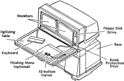
This section describes setup and adjustment procedures for InterAct workstations. The procedures include setting up the monitors, keyboard, 12-button cursor, floating menu, and digitizing table. Refer to the following InterAct workstation illustration as needed.
Digitizing Table
1.3.1 Monitor Setup
Monitors
12-button Cursor
[image:35.615.175.437.254.424.2]Base
Figure 1-6. InterAct Workstation Dual Monitors
To set up InterAct dual monitors, adjust the monitor head angle, screen brightness, and CRT bias and degauss the screens.
Adjusting the Monitor Head Angle
The monitor head pivots on a hinge under the front edge of the monitors. This
hinge allows you to adjust the monitor head forward or backward 15 degrees (3O-degree range). Follow these steps to adjust the monitor head angle: 1. Press the unlock switch on the adjustment panel on the digitizing table's
2. Press the left arrowhead to tilt the monitor head toward you. Press the right arrowhead to tilt it away from you. When the monitor head angle is adjusted to the position you want, release the adjustment switch.
3. Select the lock switch to lock the monitor head angle in place.
Adjusting the Screen Brightness
Increase the brightness of the screen display by holding down the <Ctr1> key while tapping the t key. Decrease the brightness by holding down the <Ctr1> key while tapping the'" key. The t and '" keys are on the lower right side of the keyboard.
Note:
The monitor should be on for 20 to 30 minutes before you adjust the screen.
Degaussing the Screens
The workstation screen builds up a stray magnetic field over time or after moving the unit, causing the display to be discolored. To restore the display, open the knob protection door on the front right corner of the monitor head and press and hold the degauss button for five to seven seconds. If you think it is necessary to degauss the screen again, wait at least three to five minutes before a second degaussing.
If your terminal is not equipped with a degauss button, the screens automatically degauss during the power-up procedure.
Adjusting the CRT Bias
The CRT bias controls the background brightness and screen color intensity. Adjust the CRT bias to a level appropriate for the lighting in your work area when necessary. Follow these steps to adjust the CRT bias:
1. Find the two knobs behind the knob protection door on the front right corner of the monitor head. The right knob controls the CRT bias for the right screen and the left knob is for the left screen.
3. Slowly tum the knob counterclockwise until the lines are no longer visible and the black portions of the screen become a deep black.
4. Repeat the procedure for the left screen.
1.3.2 Keyboard Setup
To set up the keyboard, attach the keyboard to the monitor head and adjust the keyboard angle.
Attaching the Keyboard
The keyboard attaches to the lower left comer of the monitor head. To attach the keyboard, locate the keyboard outlet and push the keyboard plug in the outlet until it snaps in place.
Adjusting the Keyboard Angle
The keyboard can be adjusted to four positions. To adjust, lift the levers on the back of the keyboard until the feet drop to the desired angle. Release the levers to lock the feet in place.
1.3.3 Twelve-Button Cursor Setup
The InterAct hand-held cursor is also called the 12-button cursor. The cursor attaches to the center of the digitizing table's right edge in the outlet above the adjustment panel. Push the 12-button cursor plug in this outlet until it snaps in place.
1.3.4 Floating Menu Tablet Setup
The optional floating menu attaches to the right side of the monitor head. Plug the floating menu in the outlet until it snaps in place.
1.3.5 Digitizing Table Setup
Adjusting the Digitizing Table Height
The digitizing table can be raiSed or lowered to set its height 27 to 40 inches above the floor. Follow these steps to adjust the digitizing table's height:
1. Press the unlock switch on the adjustment panel.
2. Press the up arrow on the digitizing table's height adjustment switch to increase the table height or the down arrow to decrease it.
3. Press the lock switch to lock the table in place.
Adjusting the Digitizing Table Angle
The digitizing table angle can be adjusted downward from a horizontal position up to 35 degrees. Follow these steps to adjust the digitizing table angle: 1. Grasp the front right corner of the table and lift the table angle lever on
the underside of the digitizing table. Caution:
Do not allow the table to drop.
2. RaiSe or lower the table to the desired angle.
1.4
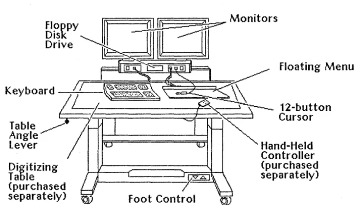
InterView Workstation Dual Monitors
This section describes setup and adjustment procedures for InterView workstations. The procedures include setting up the monitors, keyboard, 12-button cursor,
floating menu, and boom assembly. Refer to the following InterView workstation illustration as needed.
floppy Disk Drive
===~ ~=::::::~:!.-:._ Monitors
Floating Menu
K b d
1T~~""?~"&Si~""'~~~~'" ~~~~~k/.K
ey
oar4
/ ,
""~~
12-button~~l~fe ~
7n::;=:;:=:========::;;:;jl!=:;::;:-~::::'==~:::::j
Cursorlever Hand-Held
Controller
Digitizing (purchased
Table separately)
(purchased
separately) ~
Figure 1-7. InterView Workstation Dual Monitors
1.4.1 Monitor Setup
To set up the monitors, adjust the monitor angle, screen brightnes9, and CRT bias and degauss the screens.
Adjusting the Monitor Angle
[image:39.618.145.514.265.475.2]The boom assembly and monitors can be raised or lowered with the hand-held controller. An up/down switch on the boom assembly's left, front side also raises and lowers the boom assembly. However, Intergraph recommends using the hand-held controller, designed for comfort and easy use.
Adjusting the Screen Brightness
Increase the brightness of the screen displays by holding down the <Ctr1> key while tapping the t key. Decrease the brightness by holding down the <Ctr1> key while tapping the'" key. The t and .... keys are on the lower right side of the keyboard.
Note:
The monitor should be on for 20 to 30 minutes before you adjust the screen.
Degaussing the Screens
The workstation screen builds up a stray magnetic field over time or after moving the unit, causing the displays to be discolored. To restore the displays, press and hold the degauss buttons on the back of each monitor for five to seven seconds. If you think. it is necessary to degauss the screen again, wait at least three to five minutes before a second degaussing.
Adjusting the CKI' Bias
The CRT bias controls the background brightness and screen color intensity. If
necessary, adjust the CRT bias to a level appropriate for the lighting in your work area. Follow these steps to adjust the CRT bias:
1. Find the CRT bias knobs on the back of each monitor above the degauss button.
2. Tum the knob all the way to the right so that lines are clearly visible on the screen.
1.4.2 Keyboard Setup
To set up the keyboard, c attach the keyboard to the front panel of the boom
assembly and adjust the keyboard.
Attaching the Keyboard
The keyboard attaches to the front panel of the boom assembly (the front left outlet next to the up/down switch). Push the keyboard plug in the outlet until it snaps in place.
Adjusting the Keyboard Angle
The keyboard can be adjusted to four positions. To adjust, lift the levers on the back of the keyboard until the feet drop to the desired angle. Release the lever to lock the feet in place.
1.4.3 Twelve-Button Cursor Setup
The InterView hand-held cursor is called a 12-button cursor. The cursor attaches to the front panel of th~ bOom assembly (the front right outlet next to the power switch). Push the cursor plug in the outlet until it snaps in place.
1.4.4 Floating Menu Setup
The floating menu attaches to the front panel of the boom assembly (the outlet to the right of the floppy disk drive). Plug the floating menu in the outlet until it snaps in place.
1.4.5 Boom Assembly Setup
The Boom Assembly is the rectangular base below the monitors. It houses the following hardware:
• Up/down switch (left front comer) and power switch (right front comer) • Three connecting ports for the keyboard, a 12-button cursor, and a floating
menu
1.4.6 Digitizing Table Setup
To set up the digitizing table, attach the digitizing table and adjust the table height and angle.
Attaching the Digitizing Table
The following three cables attach the digitizing table to the workstation base:
• Digitizing connecting cable • Power cord
• ~otor control interconnect cable
Both ends of the digitizing connecting cable are identical. They connect from the outlet on the back under the table to the outlet on the front between the boom assembly and base.
The ends of the power cord are marked with symbols for table and workstation for easy identification. Both ends of the motor control interconnect cable are identical.
The outlets for the power ,cord and motor. control interconnect cable are together at the back of the table's base. Both cords connect from these outlets on the table to the .. outlets in the lower front right .. comer of' the workstation base.
Adjusting the Digitizing Table Height
To raise or lower the digitizing table, press the up or down buttons above the table icon on th~ hand-held controller.
Adjusting the Digitizing Table Angle
Follow these steps to adjust the digitizing table angle:
1. Grasp the table angle lever knob in the table's front left comer and move it to the right to release the table.
2. Raise or lower the table to the desired angle.
Electronics cabinets house disk drives and processor boards. A workstation/server's ports are on the back of its electronics cabinet. Intergraph produces four types of electronics cabinets: cube, suitcase, lowboy, and two-bay.
InterPro workstations consist of an electronics cabinet and a monitor. InterServe processors consist of an electronics cabinet only. InterAct and InterView configurations do not include electronics cabinets. Thus, this chapter illustrates the main component and port locations for the mechanical configurations in the following sections. Refer to the section appropriate for your workstation's configuration to discover the locations of ports and various hardware components.
2.1 2.2 2.3
2.4
2.5
2.6
Cube Configuration Suitcase Configuration Lowboy Configuration Two-Bay Configuration InterAct Workstations InterView Workstations
2-3 2-4 2-5
2-6
2.1
Cube Configuration
~:~t
!II
@'§~~
Ii
~
-I~
[image:49.623.248.394.194.288.2] [image:49.623.229.440.363.645.2]L:::::::==:=:::-:~
Compact Electronics CabinetFigure 2-1. Cube Electronics Cabinet Maln Components
o
Plotter Port SCSI Port
0000
~
~
@Q1
@r===\==-,@
C~
[QQ]@
@@C\~l![j\J]r==D
l
RS232 IEEE 802.3Mouse Port Interface Port
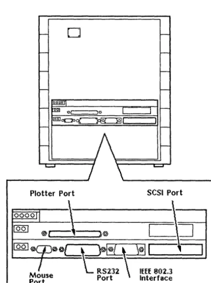
2.2
Suitcase Configuration
~ Deskside
, Electronics
[image:50.612.109.539.110.355.2] [image:50.612.188.385.389.688.2]Cabinet
Figure 2-3. Suitcase Electronics Cabinet Main Components
Plotter
II
II
pO,--rt--;.~/l
O. 8~~;t~2
RS449
tJ
~
P0J--rt
-+Ht-I~
I0
0 0
~
PO PO P1 P2 ' I I ----..
IEEE 802.3
SCSI!
I
Interface Port'-' _~~I E::=:Jo oc:::Jo
DOD
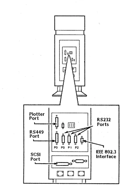
2.3
Lowboy Configuration
Note:
-~---i1--19· Electronics
Cabinet (30" high)
Floppy Disk Drive
CDROM Drive
[image:51.618.108.546.43.689.2] [image:51.618.233.470.429.589.2]Cartridge Tape Drive
Figure 2-5. Lowboy Electronics Cabinet Main Components
12-Button Cursor
Figure 2-6. Lowboy Electronics Cabinet Ports
Floating Menu Tablet
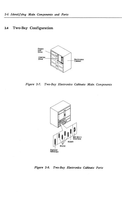
2.4
Two-Bay Configuration
Floppy DisK Drive
[image:52.613.90.517.61.760.2]Electronics Cabinet
Figure 2-7. Two-Bay Electronics Cabinets Main Components
Digitizer Hardcopy
RS232
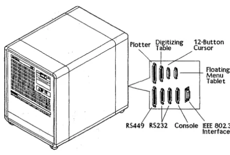
2.5
InterAct Workstations
Digitizing Table
Monitors
12-button Cursor
[image:53.620.97.519.112.714.2]8ase
The ports on the interAct workstations are behind the removable panel on the right side of the workstation base.
Follow these steps to access the ports:
1. Remove the right side panel of the InterAct workstation by loosening the retainer screw under the ledge. Lift the panel out of the slot.
2. Connect the cable(s) from the peripheral device(s) to the appropriate port(s) as shown below.
3. Replace the side panel. The cables extend through an opening on the bottom of this panel's base assembly.
Figure 2-10. InterAct Ports
[image:54.615.148.435.313.516.2]2.6
InterView Workstations
floating rv\enu
12-button Cursor
[image:55.626.151.501.219.424.2]Hand-Held Controller (purchased separately)
The ports on the InterView workstations are behind the removable panel on the left side of the workstation base.
Follow these steps to access the ports:
1. Remove the left side panel of the InterView workstation by loosening the retainer screw under the ledge. Lift the panel out of the slot.
2. Connect the cable(s) from the peripheral device(s) to the appropriate port(s) as shown below.
3. Replace the side panel. The cables extend through an opening near the floor on the bottom of this paners base assembly.
IEEE 802.3
Interface Plotter
RS232
Idev/ttyOO RS232
[image:56.613.140.529.207.569.2]Idev/tty01
This chapter discusses the peripheral devices that can be connected to the RS-232, RS-449, SCSI, or plotter port of an Intergraph workstation or server. In most cases, the information for connecting, configuring, and using Intergraph peripheral devices is provided with the unit.
To determine the location of the peripheral ports on each workstation or server, refer to the illustrations in Chapter 2, "Identifying Main Components and Ports." This
chapter includes the following topics:
3.1 3.2 3.2.1 3.2.2 3.2.3 3.2.4 3.2.5 3.2.6 3.2.7
3.3
Plotter Port
R8-232 and R8-449 Ports R8-232 Ports
RS-449 Ports
R8-232-Compatible Devices
Using the RS-232 and RS-449 Ports Auxiliary Port Features
Default Parameters for Auxiliary Ports
Setting Configuration for InterServe Alphanumeric Terminals Configuring the Terminal
Configuring the R8-232 Port for the Terminal
Configuring the Workstation or Server for RS-232 Devices Configuring the Server
Using a Workstation as a Console Device Connecting a Host Computer
Configuring the Workstation
Using the Create Terminal Menu to Access a Host Computer Using the vterm Command to Access a Host Computer SCSI Port
3.1
Plotter Port
The plotter (V80) port can support electrostatic, laser, color thermal hardcopy, or Intergraph Film Recorder (PCR or QCR) output devices for all Intergraph
workstations and servers. You can connect Versatec-Differential devices (most Versatec Electrostatic plotters, Intergraph Film Recorders, and the Intergraph Laser Printer 811) to the workstation/server by connecting the cable that come with the device directly to the plotter port and to the appropriate port on the device. To connect TIL or Centronics devices to a workstation/server, first connect one of the following interface conversion assemblies (which comes with the
workstation/server) to the plotter port. This plotter port is an adapter to which you can then connect the device cable.
• The Differentia1lV80 conversion assembly (FINF355) is used with TIL Devices (V80 plotters or Benson Electrostatic plotters).
• The Differential/Centronics conversion assembly (FINF356) is used with Centronics devices such as the Color Thermal Hardcopy.
The Intergraph workstation and server plotter ports can support up to four output devices if they are connected to an Intergraph Plotter Multiplexer/Selector (purchased separately) to which the devices are also connected. See the Plotter Multiplexer/Selector User's Guide for directions on connecting and using the Plotter Multiplexer/Selector.
The following hardcopy devices from the Intergraph workstation/server plotter port are supported. The procedures for connecting, configuring, and using these devices are delivered with each peripheral.
• Versatec V80 Screencopier/Plotter • C5602 Color Thermal Plotter • CHC-635 Color Thermal Hardcopier • Intergraph Laser Printer 811
These are hardcopy devices for servers and CLIPPER workstations only:
•
Versatec CE 3236•
Versatec CE 3224•
Versatec CE 3244•
Versatec CE 3436•
Versatec CE 3424•
Versatec CE 3444•
Versatec 7236•
Versatec 7222•
Versatec 7224•
Versatec 7244•
Versatec 7436•
Versatec 7422•
Versatec 7424•
Versatec 7444•
Benson 9624•
Benson 9636•
Benson 96443.2
RS-232 and RS-449 Ports
All Intergraph workstations and servers feature R8-232 ports for connecting standard R8-232-compatible devices such as modems, printers, or plotters. In addition, workstations and servers with the suitcase, lowboy, or two-bay electronics cabinet configuration feature an 449 port for connecting RS-449-compatible modems, printers, or plotters.
3.2.1 RS-232 Ports
Workstations and servers with a single R8-232 connector (cube electronics cabinet configuration) can connect up to three devices to the R8-232 port with a special R8-232 splitter cable. This cable, which splits the R8-232 port into three separate RS-232 connectors, is provided with each workstation/server. You may purchase additional R8-232 splitter cables from Intergraph.InterAct and
interView workstations have two RS-232 ports that you can use, while the system reserves the third for the digitizer table.
3.2.2 RS-449 Ports
3.2.3 R5-232-Compatible Devices
The following are several RS-232-compatible devices that the RS-232 port on Intergraph workstations/servers supports and that you can purchase from Intergraph. The procedures for connecting; configuring, and using these devices are delivered with each peripheral.
• HP7570 Pen Plotter • HP74 75 Pen Plotter • HP7595 Pen Plotter • HP7596 Pen Plotter • Calcomp 1076 Pen Plotter • Calcomp 1077 Pen Plotter • CIT-224 Alphanumeric Terminal • P600 Line Printer
• DX2200 136-Column Dot Matrix Printer • DX2100 80-C0lumn Dot Matrix Printer • LA120 DECW riter ill
• Standard Asynchronous Modems
3.2.4 Using the RS-232 and R5-449 Ports
All Intergraph workstations/servers feature an R5-232 port configured to support three R5-232-compatible serial ports: auxOO, auxOl, and aux02 (auxiliary ports 0, 1, and 2). However, workstations and servers with the suitcase, lowboy, or two-bay configurations support three R5-232 ports or one R5-449 port and two RS-232 ports~'
PortO transmits and receives data, has RTS and
crs
signals, and is the only port that can generate modem control signals (RI, DTR, and DTS). That is, porto
is the' only port that can automatically terminate a remote session when you are disconnected but have not logged off from the system. Ports 1 and 2 transmit and receive data and have RTS andcrs
signals.AuxUiary Port Features
The following chart shows the features that each auxiliary port supports.
Table 3-1. Auxiliary Port Features
auxOO auxOl aux02
Is accessed from X X X
UNIX operating system
Transmits and X X X
receives data
RTS,
ers
X X XRI, DTR, DTS X
Has a digitizer X
attachment
To access the ports from the UNIX System V environment, refer to aux(7) change pages in the UNIX System V Administrator's Reference Manual.
Default Parameters for Auxiliary Ports
From the Peripheral Configuration Utility menu of the workstation/server, you can establish default parameters for each port. Intergraph set the default parameters for standard RS-232 and RS-449 devices. However, you can change these parameters to support the peripheral devices you want to attach.
[image:64.615.107.498.117.406.2]3.2.5 Setting Configuration for InterServe Alphanumeric Terminals
The following procedures describe how to configure the terminal and RS-232 port for the terminal.
Configuring the Terminal
If multiple settings are available for your alphanumeric terminal communication settings, set the terminal to the following recommended values:
Baud Rate Word Size Parity Stop Bits
Auto XONIXOFF
9600 bits 8 bits None 1
Yes (enabled)
Refer to the user documentation accompanying the terminal for directions on setting the parameters.
Configuring the RS-232 Port for the Terminal
1. Power up the InterServe and access the Startup Utility menus from the InterServe Introductory screen.
2. Configure the appropriate R8-232 port for the alphanumeric terminal according to the directions in subsection 3.2.3, "Configuring the Workstation or Server for RS-232 Devices."
If the alphanumeric terminal has fL"'I(ed values for communication settings, set the values on the Peripheral Configuration menu to match the list of values provided with the alphanumeric terminal.
Peripheral Configuration Menu AUX_select Baud_Rate Word_Size Stop_Bits Parity auto_XON/xoff incoming_XOFF auto_RTSI cts Slave_Device UTility (0) (9600) (8) (1) (Non.e) (Yes) (Yes) (Yes) (No)
[go to main utility menu]
See Chapter 8 in the CLIPPER Operator's Guide for a complete description of the InterServe Peripheral Configuration menu.
3.2.6 Configuring the Workstation or Server for RS-232 Devices
Step-by-step procedures for configuring the workstation and server for RS-232 devices follow.
Configuring the Workstation
1. Select the Utility screen button from the introductory screen.
2. Select the Peripheral Configuration screen button from the Utility Page. 3. When the Peripheral Configuration page appears, find the Aux Port Select
roll-through box.
4. If a peripheral is connected directly to the RS-232 port, leave the setting for the Aux Port Select at auxOO. If the RS-232 splitter cable is used, select the name of the R5-232 port to be configured. For dual-screen workstations, select the port setting that corresponds to the port number connected to the peripheral.
To configure ...
Auxiliary port 0 Auxiliary port 1 Auxiliary port 2
Set Aux Port to ...
5. When the name of the port to be configured displays, establish all other settings (such as baud rate, parity, and word size) for that port. These settings should be sent with the peripheral.
6. Once a port is configured, select the Save button at the bottom of the screen to save the settings for that port.
7. Select the System V screen button to load the System V operating system.
Configuring the Server
1. Power up the lnterServe and access the Startup Utility menus from the lnterServe introductory screen.
2. Key in UT at the Startup Configuration Utility introductory menu to display the Main Utility Menu.
3. Key in PS at the Main Utility Menu to display the Peripheral Configuration menu •
• If a peripheral is connected directly to the RS-232 port, key in the following to display 0 beside the AUX-se1ect option.
$ AUX 0
• If the RS-232 splitter cable is used, indicate the port connected to a device as follows. (The appropriate port number displays beside the A"DX-se1ect option.)
To configure . . .
Auxiliary port 0 Auxiliary port 1 Auxiliary port 2
Key in
4. Establish all other settings by keying in the capital letters from each option name and then keying in the setting as an argument. (A list of the settings
is included with the peripheral.) For example, key in the following to set the baud rate to 1200:
Option: BR 1200
The keyed-in settings appear beside the appropriate option. Chapter 8 in the
CLIPPER Operator's Guide explains the various settings.
5. Once the appropriate settings are established, key in SA to save the settings for the port selected in step 3.
3:2.7 Using a Workstation as a Console Device
The workstation can be connected to a host computer and used as a console device (serial line terminal). The following procedures describe how to connect, configure, and access a host computer.
Connecting a Host Computer
A host computer can be connected directly to the R5-232 port(s) on a workstation.
Configuring the Workstation
The procedures used for configuring the RS-232 port for a modem, printer, or plotter can also be used for configuring a host computer. The following illustration shows the console device settings for auxiliary port 0:
I
Configuration PeripheralScreen Screen Siver
~ Key Click. Keyboard Membrane Click
Digitizer ~~ Ben Tone
floetinl Menu Present
~ ~
Serial Port Parameters Aux Port Select
8UXOO lEj
Slave Device Port Type Auto XON/XOFF
~ ~ ~
BlUdR.te Word Size Incoming XOff
~ ~ ~
Parity Stop8its Auto R IS/CTS
~ ~ ~
~ ~ [Sy,temV) (PC-DOS)
Using the Create Terminal Menu to Access a Host Computer
You can use the following procedure to access a host computer and create a console window:
1. Select the Terminal option from the Workstation menu.
2. When the Create Terminal menu appears, select the RS-232 option. 3. Select the OK screen button to exit the menu and the console window is
automatically created. Note:
Since an auxiliary port is not specified in this procedure, the system
automatically checks for an available host to connect to. For example, if a host computer is connected to port 0 and another host computer is connected to port 1, the system checks first to determine whether port 0 is available.
If port 0 is not available, the system then checks port 1.
Using the vterm Command to Access a Host Computer
The vterm command allows you to access a host computer connected to a
specific port with one of the RS-232 splitter cables. In this example, the vterm command is keyed in from a local window on the workstation to access a host computer connected to port 1 of the splitter cable.
# vterm -aOl
3.3
SCSI Port
The SCSI port is. an industry-standard interface that allows optional devices, such as internal or external hard disk drives and tape drives, to communicate with an Intergraph workstation/server. The Intergraph External Hard Disk Drive, Single Optical Disk Drive, External Cartridge Tape Drive, and 1600/6250 bpi Tape Drive can be connected to the SCSI port on InterPro workstations and InterServe processors. The Standalone Optical Disk Drive is available for InterPro 340 workstations, 3000-series workstations/servers, and 4000-series workstations/servers only. For information on backup and restore procedures, see Chapter 5 in the
CLIPPER Operator's Guide.
The SCSI bus of InterPro workstations and InterServe processors allows many optional SCSI devices consisting of disks and tape drives to be connected in a daisy chain. The SCSI bus allows 20 feet of cable to be used to configure a system of SCSI devices. These devices will be connected to an InterPro workstation or server. See the following section for instructions to decide the feasibility of multiple SCSI devices wi~h your workstation or server.
This chapter describes the R8-232 splitter cable and its auxiliary ports. It then
explains how to connect the cable to a workstation or processor and how to configure the ports for the workstation or processor. It contains the following sections:
4.1
4.2 4.3
4.4
4.5
4.5.1
4.5.2
The RS-232 Splitter Cable R8-232 Auxiliary Ports
Accessing R8-232 Ports from UNIX. and PC-DOS Environments Connecting the R8-232 Splitter Cable
Configuring the RS-232 Auxiliary Ports InterPro Workstations
InterServe Processors
4-3
4-3
4-4
4-4
4-4
4-5
4.1
The RS-232 Splitter Cable
[image:75.620.124.460.275.459.2]Although an InterPro workstation or InterServe processor has a single RS-232 connector, up to three standard RS-232 devices can be connected to an InterPro workstation or InterServe processor RS-232 port with the RS-232 splitter cable. This cable splits the RS-232 port into three separate 2S-pin RS-232 connectors. These connectors serve as auxiliary ports to which devices such as printers, plotters, modems, and other computers can be connected.
Figure 4-1. The RS-232 Splitter Cable
4.2
RS-232 Auxiliary Ports
The RS-232 port is configured to support three R5-232-compatible serial ports: auxOO, auxOl, and aux02 for auxiliary ports 0, 1, and 2. All three auxiliary ports can be accessed from the System V UNIX. environment as Idev/ttyOO, Idev/ttyOl, and Idev/tty02.
Port 0 transmits and receives data, has RTS and
crs
signals, and is the only port that can generate modem control signals (RI, DTR, and DTS). That is, porto
is the only port that can terminate a session automatically when the user hangs up (or is accidentally cut off) or that can hang up automatically when a program is terminated.4.3
Accessing RS-232 Ports from UNIX and PC-DOS Environments
To learn how to access the ports from the System V UNIX environment, refer to aux(7) documentation in the System V Administrator Reference Manual.4.4
Connecting the RS-232 Splitter Cable
Follow these steps to connect the splitter cable to an. InterPro workstation or InterServe processor:
1. Attach the RS-232 splitter cable's main connector to the RS-232 port on the InterPro workstation or InterServe processor.
Note:
See Chapter 2, "Identifying Main Components and Ports," to learn the RS-232 port's location on your InterPro workstation or InterServe processor. 2. Connect the 25-pin cable (that comes with the RS-232 device) to the
appropriate connector on the splitter cable.
To connect to a printer, do not use the cable that comes with it. Instead, use the extra cable that comes with the RS-232 splitter cable. Attach this cable to the appropriate connector on the splitter cable.
3. Attach the RS-232 cable to the appropriate port on the RS-232 device.
4.5
Configuring the RS-232 Auxiliary Ports
4.5.1 InterPro Workstations
Follow these steps to configure the InterPro workstation RS-232 from the Utility pages:
1. Boot the workstation and select the Utility screen button from the blue introductory screen.
2. Select the Peripheral Configuration screen button on the Main Utility Page.
Workst,tionPlssword
>
Timezone Atl..,tic(C·.) ~
O.yHaht S.Vtnll
i Stondlrd
>
OIY~lht Iv ....
~
Current Time
~
Debutt Oper.tina System
I System V
>
PC-DOS IPeriphenl Confilwation ~
Operltina System P.rll'n.t." c:=:==J
Disk Maintenlne. UUNty c:=:==J
DisI< Portitionlnf UtUily c:=:==J
Device knl.e Copy Utifity c:=:==J
3. When the Peripheral Configuration Page appears, find the Port Select roll-through box.
Peripheral Configuration
Screen Screen Saver
~ Key Click Keyboard Mambr.ne Click.
Ea~
Digitizer
Bell lORe
floating Menu Present
~ ~
Serial Port Parameters
A,ux Port Seled
8U.00)l; ~ SI.ve Device Port Type Auto XONIXOFf
~ ~ ~
Baud Rate Word Size Incoming XOFf
~ ~ ~
Perity StopBih Auto R ISICTS
~ ~ ~
~ ~ (Sy,temV) (PC·DOS)
~ ClOiCl ~
4. Select the name of the RS-232 port that will be configured.
To configure . . .
Auxiliary port 0 Auxiliary port 1 Auxiliary port 2
Set the port to . . .
auxOO auxOl aux02
5. Establish all other port settings (such as baud rate, parity, and word size). The values for these settings should be provided in documentation
accompanying the peripheral device. Refer to Chapter 8 in the CLIPPER Operator's Guide for directions for setting the values of Peripheral
Configuration menu parameter fields.
6. Once all ports are configured, select the Save button at the bottom of the screen to save the settings for each port.
4.5.2 In terServe Processors
Follow these steps to configure the InterServe processor R5-232 auxiliary ports from the alphanumeric Utility menus:
1. Boot the InterServe processor and press any key when the following message appears.
Intergraph Corporation InterServe processor
Strike any key within 5 seconds to access Startup Utility Menus.
2. When the following menu appears, key in UT to display the Main Utility menu.
Startup Configuration Utility
UTility UNix Help
[go to main utility menu] [boot unix operating system]
Key in your selection at the Option prompt. Capitals indicate key-in abbreviations.
3. At the Main Utility menu, key in PS to display the Peripheral Configuration Menu.
Main Utility Menu
PassWord DAte Peripheral_Settings Operating_System Disk_Maintenance Disk_Partitioning Device_image_CoPy
Standard Options:
(inactive)
(Mon Dec 14 10-.51:01 1987) [go to peripheral config menu] [go to unix config menu] [go to disk maintenance menu] [go to disk partition menu] [go to device copy menu]
UNix SAve LOad R&et Help
Option: PS
4. At the Peripheral Configuration M~mu, key in the following to display RS-232 in the Port Type field.:
Option: rs-232
5. Select the name of the RS-232 port to be configured.
To configure . . .
Auxiliary port 0 Auxiliary port 1 Auxiliary port 2
Key in . . .
Option: AUX 0 Option: AUX 1 Option: AUX 2
6. Establish all other port settings (such as baud rate, parity, and word size). The values for these settings should be provided in documentation
accompanying the peripheral device. Refer to Chapter 8 in the CLIPPER
Operator's Guide for directions on setting Peripheral Configuration Menu field
parameters.
The following is the Peripheral Configuration ~1enu when port 1 is
configured with standard settings.
Peripheral Configuration Menu
AUX_select Port Type
Baud~ate Word_Size Stop_Bits Parity auto_XO~/xoff incoming_XOFF auto_RTS/cts Slave_Device UTility ~ix Option:
Standard Options:
SAve LOad REset
(1) (rs-232) (9600) (8) (1) (~one) (Yes) (Yes) (Yes) (~o)
[go to main utility
Help
7. Once all ports are configured, key in the following to save settings for each port:
Option: SA
8. At the next menu, key in the following to load the System V operating system.