-COGAR
SYSTE M
4®
- - -
r-PROGRAMMER'S
REFERENCE
PROGRAMMER'S REFERENCE MANUAL
This publication is designed to be used as a reference manual by programmers using the Cogar System 4® Processor. The manual is divided into three parts. Part I defines the unique features of the machine which are relative to the programmer, as well as providing a machine specification summary. Part II provides general information on the usage of each group of instructions in the instruction set repertoire. Part III defines each instruction in detail, and provides the timing and an example of how each instruction may be used in context with surrounding instructions, in both Source and Object coding. A summation of all the instructions in the repertoire is contained on the Cogar System 4 Instruction Reference Card.
Other publications relating to software for the Cogar System 4 are:
Batch Assembler Operating Instructions; which contains the step-by-step instructions for creating a self-loading program tape, which has been assembled as part of an Object-String background.
Standard Cogar Library Functions; which contains descriptions and operating instructions for the Language Base Library and the I/O Libraries.
PROGRAMMER'S REFERENCE MANUAL
Table of Contents
Page
COGAR INSTRUCTION DESCRIPTION INDEX ... c. SPECIFICATION SUMMARY ... e.
SECTION I. GENERAL
System Features . . . .. . . .. . . .. . . .. . . 1
Language F ea tures ... 1
lOS Features . . . .. .. . . .. . 2
Assembler Features... 2
D; s play . . . 3
Keyboa rd . . . 4
Cartridge Tapes ... 4
Operator Controls ... 7
SECTION II. INSTRUCTION USAGE Subroutine Control ... .... .... .. .. .. .. .. ... ... .. .. .. 8
Reg; sters ... 11
Addressing ... ','" ... 11
Symbols ...•... 13
DPL-l Instruction Classes ... : .. 14
DPL Punctuation ... 16
Literal Notations ...•... 16
Standard C4 Program Record (Mini-Tape) ... 17
Subroutine Relocatability ... 19
Tape I/O Character Queue ...•... 19
SECTION III. INSTRUCTION DESCRIPTIONS Genera 1 . . . . • . . . .. 21
Cl ass 0: Jump ...•... 22
Cl ass 1: Branch ... 26
Class 2: Transfer ... 46
Class 2: Ordinary Arithmetic ... 50
Class 3: Boolean Arithmetic ... 54
Cl ass 3: Compare ... 60
Group 1: I/O Functions ... 62
Group 2: Data Modify ... 68
Group 3: Compay"e ... 73
Group, 3: Se,' ect ... 74
Group 4: Control Functions ... 81
Notations for DPL-3B Constants ...•... 85
DPL-l Pseudo Instructions .•... 86
DPL-l Branch and I/O ... 95
Mnemonic ADA ASS ADX ANA BRE BRH BRL BRU COM CPA CPI CPX DIV DPI EJT END ENT EPI EQU ERA EXB EXU GET 1OC-C#3 IOC-C#N .. . 1OC-C#4 .. .
IRA LOA LOX LlA LPS LSW MOV MUL ORG OVL
PCL-PRT .. . PCL-TYP .. .
PUT SAC SAN SBE SBH
COGAR INSTRUCTION SET INDEX
Name Format
Add to Accumulator ... DPL-l Add Storage to Storage ... DPL-2 Add to Index Register ···DPL-l Logical 'AND' to Accumulator ... DPL-l Branch on Equal ···DPL-l Branch on High ···DPL-l Branch on Low··· DPL-l Branch Unconditional ... DPL-l Compare Storage to Storage ... DPL-2 Compare Accumulator ···DPL-l Clear Processor Interrupt ... DPL-l Compare Index Regi ster ... DPL-l Divide ... DPL-2 Disable Processor Interrupt ... DPL-l Eject to Top of Form ... DPL-l End Segment ... DPL-l Enter Control Function ... DPL-l Enab 1 e Processor Interrupt ... DPL-l Equate Symbol· .... · ... · .... · .... · DPL-l Exclusive 'OR' to Accumulator ... DPL-l Exit and Branch ... DPL-l Exit Unconditional ... DPL-l Get Data (Read) ... DPL-2 I/O Keyboard ... DPL-l I/O Mini-Tape ···DPL-l Display Control ... DPL-l Inclusive 'OR' to Accumulator ···DPL-l Load Accumulator ... DPL-l Load Index Register ... DPL-l Load Instruction Address ... DPL-l Load Processor Status ... DPL-l Load Sense Switches ···DPL-l Move Storage to Storage ... DPL-2 Multiply··· DPL-2 Origin LOcation Counter ... DPL-l Overlay ... DPL-l Line Printer Control ... DPL-2 Typewriter Control ...•.. DPL-2 Put Data (Write) ... DPL-2 Set Arithmetic Condition' ... DPL-l Shift & Logical 'AND' to Accumulator···· DPL-l Stack and Branch on Equal ... ·· .. · .... DPL-l Stack anff Branch on High ... DPL-l
Mnemonic
SBL ... . SBU .... .. SEG .... .. SEL-EQL SEL-HGH SEL-LOW SEL-NEQ SEL-NHG SEL-NLW SEL-UNC
SER ... . SET .... .. SIR· .... . SMC .... .. SMS .... .. SSC .... .. STA ... . SUA .... .. SUB .... · . SUX .... .. TCL .... .. TLJ .... .. TLX ... . TMJ .... ..
TMX ••••••
USE ...
COGAR INSTRUCTION SET INDEX
Name Format
Stack and Branch on Low··· DPL-l Stack and Branch Unconditional ... DPL-l Identify Segment ... DPL-l Selcect Equal ...•... DPL-2 Select High ... DPL-2 Select Low ... DPL-2 Select Not Equal··.·· ... DPL-2 Select Not High ... DPL-2 Select Not Low· ... DPL-2 Select Unconditional ... DPL-2 Shift and I EOR I Accumul ator ... DPL-l Set Page ... DPL-2 Shift and 'IOR ' Accumulator ... DPL-l Set Memory Control ... DPL-l Set Memory Section ... DPL-l Set Memory Section and Control ... DPL-l Store Accumu 1 a tor ... D PL-1 Subtract from Accumulator ... DPL-l Subtract Storage to Storage ... DPL-2 Subtract from Index Register ... DPL-l Tape Control Command ... DPL-2 Test Literal and Jump ... DPL-l Test Literal and Exit ... DPL-l Test Mask and Jump •... DPL-l Test Mask and Exit ...• DPL-l Use External Source Segment ... DPL-l
SPECIFICATION SUMMARY
Size
Weight
Power
Environment
Ventilation
Processor
Memory
Keyboard
Visual Display
Tape System
10 inches high (25 cm) 18.5 inches wide (47 cm) 24 inches deep (60 cm)
60 pounds (27 kg)
115 VAC ±10%, 220 VAC ±10% 48 to 62 Hz
2.5 amps average
10% to 80% relative humidity without condensation
60°F to 95°F Operating Temperature OaF to 150°F Storage Temperature
30 cubic feet per minute air flow 4 inches air flow clearance on all sides 1000 BTU per hour heat dissipation
45 instruction types plus 1/0
3 to 6 iJ.s instruction cycle time 1 Accumulator
7 Index Registers per 2K of memory 16 Member Instruction Address Stack Hardware Bootstrap Loader
16K bytes capacity
Random Access Read/Write Non-Destructive Read-Out Monolithic Semiconductor
Software configurable Hall effect keys
N-Key rollover capability Audible cue
5 inch CRT
4 or 8 line display, with interleave capability
32 characters per line
5 x 8 matrix under program control
10 ips write tape speed
1600 bpi density, phase modulation 2 mechanically independent transports Read after Write, CRC, phase checks Automatic threading
SECTION I. GENERAL
1. SYSTEM FEATURES
The Cogar System 4 is a compact, operator-oriented, general purpose data processing system. It combines, in a single unit, an input keyboard, magnetic tape transports, CRT visual display, I/O interface, solid state memory and a versatile processor. The System architecture closely in-tegrates the functioning of all sub-systems and features transparency of graphics and coding. All major system functions are under program control. The processor structure is designed to optimize byte handling and inter-pretation, and provides automatic threading of recursive subroutines.
The nature of the processor design and its relationship to the other system components make the Cogar 4 heavily dependent on software. This means that the system is uniquely flexible in the jobs it can perform and
is especially adaptable for various operator and interfact applications. It also means that software is an essential ingredient that must be as fully and carefully integrated into the System as the other components.
The Cogar 4 is a binary machine using 8-bit bytes in its memory organ-ization and most hardware data paths. Its operations are highly memory oriented and are designed to take advantage of the performance of its semiconductor storage.
2. LANGUAGE FEATURES
The language base for the Cogar System 4 is flexible, easy to learn and use, yet permits the programmer to take full advantage of the System 41s power. The Cogar Language Base is comprised of a comprehensive set of "Pre-packaged" functions to facilitate modular program construction. The Cogar Assembler provides linkage between these functions and the specialized routines necessary to a given application.
The DPL-l instructions for the Cogar 4 are machine level instructions that are directly executed while the DPL-2 commands are executed inter-pretively by a resident software monitor. DPL-l instructions are two bytes long and must occur on even byte boundaries. DPL-2 commands are four bytes long and should also occur on even boundaries. When DPL-l and DPL-2 are intermixed, a new language is formed called DPL-3. The batch assembler for DPL-3 is known as DPL-3B. A subset of the DPL-2 monitor that handl es I/O functi on is known as the I/O Supervi sor or lOS. This manual describes DPL-l and IDS as assembled on DPL-3B.
In order to be able to tailor the system for optimum use with particular applications, many device functions have been designed for program control. The codes generated by the keyboard, for example, correspond not to the
key character, but to the key location. A translate table is located in the processor memory and is used to convert a key code into a character code. The user program can easily modify the translate table and can thus produce any desired code for any key.
The visual display uses a 5 x 8 dot matrix to form each display character and has cursor control with each character. The dot matrix is stored in the processor memory so that any possible 5 x 8 combination may be
generated by the user program to be displayed for any character code. The standard dot pattern uses a 5 x 7 dot matrix to form the desired
character. This provides for a space between the character and the cursor.
The Cogar 4 provides an unusually efficient subroutine control mechanism that is easy to use, yet offers powerful capabilities.
3. IDS FEATURES
Cogar has designed an Input/Output Supervisor to provide easy access for the user to a set of standard I/O routines. The flexibility of the system peripheral device operations is still available for special applications, but most I/O operations can be accommodated by the I/O Supervisor. IDS is a memory resident software monitor that is accessed using the ENT:IOS pseudo command. It performs a complete single operation and automatically returns control to the user program.
4. ASSEMBLER FEATURES
Since the programmer spends much of his time communicating with the Assembler, it is useful to supply commands that control the operations of the Assembler itself. These commands are called Pseudo instructions and normally do not result in any Object coding. Another class of Pseudo instructions used in the Cogar 4 Assembler to control executive monitor operations does generate Object coding.
The Cogar Batch Assembler, known as DPL-3B, provides many features de-signed to streamline the programming process. Comments may be inserted in the Symbolic program to help identify the operations taking place. Instructions, data, constants and locations may all be referred to symbolically. Diagnostics are generated to help identify errors in the program. Editing, display and printing of both Object and Symbolic programs are available as part of the DPL-3B package.
The Cogar Assembler also handles the appropriate translations, controls, and linkages for the lOS and DPL-3 monitors.
5. DISPLAY
Keyboard Transparency:
The Cogar System 4 is designed to provide code hardware transparency. Any keyboard character may be automatically translated to any desired code and any dot matrix pattern may be displayed for a given character code. These functions are directly under software control and are thus available to the programmer.
Selective Blanking:
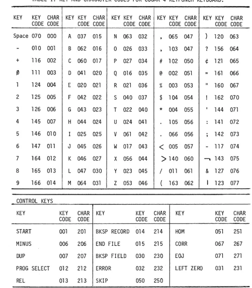
The commonly used internal key and character codes in standard Cogar software are shown in Table 1. Notice that the high order octal digit is always zero. This digit corresponds to the bits six and seven of the character byte. These two bits are used to provide added features for the CRT display. If a 1 is inserted in bit 7 (changing the code for A, for example, from 015 to 215) of a character in the CRT buffer area, that character will be displayed on the screen as a blank.
Cursor Underscore:
Selective Interlace:
Memory areas displayed are program selectable from anyone of 16 memory Pages (256 bytes per Page), with provision for half Page (128 bytes) dis-play only or for selective interlace of half-Pages.
6. KEYBOARD
When a character key is depressed on the keyboard after a Transfer Byte IOC, it causes a key code to be loaded into the accumulator. The NUM (numeric), CTRL (control) and ALPHA (alphabetic) are three special keys that act on bits 6 and 7 of the key code for any key pressed while one of them is held down. NUM turns on bit 6, CTRL turns on bit 7, and ALPHA turns on both 6 and 7. If none of the special keys are activated, bits 6 and 7 remain off. The following procedure may be used to translate the key code residing in the accumulator into a character code.
a. The 6th and 7th bits are taken care of as follows: 6th bit on: do not change
7th bit on: turn 7th bit off (reset after translation, if des ired) .
6th and 7th bits on: turn 6th and 7th bits off (reset after trans-lation, if desired).
b. Store the result in an index register
c. Add to the index register the displacement within the page of the beginning of the translate table. The standard translate table in page 05, for example, starts at location decimal 064, therefore, add decimal 064 to the value of the index register containing the key code before translation.
d. Load the Accumulator using indexed addressing and the page where the translate table resides. The Accumulator now contains the character code for the key that was depressed. The translate table may be designed by the user to supply any desired 8 bit character
code including ASCII, EBCDIC, etc. 7. CARTRIDGE TAPES
PAGE III
PAlE 83
PAGE 11'1 CRT
DDT PArT
ODD 100 20G 30D --ODD 110 2n 311 -ODD 100 210 30a --ooa liD 2" 300 ODD 100
E~ .200 300
---~ - --
-PAGE B5 TRANSuliE TAIL KEYPUNCN
ODD r==== 100 ;-- 200 ' -300 - - -000 100 200 .300 -DOD loa 20D 300 - - i - - - -
-00
• I
*1 SP 1l1li ODD 000 ODD DOD 1l1li 1l1li II
01 02 03 04 iii OB 07 10
~ SCRATCH AREA
II 12 13 14 15 16 XII lIR2 lIR3 lIR4 XIIi
•
lIR7 CRC I 2 3 4 5 6IN ~O'. II ST RTS
TERI PT
f I 2 3 4 5
•
7 8 9 A 8 +010 010 076 otIJ 182 042 030 047 074 41 08B lOB 174 In
010 010 101 102 111 101 024 1ft 112 021 111 111 022 III 010 178 101 177 111 111 022 105 ' 111 011 111 111 021 111 DID 010 101 100 111 III 177 105 III 005 111 051 022 III
DID 010 078 DOD lOB 066 020 071 080 003 OB8 03& 174 OB8
~~ @ S •
i7
lItIS l1li' / .SEL REL BSR .O.F. Q
III IIi3 055 Z08 1217 001 1011 212 213 214 215 035 ~-r
•
$ ~I_u .!~ I: ~ ;SEL REL BSR E.O.F +OlIO 047 D54 058 Z08 001 212 213 214 215 002
01 02 03 04 05 DB 07 01 DB 10 II 12 13 14
CTRL
_ ~ START BOOTSTRAP LOAD
1
SEQUENCE STORAGE AREA ----T.*-f---~ LABEL FIELD ,75 17 20 21 22 23 24 25 26 27 30 31 32 33 34 35 36 37 40 41 42 43 44 45 46 47 50 51 52 53 54 55 58 57' 60 61 62 63 64 65 BS 67 ' 70 71 72 73 74 7
END BOOT TRA LOA -
-C D E F G H I J K L
•
076 In 177 177 076 177 000 1160 177 In 177101 101 III 011 101 010 101 100 010 100 002
101 101 111 011 101 DID 177 100 024 100 014 101 101 101 001 111 DID 101 100 042 100 002
042 076 101 001 171 177 000 077 101 100 177
•
E R T Y U I 0 P BSF LIZ043 021 103& 040 045 041 025 033 034 230 231 ) t T
J7
I 2 3 & &SF LIZ
074 DB3 115 040 D04 005 006 07B 23D 231
15 16 17 18 19 '2021 22 ·23 24 25
EOJ
,
SP' SPI SP2 SP3 SP4 SP5 SP8 SP7 SP8 S 9 SPIO SPII SPI2 SPI3 SPI4
--1--I
r SPARE
*
!N 0 P
O~ 11~7 S T U
J7 U;7 X ~7 I,!, nOn :" ni, I~' $ • 0iX! < > / ( ) ? t 024 " ! 000 100 ~ 177 177 177 ~-,JlI!L 007 143 nln 044 1li2 000 101 040 034 ODD 1l1li 034 ODD ODD ODD 000
008 101 011 101 011 105 001 100 030 040 024 010 121 130 167 062 DID 023 052 034 140 010 042 020 042 000 OOZ' 042 024 D07 ODD 007 000 ODD 100 002 Of 0 101 011 121 031 111 177 100 140 030 010 170 111 070 000 052 010 010 177 076 140 024 024 010 101 101 001 177 024 000 137 ' 007 OBB 133 100 002
DBO 101 011 041 051 121 001 100 030 040 024 010 105 000, 187 072 010 144 052 034 000 042 010 004 000 042 131 042 024 007 000 ODD OBS 073 100 002
177 177 006 136 106 042 001 007 007 177 143 007 103 000 024 014 010 143 022 O5t 000 101 000 002 000 034 008 Dill 024 ODD 000 000 000 000 100 016
ERR A S D F G H J K L SKIP HIllE BLK Z X C Y B N
•
COR SPACE EOJ 232 000 DDO ODO DOD 015 037 020 022 023 024 1026 1027 030 250 251 ' ODO 04G ODO 000 044 000 017 042 OIB 032 831 047 '056 12117 Il1O 27'EIII A > --, , 4 5 6 SKIP IDlE ILK Z ? " = ! ( 7 8 9 COR SPACE EOJ
232 1l1li 000 000 000 015 060 072 073 075 071 D07 010 011 250 251 ODO 04G 000 000 004 ODD 067 08B 070 082 012 013 014 287 01lI 271
2B 27 2B 29 30 31 32 ·33 34 35 36 37 38 39 40 41 42 '43 44 45 46 47 48 49 50 5f 52 53 54 55 58 57 5B 59 60 81
STACK POINTER
-LEYEL ,
LEYEL I LEYEl 2 -lEYEL 3 lEVEL 4 LEVEL 5 lEYEL 6 lEVEL 7
_____ INDEX REGISTER ARRAY
~~;:;;~";;;~'.-~I~:c:=::r;~::C::~CI:~:i::::.-, (one per secti on)
76 77 OCTAL NOTATION SPI5
111: ~ liB ooci
131 177 046 In
120 000
[image:11.1225.24.1167.49.729.2]TABLE I. KEY AND CHARACTER CODES FOR COGAR 4 KEYPUNCH KEYBOARD.
KEY KEY CHAR KEY KEY CHAR KEY KEY CHAR KEY KEY CHAR KEY KEY CHAR CODE CODE CODE CODE CODE CODE CODE CODE CODE CODE Space 070 000 A 037 015 N 063 032 , 065 047 ) 120 063
- 010 001 B 062 016 0 026 033 , 103 047 ? 156 064
+ 116 002 C 060 017 P 027 034 # 102 050 ¢ 121 065
1) 111 003 D 041 020 Q 016 035 @ 002 051
=
161 0661 124 004 E 020 021 R 021 036 % 003 053 II
160 067 2 125 005 F 042 022 S 040 037 $ 104 054 ! 162 070 3 126 006 G 043 023 T 022 040
*
004 055 I144 071 4 145 007 H 044 024 U 024 041 105 056 : 141 072 5 146 010 I 025 025 V 061 042
.
066 056.
, 142 073 6 147 011 J 045 026 W 017 043<
005 057 - 117 074 7 164 012 K 046 027 X 056 044>
140 060 -, 143 0758 165 013 L 047 030 Y 023 045 / 011 061 & 127 076
9 166 014 M 064 031 Z 053 046 ( 163 062 I 123 077
CONTROL KEYS
KEY KEY CHAR KEY KEY CHAR KEY KEY CHAR
CODE CODE CODE CODE CODE CODE
START 001 201 BKSP RECORD 014 214 HOM 051 251
MINUS 006 206 END FILE 015 215 CORR 067 267
DUP 007 207 BKSP FIELD 030 230 EOJ 071 271
PROG SELECT 012 212 ERROR 032 232 LEFT ZERO 031 231
[image:12.623.62.563.101.675.2]Write Pin Enable
A Write Pin Sensor in the SYSTEM 4 requires that if a tape is to be
written on, the It/rite plug must be in the proper position. Otherwise,
tape will not move and no write operation can be performed on that deck until a cartridge is inserted with the write pin in place.
Physical End of Tape Sensing
The SYSTEM 4 tape cartridges contain a reflective spot to notify the program that during a write operation, the Physical End of Tape is approaching. The user may write beyond this point if so desired. The Mini -tape \~rite Software function detects thi s condition and provides the tape status for the user to test. Once the EOT is detected, this condition remains set until a Rewind operation is initiated.
8. OPERATOR CONTROLS
A Switch Well located beneath the CRT screen contains eight sense switches. a Program Load/Program Interrupt switch, and a System Reset switch.
Sense Switches
These eight toggle switches may be manually set by the user to any combination of eight bits. The setting of these switches may then be tested by the user program at selected times, to control specialized
applications. .
Program Load/Program Interrupt Switch
This toggle switch initiates a tape load cycle when pushed toward the CRT (Momentary position), or initiates a Program Interrupt when set in the ON position (away from the CRT screen).
With the switch set to ON, the user program may test the condition to provide automatic linkage to the Interrupt Routine. Return to the point of interrupt will occur after the interrupt routine has been completed, and an Exit instruction to the Stack Level established by the interrupt has been executed.
System Reset Switch
SECTION II. INSTRUCTION USAGE
1. SUBROUTINE CONTROL:
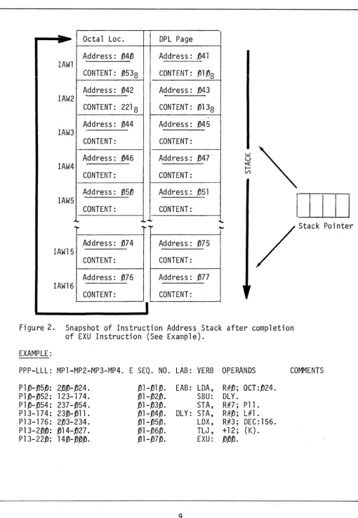
The Instruction Address Stack (lAS) is located in memory and consists of sixteen Instruction Address Words (lAW) of two bytes each. Access to the Stack is under control of a four-bit register called the Stack Pointer. The current instruction address is contained in the lAW indicated by the Stack Pointer.
During sequential instruction operations, the Instruction Address is re-trieved from the lAW, used to locate the current instruction, incremented by two, and inserted back into the lAW. For branch operations, a new Instruction Address is inserted into the current lAW and execution con-tinues with the new address.
1=1
IAW2
IAW3
IAW4
IAW15
IAW16
Octal Loc.
Address: 1)41)
CONTENT: . 053Q U
Address: 1)42
CONTENT: 2218
Address: 1)44
CONTENT:
Address: f)46
CONTENT:
Address: 1)74
CONTENT:
Address: 1)76
CONTENT:
J
OPL Page
Address: 1)41
I CONTENT: .ell·~8 Address: 1)43
CONTENT: tJl38
....
Address: 1)45
CONTENT:
Address: 1)47
CONTENT:
..
Address: 1)75
CONTENT:
Address: '/J77
CONTENT:
I
~~
I I
tI
/ Stack Pointer
Figure 2.. Snapshot of Instruction Address Stack after completion of EXU Instruction (See Example).
EXAMPLE:
PPP-LLL: MP1-MP2-MP3-MP4. E SEQ. NO. LAB: VERB OPERANDS
Pl1)-tJ5fj: 2fjfj-tJ24. PltJ-tJ52: 123-174. PltJ-tJ54: 237-tJ54.
P13-174: 23tJ-tJl1. P13-176: 2tJ3-234.
P13-2tJtJ: tJ14-tJ27. P13-221): 14tJ-tJtJtJ.
EAB: LOA, R#tJ; OCT:tJ24. SBU: OLY.
STA, R#7; Pll. OLY: STA, R#tJ; L#l.
LOX, R#3; OEC:156. TLJ, +12; (K). EXU: tJtJtJ.
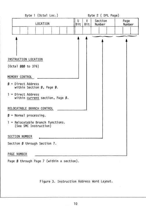
[image:15.618.46.557.28.765.2]Byte 1 (Octal Loc.) Byte 2 ( DPL Page)
LOCATION
I
I
I
INSTRUCTION LOCATION
(Octal
000
to 376)MEMORY CONTROL
o
=
Direct AddressI
I
within Section
0,
Page0.
1
=
Direct Address·I I
within current section, Page
0.
RELOCATABLE BRANCH CONTROL
o
=
Normal processing.1
=
Re1ocatab1e Branch functions. (See SMC Instruction)SECTION NUMBER
Section
0
through Section 7.PAGE NUMBER
U V
Bit Bit
, ,
Page
0
through Page 7 (within a section).Section Number
I
I
Page Number
[image:16.617.52.556.62.771.2]2. REGISTERS:
The Cogar 4 contains one general purpose accumulator that IS eight bits
(one byte) long. Almost all of the nonbranch DPL-l instructions refer to the accumulator. It is the major center for processor activity and the primary pipeline for data flow to and from the memory and the peripheral devices.
The Cogar 4 contains seven one-byte index registers for each memory section available. They are often used as address displacements in indexed addressing, but may also be used as general purpose registers. A few of the DPL-l instructions act directly on the index registers, but there is much more flexibility than those instructions imply because the registers are located in memory. They may thus be addressed by all memory reference instructions. The accumulator can retrieve, manipulate . and restore the contents of any index register.
The hardware condition register contains the results of Test and Compare instructions. It may be set to High, Equal or Low and retains its status until a new Test or Compare is executed. The operation of DPL-l ditional Branch instructions depends on the status of the hardware con-dition register.
3. ADDRESSING:
The Cogar 4 contains 4K, 8K or 16K bytes of memory, with an lAW 16 bits long. Indirect addressing may operate anywhere within this range. The total memory capacity is divided into eight Sections of 2~48 bytes each. requiring 11 bits to fully address. Branch operations (if not preceded by a "SMS" instruction) may refer only to locations within a Section. Each Section is further divided into eight pages of 256 bytes each, requiring eight bits to fully address. Direct addressing (page ~ of the current control section) or relocatable subroutines (branch operations with page ~ assigned) may refer to one page only.
The object formats shown with the instruction descriptions include the following Binary Notations:
Z = 1 bit frame
y = 2 bit frame
X = 3 bit frame
Instruction Addressing:
All instruction addressing is relocatable page oriented. The address
specification~ in octal notation (object)~ is Pnn-LLL where nn = SL~
S is the Section number~ L is the Level number and LLL is the byte location within the page.
All instructions are retrieved from memory using the current Instruction Address Word~ and all instruction addressing involves modification of the
lAW.
For sequential execution of instructions~ one of the sixteen IAW's within the Stack is incremented by two during each instruction cycle. Instruc-tions may be executed sequentially within a Section or across Section boundaries. It is important to note that when instructions cross a Section boundary~ the branch functions~ if executed~ will transfer con-trol to the Section that was previously set. Other functions are not affected. A "Set Memory Section" instruction is used to change the section context of the lAW for branch instructions.
A jump to a new instruction location uses relative instruction addressing by adding or subtracting up to 15 instruction locations to or from the current lAW. A Jump may be across a Section Boundary.
AAA
ADDRESS NOTATIONS
DOD = Absolute Address~ in decimal notation SSS = Symbolic Address
RRR = Symbolic Branch Reference
NNN = Address Adjustment for Symbolic
Addresses~ in decimal notation
Data Addressing:
Data is addressed by an instruction in three different modes: Immediate, Direct and Indexed.
When using the Immediate Addressing Mode, the operand itself, instead of the operand address, is assembled within the instruction as a self-defining literal. The literal represents data rather than an address of data. Literals provide a means of entering constants into a program by specifying the constant in the operand of the instructi.on in which it is used. Immediate Addressing is differentiated from Direct Addressing by the operand form.
Direct Addressing Mode uses the instruction operand as the address of a byte location for all page numbers within level~. This mode is
utilized by specifying in the operand, any form of Direct Address notation. All DPL-l functions may take this form of operand except Class ~ and Class 1 Instructions.
The Indexed Addressing Mode provides a method of addressing data any-where within memory. An Indexed Address is composed of a displacement address contained in a specified index register plus a base address con-tained in the operand. The register specifies the location within a
page and the operand specifies the page within memory. The index register in use may be unchanged, incremented by one or decremented by one follow-ing the indexed operation. There are three forms of register notation used to specify this option. X may be any integer from 1 through 7 ..
R#X
=
Retain Register Value I#X=
Increment Register afterInstruction Execution D#X = Decrement Register after
Instruction Execution
When an overflow occurs (I#X), the overflow bit is lost and the register contains octal ~~~. When an underflow occurs (D#X), the result is the two·s compliment of the underflow count.
4. SYMBOLS:
It is often more convenient to refer to program elements symbolically. In the DPL-3B Assembler, a symbol is a combination of characters used to represent a program element. Symbols are defined through their use in the label field of an instruction or through the EQU pseudo instruction. A Symbol may be used only once in a label field within one program. When a symbol is used as an instruction operand, it must be defined somewhere in the program. A symbol must be comprised of three non-blank aJpha-numeric characters with the first character non-aJpha-numeric. If the first character is lip II , the following characters must be alphabetic. The
total number of symbols plus ORG statements plus page boundaries crossed by sequential program operation is· limited to a maximum of 128.
Address adjustment may be used for convenience and to cut down on the number of symbols defined. A signed numeric adjustment in decimal bytes from
0
to 255 may be appended to a symbolic reference or may be used re-lative to the current location. An "*" (asterisk) is used to indicate the location of the first byte of the current instruction.The I/O Control Instruction micro-codes provide for control, status and data exchange between the processor and its interface devices. Tape channels may be selected, tape motions initiated, and read or write commanded; the keyboard may be read or beeped; the CRT may be enabled or disabled; the I/O interface transmission may be started or stopped, and data or control bytes written. With the CRT enabled, the data content of any memory page which has a section or level number of less than 5 may be displayed in four-line consecutive mode, eight-line consecutive mode, or eight-line interleaved mode. Several status checks are avail-able for the processor to interrogate. Most normal I/O operations will use the I/O Supervisor, but special purpose routines may be constructed from the IOC instructions and there are several operations, like key-board beep, that are not available from the lOS.
5. DPL-1 INSTRUCTION CLASSES:
The DPL-1 instruction set includes all hardware instructions and is div-ided into four general classes covering all types of operations required of a general purpose processor.
Class
0:
Jump and Conditional Exit InstructionsClass 1: Branch, Linkage-Control, and I/O Instructions
Class 2: Data-Transfer and Arithmetic Instructions
Class
0:
Jump Instructions:Jump instructions transfer control within a context to a location
relative. to the current instruction location. All Jump Instructions are conditional and depend on the result of a test of the contents of the accumulator. The test comparison, the test mask, the Jump direction and the jump increment are all specified in the instruction. The Jump in-crement is expressed in the instruction itself as the octal number of two-byte instructions to be jumped. However, the Batch Assembler uses a decimal byte count for the Jump increment. Test results are stored
in the hardware condition register. For the TMJ and TMX instructions, an unconditional Jump or Exit, and the setting of the condition register to equal, can be effected by using a test mask of zero.
Class 1: Branch, Linkage-Control, and I/O Instructions:
Branch instructions transfer control outside a context to any section address. Branch instructions replace the current lAW with a new instruc-tion address. Stack and Branch instrucinstruc-tions introduce a new instrucinstruc-tion address in a new lAW and preserve the contents of the previous lAW for return linkage. Direct Branch instructions may be conditioned by pre-vious test or compare operations. The conditional instructions allow powerful data-dependent decisions to be made. The Exit and the Exit and Branch instructions are used to return from subroutines. They decrement the stack pointer and thus change program control to the next previous lAW.
Class 2: Data Transfer and Arithmetic Instructions:
This class of instructions includes the Load and Store operations that allow data to be moved between memory and the accumulator or index
registers. These instructions use immediate, direct, or indexed address-ing modes. When loadaddress-ing or storaddress-ing usaddress-ing indexed addressaddress-ing, the
specified index register may be automatically incremented or decremented.
The arithmetic instructions in this class include Binary add and subtract operations on the accumulator or the index registers. Immediate, direct, or indexed addressing may be used. Automatic increment or decrement of
Class 3: Boolean and Compare Instructions:
The Boolean instructions in this class include immediate, direct or indexed addressing of And, Inclusive Or, and Exclusive Or operations. The immediate instructions allow for up to seven right circular shifts of the accumulator prior to operation with the literal.
The Compare instructions compare the contents of the accumulator with a location specified by immediate, direct or indexed addressing. Any index register may be compared with a literal. The comparison results are stored in the condition register and may be tested by any following conditional Branch instruction. In indexed addressing of both Boolean and Compare instructions, the specified index register may be auto-matically incremented or decremented.
6. DPL PUNCTUATION:
Rather than an implicit syntax, the DPL grammar provides an explicit syntax by use of punctuation. Four punctuation characters are used: the semi-colon, the comma, the colon and the period.
The semi-colon is used as an imperative terminator or a major field delimiter. It usually separates the instruction field from the operand field.
The comma is used as a minor field terminator. It separates multiple field instructions or operands.
The colon is used as a declarative terminator. It follows instruction labels, pseudo instructions and constant designators.
The period is used as a closing terminator and defines the end of the symbolic instruction.
7. LITERAL NOTATIONS:
Literals that are assigned a value by the DPL-3B Assembler use five forms of address constants in which AAA is a symbolic address. These are: ADC:AAA, ADL:AAA, ADP:AAA, IDP:AAA, and DDP:AAA. These address constants are used primarily to define the actual address of a
symbolic reference. When the literal form ADP, lOP, or DDP is used in conjunction with an R#0 or an R#X, instruction, the DPL page value of AAA is assembled as the operand; either with no indexing tag, or with incrementing or decrementing tag, respectively. If the form ADL
is used, the address location value within the page is assembled as the operand.
When the literal form ADC is used in conjunction with an R#O
instruction, the DPL page value, in increment form, is assembled as the operand. If used in conjunction with an R#X instruction, the symbolic address location within the page is assembled as the operand.
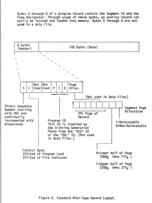
8. STANDARD C4 PROGRAM RECORD (Mini-Tape)
The Standard Mini-Tape Record is comprised of an 8-byte label, generated by the Mini-Write Software Function, followed by 128 bytes of data. The 8-byte label when read into (or written from) memory resides in Page 00,
locations 0308 thru 0378. The first byte of the Record Header contains a sequence number. The sequence number is automatically checked by the Mini-Read Software Function to provide a method of automatically bypassing any nCIG" (Character in Gap). This sequence number may also be used to adjust search counters when utilizing the high-speed
\
\
Bytes 5 through a of a program record contain the Segment ID and the Page Designator. Through usage of these bytes, an overlay record can easily be located and loaded into memory. Bytes 5 through a are not used in a data file.
a bytes (Header)
\
\
S C
I
"'-Not Used
'"
"'-'"
'"
Not Used P
12a Bytes (Data)
"-'"
'"
"-Page I D Alloc.
I
(Not used in Data Files)I
Binary Sequence Number starting with 001 and
JL.--LI--I--I --LI--L-I
-0:.1--1...1
~I
-r-ll
Segment PageJ Allocation
DPL Page of Record _continually
incremented with wraparound
Control Byte.
Program ID.
This ID is inserted by the O-String Generation Phase from the "SEG" ID or the "OVL II ID. (Not used
in data files.)
375=End of Program Load 377=End of File Indicator
I
l=Relocatable O=Non-Relocatable
O=Lower half of Page (OOOa thru 177a )
[image:24.613.56.563.56.730.2]9. SUBROUTINE RELOCATABILITY
A method has been provided to allow the user to write subroutines that may be executed within any Page without re-assembling the subroutine for that Page. By executing a SET Memory Control Command that sets the Relocatable Branch Control (RBC) Bit, any Branch, Stack and Branch or Exit and Branch Instruction given with Page 0 specified in the Branch Address will cause the Branch to occur within the current Section and Page of the program. If any Page other than 0 is specified in the Branch Address, the RBC-Bit is Inactive and a normal Branch function will occur.
10. TAPE I/O CHARACTER QUEUE
For DPL-l instructions that use Immediate Addressing, the following forms may be used in symbolic coding to specify the literal value:
(K)
OCT:NNN
HEX: HH
DEC:NNN
ADP:AAA
IDP:AAA
DDP:AAA
ADL:AAA
ADC:AAA
AAA±NNN
Where K is a valid keyboard character
Where NNN is a one-byte constant in OCTAL notation from ~~~ to 377.
Where HH is a one-byte constant in HEXA-DECIMAL notation from ~~ to FF.
Where NNN is a one-byte constant in DECIMAL notation from ~~~ to 255.
Where AAA is an address constant for a PAGE in symbolic notation (without Auto Indexing).
Where AAA is an address constant for a PAGE in symbolic notation (with Increment Auto. Indexi ng).
Where AM is an address constant for a PAGE in symbolic notation (with Decrement Auto. Indexing).
Where AAA is an address constant for a LOCATION in symbolic notation.
An address constant for labels, in symbolic notation (will generate page or location dependent on the Instruction form).
SECTION III. INSTRUCTION DESCRIPTIONS
The instructions described in this section of the manual are presented in the same order as they appear on the Cogar System 4
Instruction Reference Card, and fall in the following four categories: 1. DPL-1 Instructions. These instructions perform all the data
manipulation and control tasks allowed by the hardware.
2. IDS Commands. These instructions provide access to the standard software I/O routines, using the I/O Supervisor.
3. Pseudo Instructions. These instructions provide programmer control over the DPL-3B Assembler, and the resident monitors. 4. Constants. Byte constants or string constants may be generated
·DPL-l CLASS IJ: JUMP TEST LITERAL AND JUMP
[![]
OBJECT I I SOURCE
I I
00IJJJIJ-LLL I I TLJ, +NNN; Literal. IJIJIJJJ1-LLL I I TLJ, -NN; Literal.
I I I I I I
WHERE: JJ is the jump count in 4 Bit Binary notation, indicating
the number of 2-Byte instructions to be jumped.
AND: LLL is an 8 Bit Literal.
DESCRIPTION:
WHERE: NN is the jump count in decimal notation, indic-ating the number of bytes to be jumped.
NOTE: This jump count must always be an even decimal number (Max:30).
The Accumulator is compared to the byte of immediate data (literal), and the result is indicated in the condition register. Comparison is binary, and all codes are valid. If the resulting condition register is equal, a jump for-ward (+) or a jump backfor-ward (-) up to 15 two-byte instruction locations is
performed. If however the resulting condition register is not equal (high or low), the next sequential instruction is executed. The character in the
Accumulator is not changed. Once set, the condition register remains unchanged until modified by the next jump or compare instruction that reflects a different condition code.
NOTE: .The condition register contains the true arithmetic condition (high or low) after an unsuccessful jump (unequal condition).
HIGH LOW EQUAL
ACCUM
>
ACCUM<
ACCUM=
LITERAL LITERAL LITERAL
TIMING: 3 Microseconds if the jump is not performed. 4 Microseconds if the jump is performed.
EXAMPLE:
PPP-LLL: MP1-MP2-MP3-MP4. E SEQ. NO. LAB: VERB OPERANDS
P15-1J1J0: 1J12-1J15. P15-00l: 1J13-1J16. P15-1J04: 1J1J6-1J15. P15-1J1J6: 1J1J4-1J17.
1Jl-121J.
.01-131J.
1Jl-141J. 1Jl-151J.
TLJ, +11J; (A). TLJ, -11J; OCT:1Jl6. TLJ, +1J6; DEC:1J13. TLJ, +1J4; HEX:0F.
COMMENTS
·DPL-l CLASS~: JUMP TEST MASK AND JUMP
OBJECT ~! SOURCE
001JJ0-MMM
~~lJJ1-MMM , I I
i i TMJ, +NN; LT-MASK. I I TMJ, -NN; LT-MASK.
I I
I I
I I
WHERE: JJ is the jump count in 4 Bit Binary notation, indicating
the number of 2-Byte Instructions to be jumped.
WHERE: NN is the jump count in decimal notation, indic-ating the number of bytes to be jumped.
AND: MMM is an 8 Bit Literal Mask. NOTE: This jump count must always be an even decimal number (Max:30).
DESCRI PTI ON:
The state of the Accumulator bits selected by a mask is used to set the con-dition code.
The byte of Immediate Data (Literal-Mask) is used as an eight-bit mask. The bits of the mask are made to correspond one for one with the bits of the
character in the Accumulator. A mask bit of one indicates that the corresponding Accumulator bit is to be tested. When the mask bit is zero, the corresponding . Accumulator bit is ignored. When any of the Accumulator bits thus selected are zero, the Condition Register is made unequal. When the selected bits are
all-one, the Condition Register is made equal. If the resulting Condition Register is equal, jump forward (+) or jump back (-) up to 15 two-byte in-struction locations. On the resulting Condition Register not equal (high or low), execute the next sequential instruction. The character in the Accumulator is not changed. Once set, the Condition Register remains unchanged until modi-fied by an instruction that reflects a different condition code.
NOTE: The content of the Condition Register is unpredictable after an un-- un-- successful jump (unequal condition). .
TIMING: 3 Microseconds if the jump is not performed. 4 Microseconds if the jump is performed.
EXAMPLE:
PPP-LLL: MP1-MP2-MP3-MP4. E SEQ. NO. LAB: VERB OPERANDS
P1S-010: 050-016.
P15-~12: 051-050.
P15-~14: 076-377.
TMJ, +~8; OCT:~16.
TMJ, -~8; DEC:~40.
TMJ, +3~; HEX:FF.
COMMENTS
'DPL-l CLASS I):
OBJECT
I)I)~-LLL
I I
,
I I I I
I I
I I
I I I I
TEST LITERAL AND EXIT
SOURCE
TLX, 1)~0; Literal.
WHERE: LLL is an 8 bit Literal.
DESCRIPTION:
The Accumulator is compared to the byte of immediate data (literal), and the result is indicated in the Condition Register. Comparison is binary, and all codes are valid. If the resulting Condition Register is equal, then a special form of exit, (conditional exit) is performed, which completes the return linkage established by the last executed stack and branch instruction. The stack pointer is decremented to the preceding stack level, which contains the address of the last stack and branch instruction executed. This address is then incremented by 2 bytes, which establishes the address of the instruction following the stack and branch instruction, and a new location counter value. This value is the new instruction address, where processing continues.
The exit function may return within a section or outside a section without any special consideration, since the stack contains the page and location of the return address.
NOTE: The Condition Register contains the true arithmetic condition (high or low) after an unsuccessful Jump (unequal condition).
HIGH LOW EQUAL
ACCUM
>
ACCUM<
ACCUM=
LITERAL LITERAL LITERAL
TIMING: 3 Microseconds if the Jump is not performed. 4 Microseconds if the Jump is performed.
EXAMPLE:
PPP-LLL: MP1-MP2-MP3-MP4. E SEQ. NO. LAB: VERB OPERANDS
P15-~16: 0~1J-017.
P15-1)2~: 000-013. P15-022: 000-~16.
P15-024: .01)1)-377.
~2-091). ~2-100.
02-11.0. .02-120.
TLX, ~IJIJ; (C). TLX, 000; OCT:,()13. TLX, 01)~; OEC:014. TLX, 1)1)0; HEX:FF.
COMMENTS
·DPL-l CLASS 0:
OBJECT
.04.0-MMM
. TEST MASK AND EXIT
I I
SOURCE
I I
i I TMX, .0.0fJ; LT -MASK. I I
I I
I I
I I
WHERE: MMM is an 8 bit Literal Mask.
DESCRIPTION:
The state of the Accumulator bits selected by a mask is used to set the condition code.
The byte of Immediate Data (Literal-Mask) is used as an eight-bit mask. The bits of the mask are made to correspond one for one with the bits of the char-acter in the Accumulator. A mask bit of one indicates that the corresponding Accumulator bit is to be tested. When the mask bit is zero, the corresponding Accumulator bit is ignored. When any of the Accumulator bits thus selected are zero, the Condition Register is made unequal. When the selected bits are all one, the Condition Register is made equal. If the resulting Condition Register is equal, then a special form of exit, (conditional exit) is performed, which completes the return linkage established by the last executed stack and branch instruction. The stack pointer is decremented to the preceding stack level, which contains the address of the last stack and branch instruction executed. This address is then incremented by2 bytes, which establishes the address of the instruction following the stack and branch instruction, and a new location counter value. This value is the new instruction address, where processing continues.
The exit function may return within a section or outside a section without any special consideration, since the stack contains the page and location of the return address.
NOTE: The content of the Condition Register is unpredictable after an un-- un-- successful Jump (unequal condition).
TIMING: 3 Microseconds if the Jump is not performed. 4 Microseconds if the Jump is performed.
EXAMPLE:
PPP-LLL: MP1-MP2-MP3-MP4. E SEQ. NO. LAB: VERB OPERANDS
P15-026: 040-.01.0. .02-18.0. TMX, 0.0.0; OCT: IJlIJ . P14-.03.0: .040-31.0. .02-19.0. TMX, 00.0; DEC:2.0.0. P15-032: .04.0-24.0. .02-2fJ.0. TMX, (1.0.0; HEX:AIJ.
COMMENTS
.DPL-l CLASS 1: BRANCH
OBJECT I I
I I
l.0X-YXY.0 1 1 I I
I I
I I I I
WHERE: l.0X is the command, in which X is the page.
AND: YXY is a 7 bit address.
DESCRIPTION:
BRANCH UNCONDITIONAL
BRU
SOURCE
RRR+NNN. , Pnn; LLL.
*+NNN.
WHERE: RRR is a symbolic address AND: NNN is a decimal byte
dis-placement.
AND: nn is a decimal page. AND: LLL is a decimal location AND: * is the location of the
in-struction itself.
The unconditional branch is performed by introducing a branch address as a new instruction address, regardless of the setting of the Condition Register.
The Branch Address may be represented in symbolic notation, as an absolute
address; or as a relative address. The Branch Address may be any location within the current section. "OUT-Of-SECTION" branching is achieved by preceding the branch instruction with a SET MEMORY SECTION (SMS) instruction, or a SET memory SECTION & CONTROL (SSC) instruction. "WITHIN-A-PAGE" branching relocatability is achieved by preceding the branch instruction with a SET MEMORY CONTROL (SSC) instruction in which the RELOCATABLE BRANCH CONTROL (RBC) bit is set.
(i.e.: C#l or C#3). The hardware condition register remains unchanged after execution of a branch function.
TIMING: 4 Microseconds.
EXAMPLE:
PPP-LLL: MP1-MP2-MP3-MP4. E SEQ. NO. LAB: VERB OPERANDS
P15-.034: 1.05-.042. .03-.03.0. BRU; INl. P15-.036: 1.05-.036. .03-.04.0. BRU; *+.0. P15-.04.0: 1.07-.0.0.0. .03-.05.0. BRU, P15; .0.0.0. P15-.042: 15.0-.0.0.0. .03-.06.0. IN1: SMS; S#.0 . P15-.044: 1.06-144. .03-.07.0. BRU, P.06; 1.0.0.
COMMENTS
WITHIN A SECTION
'DPL-l CLASS 1: BRANCH
OBJECT I I
I I
! !
BRANCH ON EQUAL
SOURCE
H)X-YXYl I I BRE
I I
RRR+NNN.
, Pnn -; LLL. *+NNN.
I I i i
WHERE: l~X is the command, in which X is the page.
AND: YXY is a 7 bit address.
DESCRIPTION:
WHERE: RRR is a symbolic address. AND: NNN is a decimal byte
dis-placement.
AND: nn is a decimal page. AND: LLL is a decimal location. AND: * is the location of the
in-struction itself.
The conditional branch instruction, branch on equal, is performed when the con-dition register, set by a previous compare or test instruction, is found to be equal. If this condition is not satisfied, the next sequential instruction is executed. The conditional branch is performed by introducing a branch address as a new instruction address.
(Refer to "BRU" for Basic Rules of Branching).
TIMING: 3 Microseconds if the branch is not performed. 4 Microseconds if the branch is performed. EXAMPLE:
PPP-LLL: MP1-MP2-MP3-MP4. E SEQ. NO. LAB: VERB OPERANDS
P15-~46: 1~5-~51. ~3-13~ BRE; IN2.
P15-~5~: 15~-~~~. ~3-14~. IN2: SMS; S#~.
P15-~52: 34~-2~~. ~3-15~. CPA, R#~; OCT:2~~.
P15-~54: 1~6-145. ~3-16~. BRE, P~6; l~~.
P15-~56: 15~-~1~. ~3-17~. SMS; S#1.
'DPL-l CLASS 1: BRANCH BRANCH ON HIGH
I
BRH
I
OBJECT I I SOURCE
I I
I I RRR+NNN.
llX-YXY.0 I I BRH , Pnn; LLL.
.
WHERE: 11 Xis the command, in which X is the page. AND: YXY is a 7 bit address.
DESCRI PTION:
I I
I I
I I
*+NNN.
WHERE: RRR is a Symbolic address. AND: NNN is a decimal byte
dis-placement.
AND: nn is a decimal page. AND: LLL is a decimal location. AND: * is the location of the
in-struction itself.
The conditional branch instruction, branch on high, is performed when the con-dition register, which has been set by a previous compare or test instruction, is found to be high. If this condition is not satisfied, the next sequential instruction is executed.
(Refer to "BRU" for Basic Rules of Branching).
TIMING: 3 Microseconds if the branch is not performed. 4 Microseconds if the branch is performed. EXAMPLE :
PPP-LLL: MP1-MP2-MP3-MP4. E SEQ. NO. LAB: VERB OPERANDS P15-.06.0: 115-.062. .04-.03.0. BRH; *+1)2. P15-1)62: 151)-.0.0.0. .04-.041). IN3: SMS; S#1) .
P15-1)64: 340~2.0.0. .04-1)51). CPA, R#.0; OCT:21).0. P15-.066: 116-144. 1)4-.06.0. BRH, P1)6; 1.0.0. P15-07.0: 15.0-.01.0. .04-.07.0. SMS; S#1.
'DPL- 1 CLASS 1: BRANCH BRANCH ON LOW
~
OBJECT I I SOURCE
I I I
i I RRR+NNN. 11 X- YXY1 I I BRL , Pnn; LLL.
I I
I I I I
WHERE: 11X is the command, in which X is the page.
AND: YXY is a 7 bit address.
DESCRIPTION:
*+NNN.
WHERE: RRR is a Symbolic address. AND: NNN is a decimal byte
dis-placement.
AND: nn is a decimal page. AND: LLL is a decimal location. AND: * is the location of the
in-struction itself.
The conditional branch instruction, branch on low, is performed when the con-dition register, set by a previous compare or test instruction, is found to be low. If this condition is not satisfied, the next sequential instruction is executed. The conditional branch is performed by introducing a branch address as a new instruction address.
(Refer to IIBRU II for Basic Rules of Branching)
TIMING: 3 Microseconds if the branch is not performed. 4 Microseconds if the branch is performed.
EXAMPLE:
PPP-LLL: MP1-MP2-MP3-MP4. E SEQ. NO. LAB: VERB OPERANDS
P15-1J72: 115-075.
04-131J.
BRL; IN4. P15-074:150-001J.
04-141J.
IN4: SMS; S#IJ.P15-1J76:
341J-21J1J.
1J4-150.
CPA, R#IJ; OCT:200. P15-100: 116-145.04-161J.
BRL, P06;11J1J.
P15-102: 150-010.
04-171J.
SMS; S#1.COMMENTS
.DPL-l CLASS 1: BRANCH
OBJ E CT I I
I I
STACK AND BRANCH UNCONDITIONAL
SOURCE
12X-YXY.fl I I SBU
I I
RRR+NNN. , Pnn -; LLL.
*+NNN.
WHERE: 12X is the command, in which X is the page~
AND: YXY is a 7 bit address.
I I
I I I I
WHERE: AND: AND: AND: AND:
RRR is a symbolic address.
NNN is a decimal byte displacement. nn is a decimal page.
LLL is a decimal location.
* is the location of the instruc-ti on itself.
The Stack and Branch Unconditional Instruction is performed regardless of the setting of the condition register.
DESCRIPTION:
The stack and branch instructions are in contrast with the branch instructions, in that the stack and branch instructions preserve the current value of the location counter which is present in the current stack; this is performed by incrementing the stack pointer to the next stack level and creating a new location counter value containing the branch address as a new instruction ad-dress, within that stack. Thus, the return linkage between sub-routines is established. For the stack and branch function there are sixteen levels of stacks that the stack pointer can address, of which fifteen levels of stacks may temporarily preserve the return linkages for fifteen levels of stack and
branchi ng.
TIMING: 3 Microseconds EXAMPLE:
PPP-LLL: MP1-MP2-MP3-MP4. E SEQ. NO. LAB: VERB OPERANDS COMMENTS P1S-l,f)4: 12S-112. ,f)S-.fl4/l. SBU; INS. WITHIN A P15- 1,f)6: 125-112. ,f)5-.fl5,f). SBU; *+.fl4. SECTION P15-11/l: 1 27-.fl.fl,f). ,f)5-.fl6.fl. SBU, P15; .fl.fl.fl.
'DPL-l CLASS 1: BRANCH
OBJECT
I I I I
STACK AND BRANCH EQUAL
SOURCE
12X-YXYl I I SBE
I I
RRR+NNN. , Pnn; LLL.
*+NNN.
I I
1 1
WHERE: 12X is the command, in which X is the page.
AND: YXY is a 7 bit address.
DESCRIPTION:
WHERE: RRR is a symbolic address. AND: NNN is a decimal byte
displace-ment.
AND: nn is a decimal page. AND: LLL is a decimal location. AND: * is the location of the
in-struction itself.
The conditional stack and branch, stack and branch equal, is performed when the condition register, set by a previous compare or test instruction, is found to be equal. If the condition is not satisfied, the next sequential instruction is executed.
(Refer to "SBU" for Basic Rules of Stack and Branching).
TIMING: 3 Microseconds if the stack and branch is not performed. 4 Microseconds if the stack and branch is performed.
EXAMPLE:
PPP-LLL: MP1-MP2-MP3-MP4. E SEQ. NO. LAB: VERB OPERANDS COMMENTS
.DPL-l CLASS 1: BRANCH STACK AND BRANCH ON HIGH
OBJECT
! !
SOURCEI I
13X-YXY.0 I I SBH I I
RRR+NNN. , Pnn; LLL.
*+NNN.
WHERE: 13X is the command, in which X is the page. AND: YXY is a 7 bit address.
DESCRI PTION:
I I
I I
I I
WHERE: RRR is a symbolic address. AND: NNN is a decimal byte
displace-ment.
AND: nn is a decimal page. AND: LLL is a decimal location. AND: * is the location of the
instruction itself.
The conditional stack and branch, stack and branch on high, is performed when the condition register, set by a previous compare or test instruction, is found to be high. If the condition is not satisfied the next sequential instruction is executed.
(Refer to IISBU II for Basic Rules of Stack and Branching)
TIMING: 3 Microseconds if the stack and branch is not performed. 4 Microseconds if the stack and branch is performed.
EXAMPLE:
PPP-LLL: MP1-MP2-MP3-MP4. E SEQ. NO. LAB: VERB OPERANDS COMMENTS
.DPl-l CLASS 1: BRANCH STACK AND BRANCH ON lOW
OBJECT
!!
SOURCE13X-YXYl
I I I !
I I SBL
I I
I I
I I
WHERE: 13X is the command, in which X is the page.
AND: YXY is a 7 bit address.
DESCRIPTION:
RRR+NNN. , Pnn; LLL.
*+NNN.
WHERE: RRR is a symbolic address. AND: NNN is a decimal byte
dis-placement.
AND: nn is a decimal page. AND: LLL is a decimal location. AND: * is the location of the
in-struction itself.
The conditional stack and branch, stack and branch on low, is performed when the condition register, set by a previous compare or test instruction, is found to be low. If the condition is not satisfied the next sequential instruction is executed.
(Refer to "SBU" for Basic Rules of Stack and Branching)
TIMING: 3 Microseconds if the stack and branch is not performed. 4 Microseconds if the stack and branch is performed.
EXAMPLE:
PPP-LLl: MP1-MP2-MP3-MP4. E SEQ. NO . lAB: VERB OPERANDS COMMENTS
'DPL-l CLASS 1: BRANCH EXIT AND BRANCH
OBJECT
! !
SOURCEI I
16X-YXY~ I I EXB
I I
RRR+NNN. , Pnn; LLL.
*+NNN.
WHERE: 16X is the command, in which X is the page. AND: YXY is a 7 bit address.
DESCRI PTI ON:
I I
I I I I
WHERE: AND: AND: AND:
RRR is a symbolic address.
NNN is a decimal byte displacement. nn is a decimal page.
LLL is a decimal location.
The exit and branch instruction combines the functions of the exit instruction and the branch unconditional instruction. This form of exit does not perform the return linkage established by the preceding stack and branch instruction. The stack pointer is decremented to the preceding stack level. The address specified in the operand is then used to establish a new location counter value within that stack. This value is the new instruction address within the current section, where processing continues.
TIMING: 4 Microseconds
EXAMPLE:
PPP-LLL: MP1-MP2-MP3-MP4. E SEQ. NO. LAB: VERB OPERANDS COMMENTS
P15-154: 165-156. ~7-~5~. EXB; *+~2. WITHIN SECT.
P15-156: 15~-~~~. ~7-~6~. SMS; S#fJ. OUT OF A
'DPL-l CLASS 1: BRANCH EXIT UNCONDITIONAL
OBJECT. I I SOURCE ..
I I
140-00~ I I EXU; ~~~. I I
I I I I I I
. WHERE: 140 is the command . AND: 000 is the 8-Bit Operand
DESCR I PTI ON:
This form of exit, exit unconditional, performs the return linkage established by the last executed stack and branch instruction. The stack pointer is decre-mented to the preceding stack level, which contains the address of the last stack and branch instruction executed. This address is then incremented by 2 bytes which establishes the address of the instruction following the stack and .branch instruction, and a new location counter value. This value is the new
instruction address, where processing continues.
The exit function may return within a section or outside a section without any special consideration, since the stack contains the page and location of the return address.
The condition register is not changed by this instruction.
TIMING: 4 Microseconds. EXAMPLE:
PPP-LLL: MP1-MP2-MP3-MP4. E SEQ. NO. LAB: VERB OPERANDS
P15-162: 150-000. 07-130. SMS; S#0. P15-164: 126-144. 07-140. SBU; OUT.
*07-150.
07-160. ORG: P06, 100. P06-144: 213-006. 07-170. OUT: LOA, 1#3; P01. P06-146: 140-000. 07-180. EXU; 000.
COMMENTS
LINK OUT OF A SECTION
·DPL-l CLASS 1: BRANCH SET MEMORY SECTION
OBJECT
!!
SOURCEI I I I
l5.0-.0X.0 I ISMS; S#X.
I I I I
I I
WHERE: X is the section number (.0-7). DESCRIPTION:
The set section instruction provides a means of transferring control from the current section to an outside section. A branch function (Branch, Stack
&
Branch or Exit & Branch) preceded by an SMS command will transfer control to the address defined by the branch address and the section specified in the set section operand.
Note that once the SMS instruction has been executed, transfer to that section will only be made when an unconditional branch function is executed or a
conditional branch function that is found to be true. The condition register is not changed by this instruction. TIMING: 4 Microseconds.
EXAMPLE:
PPP-LLL: MP1-MP2-MP3-MP4. E SEQ. NO. LAB: VERB OPERANDS SMS; S#.0. BRU, P.02; .0.0.0.
COMMENTS SET SECTION .0