6XEV\VWHP
information contained herein are the property of EXABYTE Corporation. No part of this document may be reproduced, transmitted, transcribed, stored in a retrieval system, or translated into any language or computer language in any form or by any means, electronic, mechanical, magnetic, optical, chemical, manual, or otherwise, without the express written permission of EXABYTE Corporation, 1745 38th Street, Boulder, Colorado 80301.
Disclaimer
EXABYTE Corporation makes no representation or warranties with respect to the contents of this document and specifically disclaims any implied warranties of merchantability or fitness for any particular purpose. Further, EXABYTE Corporation reserves the right to revise this publication without obligation of EXABYTE Corporation to notify any person or organization of such revision or changes.
1. General . . . 1
1.1. Purpose . . . 1
1.2. Contents . . . 1
1.3. Related Documents . . . 1
2. Description of the EXB-8200 . . . 2
2.1. Major Components of the EXB-8200 . . . 2
2.2. Integration of the EXB-8200 . . . 3
2.3. A Solution for Secondary Data Storage . . . 3
3. Overview of Helical Scan Technology . . . 3
3.1. Advantages of Helical Scan Technology . . . 4
3.2. Recording Methods: Parallel vs. Helical Scan . . . 4
4. 8mm Tape Characteristics . . . 8
5. Definitions . . . 9
6. Component Interaction . . . 15
6.1. Read/Write (RW) Card . . . 16
6.2. Clock and Detection (CD) Card . . . 17
6.3. Data Flow (DF) Card . . . 18
6.4. Microprocessor (MX) Card . . . 20
6.5. Data Buffer (DB) Card . . . 22
6.6. Servo (SV) Card . . . 23
7. Functional Description . . . 27
7.1. Write . . . 27
7.2. Read Back Check . . . 28
7.3. Rewrite . . . 28
Figures
Figure 1. Helical Scan Track Layout5 Figure 2. Helical Scan Recording6
Figure 3. The EXB-8200 Cartridge Tape Subsystem9
Figure 4. EXB-8200 CTS Printed Circuit Board Block Diagram15 Figure 5. Filemarks17
Figure 6. Write Data Flow20 Figure 7. Read Data Flow20
Tables
1. General
1.1. Purpose
This document provides an introduction to the EXB-8200 Cartridge Tape Subsys-tem, including an overview of helical scan technology, characteristics of 8mm tape, and a description of the EXB-8200 and its components and how they interact.
1.2. Contents
This document is divided into the following sections:
■ Section 2 contains a description of the EXB-8200 Cartridge Tape Subsystem. ■ Section 3 contains a list of related documents.
■ Section 4 contains a brief discussion of helical scan technology. ■ Section 5 describes the characteristics of 8mm tape.
■ Section 6 contains definitions of important terms related to the EXB-8200.
■ Section 7 contains an in-depth description of the six printed circuit boards that comprise the EXB-8200 and how they interact.
■ Section 8 contains a functional description of the write, read back check, rewrite, and read operations of the EXB-8200.
1.3. Related Documents
For information on ANSI 8mm tape format, refer to the ANSI Helical-Scan Digital
Computer 8mm Tape Cartridge Format Standard, X3B5/89-136.
For information on SCSI-1 protocol, refer to the ANSI document, Small Computer
For further information on the EXB-8200, refer to the following documents:
■ EXB-8200 8mm Cartridge Tape Subsystem Product Specification, Part
Number 510005-xxx
■ EXB-8200 8mm Cartridge Tape Subsystem User’s Manual, Pa rt
Number 510006-xxx
2. Description of the EXB-8200
The EXABYTE EXB-8200 8mm Cartridge Tape Subsystem is a high-performance, high-capacity 8mm cartridge tape subsystem that incorporates an integral Small Computer System Interface (SCSI).
The EXB-8200 is a true digital data storage device, derived from 8mm video recording technology (helical scan technology), with performance improvements and the additional functions necessary for data processing purposes.
Advanced helical scan technology provides very high recording density and data storage capacity. The industry-standard 8mm tape cartridge used by the EXB-8200 is removable and rewriteable. The largest capacity 8mm tape cartridge stores more than 2,000 megabytes of formatted user data.
The EXB-8200 conforms to the dimensions of the industry standard 5.25-inch, full height form factor.
2.1. Major Components of the EXB-8200
The EXB-8200 consists of the following major components:
■ 8mm tape transport mechanism and recording channel
■ Servo
■ Formatter
■ Controller
2.2. Integration of the EXB-8200
Helical scan-based cartridge tape drives can be integrated into many computer systems through the implementation of an industry standard I/O interface such as SCSI. By designing a sequential access device to operate using the SCSI-1 protocol, the integration of helical scan tape devices into a given system is much simpler and consequently reduces the time to market for data storage products of this type. The implementation of an integral SCSI controller/formatter allows tasks normally conducted by the host to be performed by the tape drive, thereby enhancing overall system performance.
In addition to performing all normal error recovery procedures, the architecture of the EXB-8200 supports SCSI bus transfer rates of up to 1.5 megabytes per second. Assuming the host is capable, the EXB-8200 can maintain a continuous data transfer rate of 246 kilobytes per second. An internal, 256-kilobyte, speed-matching cache buffer provides the drive with virtual start-stop performance. Additionally, the tape transport’s reel/capstan servo system is capable of performing a fast-forward file search at 10 times nominal velocity while a rewind operation is 75 times nominal.
2.3. A Solution for Secondary Data Storage
Helical scan recording technology, when combined with high-quality, 8mm tape media, mainframe-like mass storage device architecture, and standard SCSI, pro-duces an attractive solution to the current void in high-capacity secondary data storage. This technology has paved the way for tape drive manufacturers such as EXABYTE to design, develop, manufacture, and market a high-capacity, remov-able-media tape cartridge subsystem.
3. Overview of Helical Scan Technology
Helical scan recording involves storing or retrieving data from a magnetic tape using a rotating head assembly. The term “helical” refers to the spiral pattern in which the recording head is rotated. Tracks of data are stored on tape at an angle relative to the edge of the tape, as compared with most stationary head devices, which store data on tracks parallel to the edge of the tape.
According to the 8mm Video Council, helical scan recording using 8mm tape is “. . . the culmination of decades of development—the crowning achievement of years of audio/visual evolution.” Only in the last few years has the computer industry had the opportunity to take advantage of such a mature technology.
In 1987, EXABYTE’s unique implementation of helical scan technology enabled tape capacity to meet and exceed that of disk. This technological breakthrough created the ultimate secondary storage device and made unattended backup an obtainable feat, thereby dramatically reducing the cost of performing this time-con-suming and expensive task for the users of even the largest of today’s computer systems.
3.1. Advantages of Helical Scan Technology
Helical scan recording offers many advantages over stationary head recording. The principal advantages are as follows:
■ Increased areal recording densities ■ Small physical size
■ Gentle tape handling ■ Low power consumption ■ High reliability
■ Affordable cost
The availability of high-quality, low-cost media is one important advantage that helical scan technology offers over other high-density, removable-medium technolo-gies. At a cost of less than one penny per megabyte of stored information, helical scan-based cartridge tape drives have surpassed all other removable-medium devices and technologies.
3.2. Recording Methods: Parallel vs. Helical Scan
Track length and density. The track density for traditional stationary head, parallel
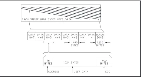
By comparison, 8mm helical scan recorders write very narrow, 25-micron (0.025 mm) tracks at an acute angle of approximately five degrees with respect to the edge of tape. In this way, a track length is created that is almost nine times longer than the width of the tape. Tracks can be accurately positioned by the geometry of the tape path to very precise minimal tolerances, thus increasing tracks per inch. When combined with a high linear flux density, the result is an areal density of 35.4 megabits per square inch.
Figure 1 shows the layout of a helical scan recorded track as produced by the EXB-8200.
With helical scan recording, the tolerances required in the manufacturing of metal laminate are greatly reduced because only one track needs to be recorded per revolution of the head drum assembly. An embedded, track-following servo can then be used to keep the tape aligned with the head.
Figure 1
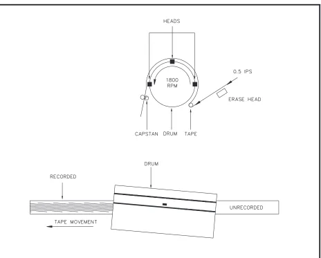
Figure 2 shows the position of the tape and recorded tracks, in relation to the recording head, in the helical scan recording process.
Data throughput. Not only does helical scan recording increase the number of
tracks per inch, it increases the data throughput as well. By using a head that rotates on a drum at 1,800 rpm and moving the tape at one-half inch per second, an effective head-to-tape velocity of nearly 150 inches per second is attained. (See the calculation of tape velocity on the following page.) This results in an average data transfer rate of approximately 246 kilobytes per second for a typical device capable of storing more than 2,000 megabytes of data on standard 8mm media.
Figure 2
Tape velocity. In conventional tape systems, the relative velocity necessary to
produce read signals between the recording head and the tape is provided by moving tape at a relatively high velocity. The power and associated cooling that is required by these types of systems to start or stop a tape reel in short intervals of time is correspondingly high. Furthermore, the acceleration/deceleration forces that act on the tape when run at velocities as high as 200 inches per second require that the tape be relatively strong and thick.
By comparison, helical scan recording mechanisms move tape at very low linear velocities in the range of 0.39 to 0.55 inches per second; consequently, forces acting on the tape are correspondingly low. In this way, gentle tape handling is achieved, minimizing wear on the media.
The relative velocity between the head and tape incorporated in helical scan recording is maintained by mounting the heads on a constantly rotating drum. This provides excellent velocity control, minimizes power, and allows very slow, low-stress tape motion.
The following is the head-to-tape velocity calculation for the EXB-8200.
Empirical formula: πr * rps = ips
Drum radius (r) = 20 mm
Drum circumference (2πr) = 125.7 mm Drum speed = 1,800 rpm / 60 sec = 30 rps
125.7 mm * 30 rps = 3,771 mm/sec
4. 8mm Tape Characteristics
Magnetic recording tapes used in the commercial audio and video industry and those used for computer data storage share several physical characteristics that accommo-date high bit density recording. Generally, high-density recording on tape requires a very thin recording layer of less than 4 microns and a correspondingly smooth base film, as well as a high coercivity magnetic material.
The 8mm metal particle tape used in advanced helical scan recorders offers vastly improved magnetic performance specifications over the conventional chromium dioxide tape used in previous systems. The super-fine metal particles found in the magnetic layer of 8mm tape allow for very high recorded flux densities—as high as 80,000 flux transitions per inch. These recorded flux densities are possible because the 8mm metal particle tape has a coercivity of 1,500 Oersteds and a magnetic recording layer of only 2.5 microns. A coercivity of 1,500 Oersteds implies that the media shelf life is greater than that of other tape media with lower coercivity values. In contrast, typical chromium dioxide-coated tape media used for data storage on 9-track tape drives has a coercivity of approximately 300 Oersteds and a magnetic recording layer of 6 microns. This amounts to a difference of five times the Oersted rating and greater than two times the thickness of 8mm metal particle tape.
A 3480-type chromium dioxide tape media, considered the state-of-the art in tape media for data processing applications, has a coercivity of 520 Oersteds (three times less than 8mm metal particle tape) and a magnetic recording layer of 3.6 microns. These differences in the magnetic properties of 3480-type chromium dioxide and 8mm metal particle tape media account largely for the disparity in the present recording densities.
Note: EXABYTE recommends the EXATAPETMdata cartridges for use with all EXABYTE products. These data cartridges are currently available for purchase through EXABYTE, and come in the following sizes:
■ EXATAPETM15m (equivalent to the P6-15 data cartridge)
5. Definitions
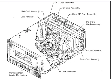
[image:15.612.85.552.165.500.2]This section contains definitions of important terms relating to the EXB-8200. Figure 3 shows the location of the major components of the EXB-8200.
ATM Analog tape mark. Part of a filemark consisting of 11 consecutive tracks of servo data. It is used, together with DTMs and erased gaps, to position the tape. Buffer Memory Interface Provides simultaneous read-while-write access to the
dynamic RAM for both the IPORT and DPORT, and additionally provides dynamic memory refresh at regu-lar intervals.
Figure 3
Buffered Mode One of two methods (see Non-Buffered Mode) used when writing data to tape.
When writing data to tape in buffered mode, data is stored in buffer memory until the amount of data in the buffer exceeds the Motion Threshold value. During a read operation, read ahead is performed, and as a result all data requested from tape is transferred to the host immediately.
CD Card Clock and Detection card.
CRC Cyclic Redundancy Check. Used during the read back check process to determine accuracy of data written to or recovered from tape.
DB Card Data Buffer card.
DF Card Data Flow card.
Disconnect When the EXB-8200 is logically (not physically) de-tached from the host. During a read operation, a dis-connect is automatically performed when the EXB-8200 is sending data to the buffer faster than the host can read it. During a write operation, a disconnect is automatically performed when the EXB-8200 is writing data to tape faster than the host can send it. DPATH The data path from the host to tape.
DPORT A bi-directional port connected to the DF card and the conduit for data transfer between the DB card and the DF card.
Erased Gap Part of a filemark that does not contain any information. It is used, together with ATMs and DTMs, to position the tape. A short filemark has an erased gap that occu-pies the space of 39 tracks; a long filemark has an erased gap that occupies the space of 249 tracks. Erase Head The head on the EXB-8200 that erases data and other
information (e.g., long filemarks). The erase head per-forms only full tape width erases. See Figure 2 for the location of the erase head.
Filemark Information on tape that provides means for faster performance during file searches. A filemark consists of an erased gap, an ATM, and a DTM, and can be either short or long. A short filemark occupies the space of 60 tracks (491 KBytes); a long filemark occupies the space of 270 tracks (2.21 MBytes). A short filemark cannot be overwritten.
Header Information Information associated with a block of data that de-scribes what that data is. Each block of data has 14 bytes of header information associated with it.
IPORT A bi-directional port connected to the SCSI Module. The conduit for data and control information between the SCSI Module and the LSI Module. Data received from the host passes through the SCSI Module to the IPORT of the LSI Module and eventually is written to tape. Data from tape to the host flows through the IPORT to the SCSI Module for transfer to the host.
KBytes Kilobytes.
LSI Module A bi-directional device that provides buffer manage-ment, data routing through the DB card, and interfacing to the microprocessor on the MX card and the DF card. Motion Threshold Value A buffer value measured in kilobytes. The Motion Threshold value relates to data transfers between buffer and tape. When the amount of data in buffer memory exceeds the Motion Threshold value, the head drum spins up, commencing read and write operations. This value is user-selectable; the power-on default value is 128 KBytes.
MX Card Microprocessor card.
Non-Buffered Mode One of two methods (see Buffered Mode) used when writing data to tape.
When writing to tape in the non-buffered mode, data is immediately transferred from buffer to tape and the Motion Threshold value ignored.
NRZI Non-Return to Zero/Inverted. A method employed by the EXB-8200 to convert analog data to digital data. Read Transfer of data from tape to buffer.
When the buffer is emptied to the point where the amount of available space in the buffer exceeds the Motion Threshold value, the head drum spins up and begins refilling the buffer from tape.
If a SCSI disconnect was performed previously and there is more data to be transferred, the EXB-8200 reconnects to the host. Data is transferred to the host when the amount of data in the buffer exceeds the Reconnect Threshold value.
Read Back Check Performed by the read back check head, this is the process of reading data just written to tape to check for accuracy. If a block of data on a track is not accurate, the block is scheduled to be rewritten to tape 11 blocks later (see Rewrite).
Read Back Check Head One of the three heads on the rotating head assembly of the EXB-8200. Performs a read back check on data to be written to or read from tape.
Reconnect When the EXB-8200 is logically re-attached to the host for a read or write operation (see Disconnect).
Rewrite Refers to the writing of a block (1 kilobyte) of data that did not write accurately on a previous try, as deter-mined by the read back check process. If a block of data is determined to be inaccurate, that block is scheduled for a rewrite to tape 11 blocks later. After nine at-tempted rewrites (10 write attempts total) of a single block of data, a permanent write error is reported by the EXB-8200. Also, if 40 blocks of data at any one time are scheduled to be rewritten, a permanent write error is reported by the EXB-8200.
Rotating Head Assembly Contains the three heads of the EXB-8200 drum: 1) write/read head, 2) read back check head, and 3) servo head.
RW Card Read/Write card.
SCSI Chip The Western Digital WD33C93A chip that is part of the SCSI Module.
SCSI Module A bi-directional device that provides the SCSI bus protocol functions and also transfers data to and from the IPORT of the LSI Module.
Servo Data Found at the beginning of each track—the servo area—of data. The servo area consists of four servo zones of 300 bytes each. During a read operation, servo data is read to determine the appropriate tape velocity. Servo Head One of the three heads on the rotating head assembly of the EXB-8200. During a read operation only, this head reads the servo data from tape. This data controls tape velocity.
Write Transfer of data from buffer to tape.
When the amount of data in the buffer exceeds the Motion Threshold value, the head drum spins up and all the data in the buffer is transferred to tape. Unless the amount of data in the buffer exceeds the Motion Threshold value, the head drum will not spin up. If a SCSI disconnect was performed previously and there is more data to be transferred, the EXB-8200 reconnects to the host and accepts more data from the host when the buffer is emptied to the point where the amount of available space in the buffer exceeds the Reconnect Threshold value.
6. Component Interaction
[image:21.612.85.553.221.639.2]The following sections describe the functions of the six cards that comprise the electronics of the EXB-8200 (see Figure 3 for the location of these cards in the EXB-8200).
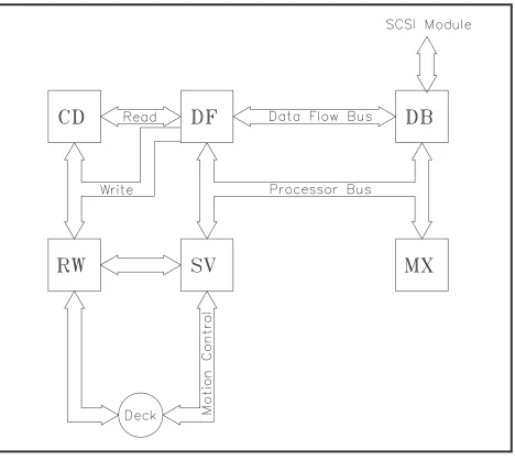
Figure 4 indicates the basic flow of information and control between the six cards and the EXB-8200.
Figure 4
6.1. Read/Write (RW) Card
The Read/Write (RW) card records and recovers digital and servo data on tape, through the rotating head assembly. The RW card interfaces with: 1) the rotating head assembly located on the tape deck, 2) the CD card, 3) the DF card, and 4) the SV card.
Write. A write operation starts with writing the servo and digital data with the
write/read head and performing a read check of the digital data with the read back check head. The read back check occurs after the digital data is written, to minimize crosstalk. The servo capstan control system maintains a constant tape velocity while in a write mode.
Read. A read operation is initiated by the servo head reading servo data, which is
amplified and filtered by the RW card. This causes the servo control system to lock the tape motion to a tracking condition. The write/read head and the read back check head are on track and can recover the recorded digital data. The data read by the read back check head is redundant and provides a way for error recovery without a tape backhitch operation.
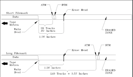
Filemarks. A means for faster performance during file searches is accomplished by
providing the ability to have filemarks written to tape. A filemark consists of an erased gap, an analog tape mark (ATM), and a digital tape mark (DTM). The erased gap is 39 tracks long for a short filemark and 249 tracks long for a long filemark. The erased gap of 249 tracks for a long filemark enables overwrite operations. The 249-track erased gap allows the erase head to be positioned to erase only the ATM, DTM, and data tracks after the long filemark (see Figure 5).
The ATM consists of 11 consecutive tracks of servo data. The servo system detects ATMs while moving tape forward or backward. The DTM consists of 10 identical tracks of filemark information.
6.2. Clock and Detection (CD) Card
The Clock and Detection (CD) card provides the following functions: 1) digitizing of the analog read data, 2) read signal amplitude sensing, 3) servo write data sine wave generation, and 4) servo current diagnostic detection. The CD card interfaces with the RW, DF, and SV cards.
Write. The function of the CD card during a write operation is to participate in the
writing of servo data. The servo data is written in one of four servo zones within the servo area. At the proper time, the SV card generates a 184-KHz square wave that is transferred to the CD card where the signal is transformed into a sine wave. The 184-KHz sine wave is then transferred from the CD card to the RW card to be written to tape via the write/read head.
[image:23.612.84.551.87.357.2]As the servo data is being written to tape, a servo data write current signal operation is generated by the RW card and sent to the CD card where it is checked for magnitude, duration, proper timing, and any stray bits that may have been written to tape. This information is then transferred to the SV card.
Read/Read Back Check.The data path for a Read command and the Read Back
Check operation during a Write command is the same. The analog read data from tape is amplified and equalized on the RW card before being sent to the CD card.
Amplitude Sensor. The analog read data goes through an amplitude sensing circuit
on the CD card that monitors signal magnitude. During a Read operation, if the signal of a block of data is below 25 percent of the original signal amplitude, the ECC process is triggered. During a Read Back Check operation, if the signal of a block of data is below 35 percent of the original signal amplitude, that block is defined as bad and scheduled for a rewrite.
For all operations, the amplitude sense output is used as a gate for the phase corrections to the phase locked loop. The analog read data from the RW card goes through a limiter circuit, which is a high speed comparator that converts the analog read signal into digital NRZI read data. The output of the limiter circuitry is used for the phase locked loop.
Phase Locked Loop. The Phase Locked Loop generates a read clock (8MHz) that
is locked to the NRZI digital read data. The major components of the Phase Locked Loop are the Phase Detector and the Voltage Controlled Oscillator.
Phase Detector. The phase detector generates a pulse output that is the phase difference between the NRZI read data and the read clock, determining whether the read data is leading or lagging the read clock.
Voltage Controlled Oscillator (VCO). The VCO generates the read clock, which is used by the read detection system to define the bit locations. The frequency requirement is established at two times the frequency (8 MHz) of all the 1 bits.
Data Detector. The resulting output of the data detection (read) circuitry is the NRZI
read data sampled at the maximum amplitude. The NRZI read data signal from the limiter, the phase compensation, and read clock signals from the Phase Locked Loop are the input instructions to the data detection circuitry. The output signal is then transferred to the DF card for decoding.
6.3. Data Flow (DF) Card
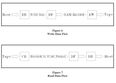
Write. The first block of data is accepted from the DB card across an 8-bit bus and
is stored in RAM. While a second block of data is transferred to the DF card, the first block is encoded into the format in which it will be written to tape. While a third block of data is being transferred to the DF card, the second block is encoded and the first block is serially transferred to the RW card to be written to tape.
Figure 6 indicates data flow during a write operation.
This sequence repeats until the eighth block of data is transferred to the RW card, at which time the sequence starts over with the first block of data for the following track (starting with the transfer and encoding of three blocks).
Encoding During Write. When data is transferred from the DB card to the DF card,
the data is in an 8-bit format. Prior to its transfer to tape, the data is encoded into a 10-bit run-length-limit format. Additionally, the following information is also encoded into the block of data:
■ 96 bytes of synchronization fields ■ 48 bytes of segment numbers ■ 400 bytes of Reed/Solomon ECC ■ 14 bytes of block header information
■ Two bytes of Cyclic Redundancy Check (CRC)
■ Pad bytes and pad blocks inserted where necessary
Encoding details are described in the ANSI Helical-Scan Digital Computer 8mm
Tape Cartridge Format Standard (X3B5/89-136).
Read. Serial data is transferred to the DF card from the CD card. The data is then
decoded from the run-length-limit encoded format (10 bits) into an 8-bit byte data format. When the last byte of a physical block (1,024 bytes) is transferred to the DF card, error correction starts on that block while a second physical block of data is transferred to the DF card from the CD card.
Figure 6 indicates data flow during a write operation. Figure 7 indicates data flow during a read operation.
6.4. Microprocessor (MX) Card
The Microprocessor (MX) card maintains most of the on-board intelligence. The main program logic resides in an 8052 microprocessor. The MX card is responsible for: 1) scheduling operations, 2) handling external interrupts, 3) idle loop manage-ment, and 4) data transfer and formatting operations.
A detailed discussion of the format is available in the ANSI Helical-Scan Digital
Computer 8mm Tape Cartridge Format Standard (X3B5/89-136).
The MX card initiates all operations to the command registers.
[image:26.612.56.538.130.474.2]The MX card also controls the serial interface, which is used for diagnostics and troubleshooting. Diagnostics are initiated by the MX card for the entire system, excluding the servo system and mechanical components.
Figure 6 Write Data Flow
Default power-on conditions (such as memory testing, parity checking, and odd or even byte disconnect) are set with either the switches or jumpers located on this card. These switches and jumpers are interpreted by the MX card and are used during command processing. The issuance of a Mode Select command by the host overrides the power-on defaults until another Mode Select command is issued or the EXB-8200 is powered off and then on again.
Eight kilobytes of RAM are maintained by the MX card. The RAM is used during read back operations. This area is a “scratch pad” for the MX microprocessor for table manipulation and temporary storage.
Header Information. Each block of user data has an associated 14 bytes of header
information that the MX card adds to the data before it is written to tape.
Reset Conditions. The MX microprocessor encodes and processes power-up resets
and SCSI bus and device resets.
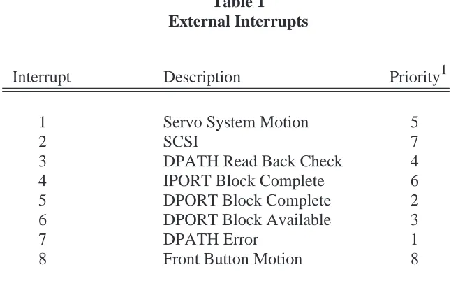
External Interrupts. Eight types of external interrupts can be received and
proc-essed by the MX processor. These interrupts and their values are listed in the following table.
Interrupt Description Priority1
1 Servo System Motion 5
2 SCSI 7
3 DPATH Read Back Check 4
4 IPORT Block Complete 6
5 DPORT Block Complete 2
6 DPORT Block Available 3
7 DPATH Error 1
[image:27.612.146.469.404.610.2]8 Front Button Motion 8
Table 1 External Interrupts
6.5. Data Buffer (DB) Card
The Data Buffer (DB) card provides two main functions: 1) the on-board SCSI Module and 2) buffer memory for asynchronous data transfers to and from the EXB-8200. Overall functional control is maintained by the microprocessor on the MX card. There are three main sections to the DB card: 1) a SCSI Module, 2) a custom LSI module, and 3) buffer memory. These three sections are described below.
SCSI Module. A bi-directional device that provides the SCSI bus protocol functions
and also transfers data to and from the IPORT of the LSI Module. The SCSI Module provides SCSI protocol functionality. The SCSI chip on the DB card performs bus arbitration, command status posting, SCSI bus disconnect/reconnect, and bus parity checking. It provides asynchronous data transfers, to and from the EXB-8200 and host, across the SCSI 8-bit (plus parity) data bus.
The SCSI Module consists of the Western Digital WD33C93A chip (SCSI chip), 50-pin connector, and single-ended SCSI bus terminators for use when applicable. Functionally, the SCSI Module has two ports: 1) to the SCSI bus and 2) to the IPORT of the LSI Module.
When the EXB-8200 is configured for differential SCSI bus applications, the DS card replaces the DB card. The DS card is functionally identical to the DB card except that it has the appropriate drivers/receivers to interface with a differential SCSI bus. A differential terminator, external to the 8200, must be used when the EXB-8200 is used to terminate a differential SCSI bus. The differential terminator is not supplied by EXABYTE.
Control of the SCSI Module functions is maintained by the microprocessor on the MX card. The control path flows from the MX card through the LSI Module to the SCSI Module. All SCSI commands received by the SCSI Module are passed on to the MX card, which determines whether the command is legal and appropriate. If a SCSI disconnect or reconnect operation is deemed necessary, the MX card directs the SCSI Module to perform the function.
Custom LSI Module. A bi-directional device that provides buffer management, data
Dynamic Buffer Memory. A temporary storage device for data being written to or
read from tape. Provides 256 kilobytes x 1 dynamic RAM implemented in a 256-kilobyte x 9-bit circular buffer configuration. All data transfers involve storing data in buffer memory for some period of time. That period of time is dependent on the selectable Motion and Reconnect Threshold values and whether the data is being transferred in the user-selectable Buffered or Non-Buffered Mode.
The custom LSI Module uses buffer memory management to most efficiently use the capabilities of the EXB-8200. The Motion and Reconnect Threshold values are used in managing the buffer.
6.6. Servo (SV) Card
The Servo (SV) card controls all the mechanical functions of the tape deck. Servo commands are initiated by the MX card, but the execution is controlled by the SV microprocessor (HD6303X). The servo control software is stored in a 128-kilobyte EPROM. A custom LSI servo gate array interfaces the SV microprocessor and the mechanical drive circuitry.
Additional functions that the SV card provides are as follows:
■ Serves as mother board for the five other cards in the EXB-8200 (see Figure 3
for the location and names of the five cards).
■ Senses 184 KHz frequency zones on tape which are used to indicate Logical
Beginning of Tape (LBOT), ATMs, and track-embedded servo.
■ Adjusts capstan tape velocity based on the track-embedded servo information.
■ Controls the cartridge loading and unloading and automatic threading and unthreading of tape into the tape path.
■ Displays the drive’s readiness and transfer activity via LEDs.
■ Provides the power interface for the EXB-8200.
■ Provides a serial port interface used for diagnostic purposes.
Hardware Interface. In the EXB-8200, the controlling processor is located on the
The interface consists of two 8-bit registers and two interrupt flags, as follows:
■ The first register is used to transfer commands from the MX card to the SV card.
■ The second register is used to transfer status from the SV card to the MX card.
■ The Servo interrupt flag is set whenever the servo writes to the second register. This flag is used to notify the MX card of pending status.
■ An Interrupt flag is set whenever the unload switch on the front panel is pressed. Once set, both of these flags remain set until cleared by the MX card.
Software Interface. The software interface between the SV card and the MX card
is a high-level, command-oriented system. In general, the MX card writes a com-mand byte to a register. The SV card receives the comcom-mand and executes the requested function. The SV card indicates the completion of the command by writing status to the second register and interrupting the MX card. The MX card then clears the interrupt and gathers the status information from the completed servo command. A large number of servo commands are designed to implement specific functions and complex motions specific to the tape transport mechanism and the tape format. There are 16 servo status bytes that are available to the MX card via the software interface. During normal error-free operation, only two of these status bytes are used.
Servo Error Handler. The motion control system is based on a SV microprocessor,
which has the ability to detect and report error conditions to the MX card. The errors can be detected in power-up self-tests, dedicated diagnostics, and in real time during actual operation. Whenever an error condition is detected by the servo system microprocessor, control is immediately passed to the error handler. The error handler has two primary functions: 1) to safely terminate all motion functions without damaging the tape or any of the system components, and 2) to communicate the error condition to the MX card. The errors are reported through the hardware interface registers mentioned previously.
Failure Conditions. The servo system is designed to detect failure conditions that
may exist in the tape deck and in the servo electronics. Failures can be detected either during power-on self-test, after a reset, and during real-time operation.
Servo System Components. The servo system components are listed below.
■ Servo card (described above)
■ Exadeck – Manufactured exclusively for EXABYTE by Sony. It is a hybrid version of the standard Sony 8mm video cassette deck.
■ The drum assembly, which consists of: ❏ Three heads (each .025 mm in width):
– Write/read head – Read back check head – Servo read head
❏ Rotary transformer modified for low crosstalk between servo write and read back check operations
❏ Vertical head alignments customized for a -10 degree azimuth angle, .031 mm track pitch
■ Erase head ■ Motors:
❏ Capstan: Direct drive, brushless DC motor used to move tape
❏ Drum: Direct drive, brushless DC motor used to rotate drum
❏ Reel: Idler gear drive, brushless DC motor used to drive the supply and
takeup reels
❏ Mode control: Worm gear drive, brush DC motor used to drive the mode
control bar
❏ Load control: Gear drive, brush DC motor used to drive the load ring
■ Rotational sensors/tachometers: ❏ Capstan tachometer
❏ Drum tachometer ❏ Drum sync
❏ Supply reel tachometer ❏ Takeup reel tachometer
❏ Capstan motor commutation
■ Other sensors:
❏ Mode state ❏ Load state
❏ Door closed, Write Protect, Metal Particle/Metal Evaporated, 120-minute tape
7. Functional Description
The EXB-8200 functions are based on SCSI-1 commands; therefore, this functional description of the EXB-8200 adheres to SCSI-1 protocol.
7.1. Write
When a Write command is issued, the following sequence of events occurs:
1. A Write command is issued by the host across the SCSI bus to the EXB-8200 SCSI chip, which resides on the DB card.
2. The command is transferred from the SCSI Module to the microprocessor on the MX card via the IPORT and Software Interface port of the LSI Module. 3. From the command information, the microprocessor generates block header
information and puts it into IPORT registers on the LSI Module.
4. Data is transferred from the host to the EXB-8200 and is passed from the SCSI Module to the LSI Module via the IPORT.
5. When 1,024 bytes (one physical block) of data has been transferred into the LSI Module, the data is written to the buffer along with its associated block header information that was stored in the IPORT registers.
6. More data is transferred until the amount of data in the buffer exceeds the selected Motion Threshold value. Then the head drum spins up, and all data and header information is read out of the buffer and transferred to the DF card (via the DPORT of the LSI Module) to be written to tape.
7. The buffer eventually fills with data if the transfer rate from host to buffer is greater than 246 kilobytes per second. At that point, the microprocessor com-mands the SCSI Module on the DB card to perform a SCSI disconnect sequence that results in the halting of data transfers from the host to the EXB-8200. 8. Data continues to be transferred from the buffer to tape until the amount of
7.2. Read Back Check
Every block of data stored in the buffer has corresponding Block ID and Retry Count values in its header block. After a block of data is written to tape, the following sequence of events occurs in the read back check process:
1. Using CRC, the read back check head reads the block to check for accuracy. 2. If a block of data is determined to be inaccurate, that block is scheduled for a
rewrite to tape 11 blocks later. The block is identified by its Block ID. The Retry Count is the number of attempts taken to write that block of data to tape.
7.3. Rewrite
Every block of data stored in the buffer has corresponding Block ID and Retry Count values in its header block. If, during the read back check process, a block of data is determined to be inaccurate and scheduled for a rewrite, the following occurs: 1. An attempt is made to rewrite that block to tape 11 physical blocks later. The
Block ID value is used to fetch the proper block from the buffer for rewriting. 2. The Retry Count value for that block is incremented. The Retry Count is the
number of attempts taken to write data in that block to tape.
7.4. Read
When a Read command is issued, the following sequence of events occurs:
1. A Read command issued by the host is received by the SCSI Module and transferred to the microprocessor on the MX card via the IPORT and the Software Interface port of the LSI Module.
2. The microprocessor notifies the LSI Module to route data from the DPORT to the buffer, then from the buffer to the IPORT.
3. Data blocks and their corresponding headers, having gone through the ECC process on the DF card, arrive at the DPORT of the LSI Module and are placed in the buffer.
4. From the buffer, the host-requested data is transferred through the IPORT of the LSI Module to the SCSI Module, where it is transferred to the host.
A minimum of 256 kilobytes of data are read from tape for any Read command. For example, a 10-kilobyte Read request by the host results in a read of 10 kilobytes plus the next 246 kilobytes of data. Only the requested 10 kilobytes of data are transferred to the host.
5. During a read from tape, if the buffer fills with data, transfers from tape to buffer are halted until the amount of available data space in the buffer is greater than the Motion Threshold value. When this situation occurs, data transfers from tape to buffer are resumed.
6. If a block of data is not buffered as a result of ECC rejection, the result is a “buffer hole.” That particular block is expected to have been rewritten to tape 11 blocks later.
When a rewritten block is encountered during a read operation, the Block ID value in the header is used to put that block in the proper location in the buffer (i.e, the proper buffer hole).
7. The transfer of data to the buffer is halted when the block to be transferred is equal to the buffer hole.