doi:10.4236/jsea.2011.44023 Published Online April 2011 (http://www.SciRP.org/journal/jsea)
End to End Development Engineering
Abdelgaffar Hamed
1, Robert M. Colomb
21College of Computer Science and Information Technology, Sudan University of Science and Technology, Khartoum, Sudan; 2
Faculty of Computer Science and Information Systems, Universiti Technologi Malaysia, Skudai, Malaysia. Email: [email protected], [email protected]
Received February 22nd, 2011; revised March 10th, 2011; accepted March 13th, 2011.
ABSTRACT
Raising software abstraction and re-use levels are key success factors for producing quality software products. Model- driven architecture (MDA) is an OMG initiative following this trend by mapping a conceptual model of application specified in platform independent model (PIM), to one or more platform specific models (PSM) automatically. Because there is little previous work tackling the development problem from specification through to implementation, this paper proposes End to End Development engineering (E2EDE) method using MDA methodology. E2EDE is intended to fill the mapping gap between PIM and PSM in MDA. The notion of variability is utilized from software product line and used to model design decisions in PSM. PIM is equipped with Nonfunctional requirements which borrowed from Design pattern to inform design decisions; thereby guiding the mapping process. In addition we have developed a strategic PSM for messaging systems can be configured to produce different applications such as the helpdesk system which is used as a case study.
Keywords: End to End Engineering, MDA, Metamodeling, Domain Engineering
1. Introduction
The complexity of producing large-scale software systems is increasing due to the increased complexity of require- ments. Technologies are volatile for many reasons but enhancing the quality of services is among clear reasons justified by software providers. For example, java plat- form versions and Google chrome browser has adopted new browsers technology. The functionality of browsers is already crafted (i.e. Mozilla) but putting it into a new fashion is because of security, performance, reliability, and etc. On other hand, service-based system (SOA) has emerged as new engineering discipline encourages orga- nizations to integrate their systems in a seamless manner. These highlight questions like 1) How to extend the tra- ditional methods (Code-based) in a longlived architec-ture to deliver these new businesses?2) how to provide an effective integration with legacy systems?3) If a deci- sion is made to change technology (acquiring new qual- ity such as security and performance) is the design easily adaptable?The trend now is proposing model-based en- gineering approach which means separating concerns where software development is driven by a family of high level languages [1]. To this end abstraction level is raised above 3GLs which increases re-using
theme and put software artifact into a situation of core asset. More importantly formalizing of these artifacts (i.e.
metamodels) leads to realize the benefit of high degree of automation. This means a machinery of specification (i.e.
UML), synchronization and management of these models are essential. Thus, software not a program became like an information system itself. Thereby the crafting of code is becoming a manufacturing process not a personal skill. Model Driven Architecture (MDA) is a new software development method following that trend. It raises ab- straction level and maximizes re-use. Using MDA, we will be able to work with software artifacts as assets which from the software engineering perspective is a ma- jor success factor for reliable and fast development. The philosophy of MDA is to do more investment on soft- ware artifacts (models) to increase their efficiency, lead- ing to systematic and more powerful mechanisms for so- ftware re-use.
MDA is an aspect of the more general discipline of software reuse. The synergistic relationship among MDA and the longer-established areas of Design pattern and software product line engineering (SPL) [2] has been stu- died as part of the present research [3,4].
standing research aim, and because of the mapping gap from PIM to PSM, E2EDE has emerged. Most of previ- ous work in MDA has been on infrastructure and compo- nents. Therefore the major question in this paper is how to write a program in MDA?
End to End development engineering (E2EDE) is a new trend to software engineering, proposed to answer that question, which uses MDA methodology and explo- its some experience from Software Product Line (SPL) and lessons from Design Pattern (e.g. nonfunctional re- quirements) to automate the development from specifica- tion through to implementation. In doing so, we need to investigate the relationships among MDA, SPL, and de- sign pattern and how MDA can fit on them. Therefore the contributions of the paper are the following:
1) We present E2EDE to automate the mapping pro- cess as realization to MDA which is intended to produce products without entirely writing code.
2) We discuss the relationship between MDA, SPL, and design pattern and how MDA can fit in the both lon- ger established re-using approaches.
3) We share some lessons learned and challenges of MDA software engineering in practice.
Domain engineering is the key concept utilized from SPL which realizes breeding of a number of products that have similarity and some sort of variability in features. Design pattern in the history of software engineering has concerned with linking the design with nonfunctional requirements. Therefore, Nonfunctional requirements is borrowed as a concept.
The paper is organized as follows: Section 2 describes MDA as a major method used in E2EDE. In Section 3 we explain the problem through example of mappings from QVT specification. The proposed E2EDE methodology is discussed at Section 4. The concepts of E2EDE are validated by case study at Section 5. Sections 6 and 7 describe the relationship among MDA, Design Pattern and SPL. Section 8 draws on the principle of MDA and shows a case of strategic PSM. In Sections 9 and 10 we discuss MDA and E2EDE implementation aspects re- spectively. In Section 11 the realistic value of our ap- proach with existing platforms is investigated. A conclu- sion is presented in Section 12.
2. Model Driven Architecture (MDA)
MDA is a new development paradigm initiated by the OMG aimed at software development driven by model [1]. In this case, a Platform Independent Model (PIM) is used to specify application behavior or logic by using MOF or a MOF-complaint modeling language [3]. This step re- presents a problem space in an application-oriented pers- pective. A Platform Specific Model (PSM) is used to rea- lize a PIM. It represents a solution space from an imple-
mentation-oriented point of view. Therefore, a transfor- mation from the problem space to the solution space is required. The automation of this process is the ultimate goal of MDA. Thereby, when we need to change the ap- plication, changes will be in only one part (PIM) without affecting implementation technologies (PSM). Converse- ly, when the platform such as SQL Server is changed re- targeting a new platform for example new version (has enhanced feature), we need only to select the appropriate PSM and then regenerate the code not only without mod- ifying PIM but also this time re-using most of the trans- formation. Productivity becomes higher and cost is redu- ced due to the increased reuse of models. In addition, maintenance becomes cheaper. It is worthwhile to obser- ve here that MDA is working with models as assets that can be reused once the initial investment is made. MDA depends on a well established code-base.
2.1. MDA Transformation Process
The transformation from PIM to PSM is done by a map- ing function, which is a collection of mapping rules. In this case some or all of the content of the target model is defined. It is expected that when MDA automates this process, development efficiency and portability would significantly increase. In addition, the mapping function can be repeated many times (re-used) for different appli- cations using the same PIM and PSM metamodels. MDA also helps avoid risks of swamping the application with implementation detail which causes model divergence [5]. The steps of designing a system is to create a concept- tual model by designers for application requirements and developing another implementation model to map the fir- st into the second. But this might involve many sub acti- vities. However, we can divide MDA into two major pro- cesses [1]:
1) Model to Model mappings
The mapping in this stage does not consider any speci- fic characteristics or special cases that apply to technolo- gy or platform (called M2M). The result of this phase is still high level model but for code (PSM instances).
2) Bringing in a Particular Platform
The goal of this mapping (sometimes called M2T) is tailoring the conceptual model to specific technology. Different platforms have different features and constrain- ts so step 1 will be refined to conform to features of one of the selected platform. The result in this phase is expec- ted to be context dependant code expressed in a platform concrete syntax. In fact, we intended to use the word
bringing to denote applying the principle of MDA in de-veloping standard PSM.
2.2. Metamodeling
UML data model (i.e. class diagram) is called a meta- model, which has concept like a class. A particular design in a design language is called model instance like student class in the student record system. This model instance can be visualized by using UML model instance (i.e. ob- ject diagram) but also MOF has similar model instances metamodel. A metamodel defines a schema for database called a repository. The population of this repository is the model instance. Formation rules of the metamodel are expressed as constraint on the repository [6]. A meta- model represents syntax of a modeling language. If the metamodel tells the designer how to create a model in- stance, it is said to be concrete syntax [6]. If it does not, it is said to be abstract syntax. Therefore, sometimes rendering conventions augmented with abstract syntax to generate concert syntax like MOF instance specification [7].
Model-based design that relies on a repository (tables or data structure) for storing a complex object (design), is the key art behind the MDA approach. For example QVT mappings are specified as patterns on schemas, or meta- model [8]. In this way, information contained in the mo- dels is separated from the algorithms defining tool be- havior, instead of being hard-coded into a tool. The algo-rithmic part of tool communicates with models via an abstract program interface (API), which affords the facil-ity to create, modify and access the information in models [9]. Further, MDA tools can transform model instances into various forms. For example, the mappings from PIM to PSM takes PIM metamodel instances from the instan- ce repository and turns it into corresponding instances updating the target repository, moving from problem spa- ce to solution space.
This mapping activity is done using standard language independent of the source and target. The metamodel of the mapping from end to another end can also be re-used as an asset.
2.3. Query, Views, and Transformations (QVT)
Two kinds of transformation are recognized in MDA community:
• Horizontal, that does not change the abstraction level, for example from PIM to PIM which is used when a model is enhanced, filtered or specialized (mapping from analysis to design),
• Vertical, that changes the abstraction level, for ex- ample projection to the execution infrastructure. Four types of these transformations are categorized in [10].
There are tools to specify such mappings, such as query-view-transform QVT [8]. QVT is an OMG standard which helps us to specify rules for the transformation function. QVT uses the concept of predicate (expression
evaluated to true or false) and pattern (set of expressions) in much similar way as prolog programming language.
The intended scenario of writing a program using MDA will be demonstrated first by an example then below in our case study where the mapping task is the major activ- ity. Generally the application development is a process involves many transformations so vertical and horizontal or combination of them might be used.
3. MDA Example and Mapping Problem
We will use the QVT specification [8] example of object to relational mappings in order to understand where the problem is in this context. For sake of simplicity we fo- cus on part of the mappings between PIM (object model) and PSM (relational model). This example shows the mappings take place between simplified UML2 metamo- del in Figure 1, the PIM, and the PSM in Figure 2.
The mapping between conceptual models and relatio- nal schema is well established in the database. The gen- eral idea is that classes map to tables, packages map to schemas, attributes to columns, and associations to for- eign keys. We will discuss part of this mapping informal- ly then we will show simple QVT rules for that.
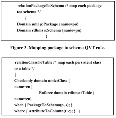
In Figures 3 and 4 examples we have a relation (use to specify rules of mapping source to target) named Pac- kageToSchema, and ClassToTable. Both have two do- mains that will match elements in uml (our PIM) and rdbms (our PSM).The relation ClassToTable specifies the map of a class which has attribute name with value equal the variable “cn”. All classes instances in uml repository will populate this variable one by one. For example if the model instance of our PIM is student record system, these will be person, lecturer, student, etc (M1). If the precon- dition is satisfied by this way the enforce clause is very similar to a checkonly clause. If there is an instance in the rdbms repository satisfying the pattern expression, then the enforce clause behaves as a predicate, with the value true. If no such instance exists, then the QVT en- gine will create one.
The mapping takes structural patterns in the M1 PIM model (problem domain) instance into in some cases quite different structural patterns in the M1 PSM model (implementation domain). The patterns are described in the M2 metamodel. Thereby that mapping is grasped as a part of the process of specifying and implementing the system. This process in most traditional software engi- neering methods is done manually. The ultimate goal of mapping is having a way to be able relate M0 instances of the PIM to M0 instances of the PSM. But the standard- document of MDA [1] does not specify how to do that.
Figure 1. Simplified UML2 metamodel from QVT [8].
Figure 2. Simplified relational database model from QVT specification [8].
create and destroy methods for objects and links are spe- cified as MOF standard operations for creating and de- leting dynamic objects [7]. So the objects created and destroyed by these methods are of kind M1 objects for M2 metaclasses. By this way an instance model will be created for M2 metamodel elements similar like having student, lecturer, and course, etc., instances. UML stan- dard also specifies methods for creating instance model for M1 objects which are M0.Hence since like the in- stance model of record system is UML instance model then it should be able to create m0 objects using UML model instance inherited capabilities: create and destroy
of objects and links.
The intended scenario for mapping is that an applica- tion using application terms have a facility to create ob- jects which is PIM instance model. On other hand the implementation model that is PSM creates objects corre- sponding to that objects using PSM concepts and terms which represents a design vocabulary. To this end still in the MDA development (i.e. using MDA to solve prob- lems) the question is how to do this process which re- quires finding concrete technical mapping methods.
[image:4.595.60.285.439.693.2]Figure 3. Mapping package to schema QVT rule.
Figure 4. Mapping class to table QVT rule.
writing code. Here the task for developer/modeler is a function of specification where application requirements, implementation and mapping metamodels are presented using design languages such as UML/MOF and mapping language such as QVT. In this case mapping and syn- chronization among models are performed by toolset.
4. Proposed E2EDE Design &
Implementation
This section demonstrates key points of E2EDE and ex- plores most important aspects that should be addressed.
4.1. Introduction
End to End development engineering (E2EDE) is a novel paradigm intended to automate software development from the specification end (i.e. object model) to the im- plementation end (i.e. relational model) using the MDA approach. The central issue is filling the mapping gap between PIM and PSM in MDA.
Theoretically E2EDE is inspired from an investigation of the synergistic relationship among MDA, SPL, and de- sign patterns as we will see in Sections 6 and 7.The ratio- nale behind establishing this relationship was from litera- ture SPL and design patterns have long history of re-use software development. So they are longer established re- use methods. MDA is a more recent stream of re-use. E2EDE engineering is going to exploit this relationship to achieve its mapping goal. The key concept in SPL is variability which gives customization or configuration options. Variant feature is a place in the software artifact can be populated by at least one variant at a time from a
set of variant. For example, if color is variant feature then Red is one variant. We conceive design decisions as variation points and the design choices as variants popu- lating these points. This comes from the observation that PSM as a design artifact has different structures most properly lead to different architectural qualities. Therefore, to model design decisions we need to represent variabil- ity explicitly in the PSM. The study of the design pattern approach highlights the importance of the relationship between design and requirements, specifically nonfunc- tional requirements, which is proposed to be modeled in the PIM. Still there is a research gap in these areas on how to map nonfunctional requirements with design de- cisions systematically. The problem has been looked at from one dimension, for example SPL has concerned only with variability without considering NFR such as [2,3,11, 12] while design pattern has recognized the impact of NFR dimension without variability in an explicit way [13-15].
However, the benefit here is PSM construction could be automated effectively because of consideration of de- sign quality and management of single PSM. Hence, do- cumenting variability in architecture and modeling non- functional requirements explicitly will become major ac- tivities during the development process. This section de- monstrates key issues arising when we tackle E2EDE. Further, these issues have been applied to a selected case study to evaluate the possibility of the proposed enginee- ring approach.
The ultimate goal of E2EDE is to provide a method of generating a solution from one specific source to a spe- cific target like for example, from object-model to rela- tional model. The advantages of E2EDE are reflected in the modeling support for the concepts in the domain and the ability to do more than general-purpose languages do, in addition to reduction of cost.
4.2. The Steps of E2EDE Process
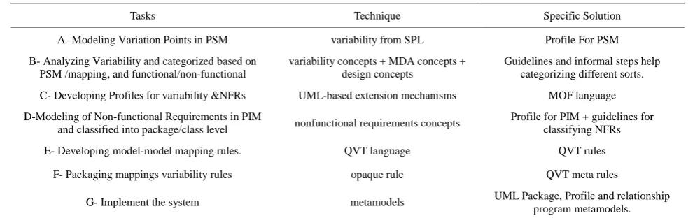
In this section we will see the main steps of E2EDE. It will be detailed step by step and finally summarized as shown in Table 1.
Table 1. The steps of E2EDE process.
Tasks Technique Specific Solution
A- Modeling Variation Points in PSM variability from SPL Profile For PSM
B- Analyzing Variability and categorized based on PSM /mapping, and functional/non-functional
variability concepts + MDA concepts + design concepts
Guidelines and informal steps help categorizing different sorts.
C- Developing Profiles for variability &NFRs UML-based extension mechanisms MOF language
D-Modeling of Non-functional Requirements in PIM
and classified into package/class level nonfunctional requirements concepts
Profile for PIM + guidelines for classifying NFRs
E- Developing model-model mapping rules. QVT language QVT rules
F- Packaging mappings variability rules opaque rule QVT meta rules
G- Implement the system metamodels UML Package, Profile and relationship program metamodels.
periences are utilized to document design decision vari- ants explicitly in the architecture. For example we will see in Section 5 two types of connection: Topic (indirect) and Queue (direct) for a messaging system. The variability difference is that in topic multiple subscribers receive a message while in queue only one subscriber is allowed to receive. This variability can be modeled as two different structures at PSM or formally as variants populating the
connectionType variation point.
Since standard UML does not have a variability conce- pt, modeling variability in a PSM we need to use a profile to allow us to specify the variability ontology. A profile is a special domain language used as an extension mechan-ism to UML model elements while keeping their syntax and semantic intact.Proposed metamodels and profiles in the literature such as [2,12]can allow an architect to iden- tify specific variation points, constraints and dependen- cies that indicate different relationships between varia- tion points (VP) and variants (V), VP and VP, etc.
Because we are using design model (i.e. class diagram) the proposed profile here is different from these because there is no need for dependency and constraints concepts. They are built-in mechanisms whose semantics is speci- fied with the mapping process and NFRs. Also, there is no need for open and closed concepts which gives the ability to add new variant or variation points because all are closed in this situation (MDA works above 3 GLs).
Therefore, developing a suitable variability MOF-pro- file is an essential part for the solution presented by E2EDE.In fact there are alternative ways to model vari- ability and nonfunctional requirements concepts using a profile. The method we have chosen will help produce a working system.
The variability ontology needed includes the concepts
variant indicated by <<V>> stereotype, variation point
indicated by <<VP>>, and an ID tag attribute to identify each VP.
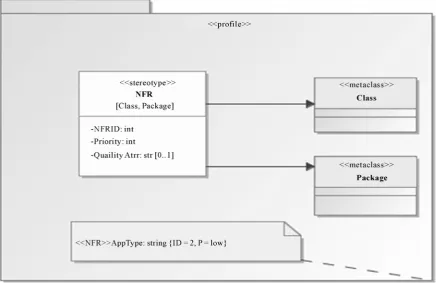
In Figure 5 the UML metaclass class is extended to
represent variant and variation point. A tagged value ex- tension mechanism is used to model identifier and type meta-attributes. Tagged values are additional meta-att- ributes assigned to a stereotype, specified as name-value pairs. They have a name and a type and can be used to attach arbitrary information to model elements.For in- stance, if we need to model ConnectionType (the two kinds of connections in messaging system) variation point we use the stereotype <<VP>> and for its variants Queue and Topic we use two <<V>> at class level. Then the tag for ConnectionType will be VPID =1and default
can take the value Direct. The effect tag of variant speci- fies design decision consequences like resource consump- tion.
4.2.2. Variability Analysis (Task B)
Figure 5. Variability MOF-profiles.
this deficiency four options are suggested for this map- ping in the standard database literature [17].
Generally these options can be classified into single- relation and multiple-relation approaches named SR and MR respectively. In the SR approach a table for super- class attributes will be created with subclass attributes included as optional while in MR approach table for each subclass will be created. Two implementation techniques are available for both. SR can be implemented by intro- ducing one type attribute indicating the subclass to which each tuple belongs (null values will introduced), or multi- ple boolean type attributes can be used (allowing over- lapping subclasses). MR has as one option with super class attributes duplicated in each subclass table and ano- ther option to share a key among superclass and subclass tables.
For example, the option of one table for the superclass with subclass attributes included as optional is a good de- sign in terms of performance for SQL navigation, at a cost of increased table space and increased integrity checking.
4.2.3. Modeling of Non-Functional Requirements (Task D)
The E2EDE methodology considers NFRs as first class objects which allow a PIM metamodel to be more infor- mative. The separation of concerns (i.e. PIM-PSM) of MDA effectively supports their representation.
Functional requirements are functions that the devel-
oped software must be capable of performing, while non- functional requirements (NFRs) inform the design choi- ces as to how functional requirements are going to be realized in software products [16]. There is no one agreed definition because of the extremely diverse nature of NFR. In fact, practices like in design pattern shows a single NFR can have different semantic interpretations (impact on implementation) within the same application. These can be called impact factors. For example in our case stu- dy, connection types, session types, and message types are impact factors affecting performance positively or nega- tively. There is confusion in term usage where a term so- metimes refers to the nature of the requirement and so- metimes refers to the design decisions. We will be using the term NFR to denote the nature of the requirement so a PIM metamodel is the place where we can define spe- cific NFR types.
tributes negatively or positively to one NFR. Preliminary results show diversity in terminology and orientation [4]. In addition, there are dependency relationship among non-functional requirements. For example, in some cases maintainability requires portability. More importantly conflicts are found such as between performance and re- liability as shown in our case study below.
The field of nonfunctional requirements as a compo- nent in requirements engineering is less developed than functional requirements[19], so there are only a few con- tributions such as [14,20,21].We are going to follow a simple approach that would be compatible with E2EDE. For example, Zuh and Ian [22] proposed a generic UML NFR Profile, but it is not suitable to work under MDA because the assumption was to treat NFR and design de- cision in one place. These are different (separate abstract- tion levels) according to E2EDE’s principles. The 6-ele- ments framework from SEI [21] follows a scenario-based approach that presents a good way to resolve the over- lapping problem between NFRs. Our approach simply prioritizes NFRs to judge on design decisions, promoting automation.
Since the types of NFRs differ greatly among classes of application, a NFR Profile is needed as a domain spe- cific language to allow system architecture to specify NFRs easily in a PIM metamodel. According to investi- gation in this track we have seen there is a need to priori-
[image:8.595.80.517.423.706.2]tize NFRs so the toolset can tradeoff between NFRs or resolve conflicts. Most of the current contribution to NFR considers the human factor and does not take account of tool support. For example Zhu and Ian [22] proposed for the relationship between design decision and NFR: sup- port, break, help and hurt. Daniel and Eric [14] follow the same trend. In order to reach our goal we need to identity NFRs so the identifier concept is used to discriminate NFR instances. The 6-elements framework suggested by [21] could be a useful tool for Non-functional analysis at earlier development phases.
Figure 6 shows the elements of the NFR profile (Task C) used by an architect to specify NFRs which is spe- cializing a metaclass class with two tag attributes. Below in the anchor is an example of an instance model. It also shows NFRs can be at Package level, which represents global NFRs such as Application Type, while delivery mode is at class level. It also shows that NFRs can act as
Packagelevel, which represents global NFRs such as Ap- plication Type, while delivery mode is at class level.
4.2.4. Transformation of informative PIM to PSM (Task E)
The notion of transformation is hardly a new concept in software engineering. Traditionally, most software engi- neering work is conceived of as mapping, like the trans- formation from software specification to software design.
But what makes MDA different is considering mappings as first class objects in the effort to formalize this process by using standard languages such as QVT where mapping is from one metamodel to another metamodel. This appr- oach is a prerequisite for the automation that MDA is seeking to achieve.
The key concept of MDA mapping is to resolve a stru- cture pattern instance from PIM into a PSM correspond- ing structure pattern(s) instance. For example, in case of mapping from object model (PIM) to the relational mod-el (PSM), a class instance will map to a table instance.
Our work proposes NFRs as major design drivers fee- ding the mapping process. This feature facilitates the ma- pping task where it becomes easier to select the corre- sponding PSM structure. NFRs make the difference be- tween two PSM configurations. For instance, as we will see later there are two types of messages, persistent and nonpersistent, in the messaging system. If performance impact factor(s) are most important, the nonpersistent variant is suitable while if reliability is a design issue, the persistent variant is the best option. The former architect- ture will expose performance quality while the latter will expose reliability based on the additional computation the application needs to maintain the message storing process.
4.2.5. Mappings of Class Operations
The class structure in UML includes methods or behavior. Because maintaining different views in one model is com-plex, UML supports capturing dynamic behavior of the system separately by a set of behavioral diagrams such as the activity diagram. This subsection is about highlighting mapping problem from PIM instances of the process model to PSM instances of its process model. In this case a metamodel does not have user-defined opera- tions, the MOF specification has defined default methods: create object, destroy object, and create link in each MOF metaclass [7]. Firstly, these methods are abstract methods. Secondly, mappings of structural patterns are somehow straightforward but the relationship between PIM be-have- ioral model and PSM behavior is nonlinear. So when mappings for example occurred for attributes which are going to be columns in the relational model, there might be a set of corresponding operations (1 to M relationship) in the PSM behavioral metamodel for a corresponding class’ methods in PIM behavioral model. However, there is no uniquely determined method to do that. Recent attempt for example in this case was sug- gested by [6], one possible MDA program written for medium-sized problem involving organizing a swimming meet according to FINA rules (insert and update native call) utilizing OCL capability to construct SQL PSM.
However, we can use the hierarchy structure of UML activity diagram to show the implementation of PIM me-
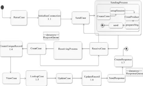
thods in PSM as workflow as in our case study in Figure 7: Sendcase mapped to SendingProcess where it is ex- tended into five operations as described in 5.3.
We notice here future work is needed to find a method that realizes the operations mapping so we can see how to incorporate variability and NFR concepts.
Generally the tasks comprise E2EDE process are shown in Table 1.
5. Case Study
A set of applications has been analyzed to produce the PSM architecture used by this case study as an imple- mentation end. This family of products which are men- tioned in Table 2 has exposed commonality in most as- pects under messaging system domain. This analysis step is in line with the principle of domain engineering where at least three products should expose commonalities to justify the investment in core asset architecture [23]. A Help desk system is one example from this set of produ- cts which is a major component in most current business web-based systems. The idea is to allow a user to raise a case for some aspect which needs a reply from some or- ganization web site party. An employee should consult through the same web site a list of cases or a specific case that has been presented as a request in order to update it. Then the update is sent back to user, who may be offline, as response. A broker is an intermediate module used to exchange messages between the system and users. Users contacting the system are durable customers. The non- functional requirement for system performance is higher than reliability.
5.1. The Problem Specification
The helpdesk software system is needed to service cus- tomer(s) and employee(s) at the same time. A customer will be required to insert identification information such as user name and password after registration—both of which will be sent for validation to the web site system which is located remotely somewhere on the internet. The customer as well as the employee will then be able to perform one or more operations.
The helpdesk must be able to provide the following services to the customer:
1)A customer must be able to login using his account information.
2)A customer must be able to submit a case to any employee linked to organization, by writing a text messa- ge and submitting it to a broker.
3)A customer must be able to view their case history (feedback), status, and details.
Figure 7. Behavioral mappings activity for helpdesk PIM to messaging system PSM. Table 2. Configuration for a set of products from PSM metamodel with profile.
Appliction domains NFR Profile Priority Variation point(Design Decisions)
<Message,connection,session,Ack>
1-Email System
App-size = normal Iscritical = yes Delivery = notUrgent
P1 P2+P3>P1
P3
<persistence,queue,transacted, AutoAck>
2-Chat
App-size = normal Iscritical = no Delivery = medium
P1>P2+P3 P2 P3
<NonPersistence, Topic,nontransacted, DupAck>
3-Forum
App-size = normal Iscritical = no Delivery = medium
P1>P2+P3 P2 P3
<NonPersistence,Topic,nontransacted, AutoAck, >
4-Mobile application
Reliability = high Iscritical = yes Delivery = high
P1= P2= P3=
<persistence,queue, transacted,
FastAck>
5)An employee should be able view cases by individ- ual case or list of cases and look for details.
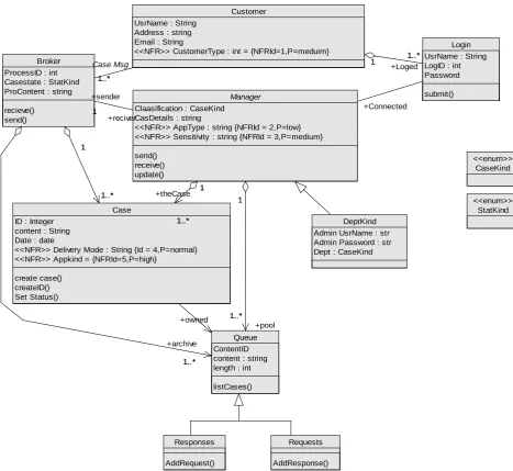
6)An employee should be able to update a case. This is the functionality needed to develop an applica- tion conceptual model (PIM) as we will see in Figure 8. Figure 8 shows a class diagram for the helpdesk sys- tem. The basic structure of the class diagram includes six major classes: customer, login, broker, case, manager, and Queue with their responsibilities and relationships among them. In the case of the manager, one of the responsibili- ties is to provide access to a case in the response queue that has received a message from a broker and send the
updated version back to broker; thus, Case, Queue, and broker have associations to manager. Case has associa- tion to the queue class. Case will be given unique ID and created so each case will represent uniquely an individual customer case which is stored in a queue either as a re- quest if it came from the customer or response if it came from the system. The UI is specified in this PIM but we are not considering this part. It could be possible to cap- ture an entire UI specification from this PIM that could be rendered by an outsourced third-party platform such as a browser.
CaseKind <<enum>>
StatKind <<enum>>
Requests
AddResponse() Responses
AddRequest()
DeptKind Admin UsrName : str Admin Password : str Dept : CaseKind
Login UsrName : String LogID : int Password
submit() Customer
UsrName : String Address : string Email : String
<<NFR>> CustomerType : int = {NFRId=1,P=meduim}
1 1..* 1
+Loged 1..*
Manager
Claasification : CaseKind CasDetails : string
<<NFR>> AppType : string {NFRId = 2,P=low} <<NFR>> Sensitivity : string {NFRId = 3,P=medium}
send() receive() update()
+Connected Broker
ProcessID : int Casestate : StatKind ProContent : string
recieve() send()
1..* 1..*
Case Msg
1
+reciver +sender
1
Queue ContentID content : string length : int
listCases() 1..*
1
+case
1..* 1
1..* +archive Case
ID : Integer content : String Date : date
<<NFR>> Delivery Mode : String {Id = 4,P=normal} <<NFR>> Appkind = {NFRId=5,P=high}
create case() createID() Set Status()
1..* 1 +theCase
1..* 1 1..*
1
+pool 1..*
1
+owned
[image:11.595.61.529.84.513.2]1..*
Figure 8. PIM: Helpdesk system with NFR documented.
functional requirements according to the NFR profile. Tag values are used to denote two pieces of information: ID to identify a NFR and priority (P) which assigns an integer number to indicate a priority level of NFR. These are the elements of the NFR specific-language used to model NFRs as described in 4.2.3 (Task D).
In the PIM shown in Figure 8 there are the following NFRs: Application sensitivity {High, low, medium}, App- Kind{transactional,nontransactional}, CustomerType {nor- mal, durable}, AppType {normal, critical}, and delivery Mode{normal,guaranteed}. (Task D). The interpretation of these NFRs will make sense when we link to design decisions as we will see later.
We now have a helpdesk system conceptual model de- scribing functionality as well as nonfunctional require-
ments.
Figure 9. PSM of messaging system with variability in design decision.
to attend at the time of connection. Connection is Direct type or Indirect type transaction in case of failure.
We can call Queue for the former which allows one receiver per send action and Topic for the later that allows multiple receivers per send. Data can be Persistence type which means using backing store, preserving it in the case of any failure, or it can be NonPersistence. (Task B)
We notice this abstraction deals with concepts that are from implementation space not like the PIM concepts that are from an application domain.
Figure 9 shows the capability to deal with different design decisions configuration that are represented by va- riability (Task A, C). For example Connection is denoted by <<VP>> stereotype which can take Direct or Indirect variants. Likewise session denoted by <<VP>> with its two different variant kinds. The focus on the discussion will be only on variability that is non-functional with res- pect to the PIM.
5.2. Mappings (Task E)
In order to explain how to apply this principle we will describe mappings of this case manually, while it should be automated. The NFR in the PIM of Figure 8 will guide the mapping process to configure a suitable PSM from Figure 9 automatically. For instance, the two data vari- ants: persistence or NonPersistence is selected according to the application need for reliability or performance so delivery mode will determine that. The current case study
says Application Sensitivity is not high and a delivery mode is normal hence these two NFRs are not reliability factors which require maximizing performance. The de- livery would use NonPersistence option which does not necessarily insure message delivery by for example stor- ing message until a receiver becomes available.
Similarly, the Session variation point has two variants: Transacted and Nontransacted. Because the AppType (i.e.
size) NFR is normal application in the help desk PIM Nontransacted variant is the most suitable.
This factor affects performance directly for example when transacted variant is used performance is impacted negatively compared with the Nontransacted mode. This is because there is additional overhead for resource ma- nipulation needed in the system for transaction mode.
Generally in terms of performance indirect connection is contributing positively while direct connection is con- tributing negatively. The same message is forwarded to different subscribers which mean lower resource con-sumption.
Note that we need one of the variants to be set as de- fault because the PIM and PSM are independent so that the default will be selected in case there is no correspon- ding NFR(s). For instance Figure 10 shows that the de-fault variant is selected ([2]) for ConnectionVP if there is no corresponding NFR addressed. We notice also two or more design decisions determined by single NFR such as Appkind can be used to decide both connection and ses- sion variants.
Table 2 shows informally part of mappings from Help- desk system PIM to messaging system PSM with NFRs guidance. It also shows how application concepts turn in- to design concepts. For instance the Case from PIM meta- model which is a unit of work between customers and company holding the necessary information will be map- ped into three objects: Message, Connection and Session. Because we have two kinds of messages and so two different bodies of computations, we need to judge on suitable design by looking into NFRs presented in the PIM according to for example performance or reliability.
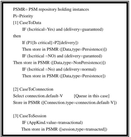
NFRs can be extracted from system specification by different formats and meaning. For simplicity Iscritical (such as OCL style) is used instead of AppType. The mapping rules that can be used to implement the map- pings specified in Table 1 are shown below.
PSMR= PSM repository holding instances Pi=Priority
[1] CaseToData
IF (Iscritical=Yes) and (delivery=guaranteed) then
If (P1[Is critical]>P2[delivery])
Then store in PSMR ([Data,type=Persistence)]) IF (Iscritical =NO) and (delivery=guranteed) Then store in PSMR ([Data,type=NonPersistence)]) IF (Iscritical =No) and (delivery=normal) Then store in PSMR ([Data,type=Persistence])
[2] CaseToConnection
Select connection.default-V [Queue in this case] Store in PSMR ([Connection.type=connection.default-V])
[3] CaseToSession
IF (AppKind.value=transactional)
Then store in PSMR ([session,type=transacted])
Figure 10. Part of informal mappings rules from helpdesk PIM to messaging system PSM.
Figure 10 like pseudo-code shows a sample of map- pings rules to transform PIM instances with existence of priority consideration into PSM instances. For example, [1] describes a conflict situation where if the application Iscritical and at the same time the delivery is guaranteed, the selection of design decision will depends on the hi- ghest priority. In this case persistence (factor of reliabil- ity) is chosen because P1 is greater than P2. Note here priority is used only in the case of NFR values causing a conflict.
We notice by this way an application could be config- ured at the two extremes: reliability and performance using suitable design decisions represented in the design artifact with NFRs guidance. It is also possible to con- figure an application in between these two extremes. Thus our method affords different products with archi- tecture designs at different levels of quality-attributes. Inputs for mappings will be PIM metamodel (holds appli- cation instances), NFRsrepository (NFR instances), PSM metamodel, and Variability (design decision instances).
5.3. Class Methods Mapping
This activity is intended to realize the abstract operations expressed by one kind of behavior diagram for the help- desk PIM metamodel. We can use an activity diagram to show the control flow and instances creation during the execution of the mappings from PIM to PSM at this stage. For example in the behavior instances model of Figure 8, the sendcase method in broker needs to map into the fol- lowing sequence: createObject (connection), createOb- ject (session), createObject (producer) as in the behavior instances model shown in Figure 7. It shows the control flow of mapping activity and relationship occurrences between source (helpdesk behavior model) and target (messaging system model). For example, raise case will be mapped to initialize Connection and sendcase will be mapped to sending process. We can determine PIM (source) and PSM (target) actions from this activity dia- gram. For example PSM activity are, initalizeConnetion, SendingProcess, ReceivingProcess, CreateUniqueRecord, lookupcase, UpdateRecord and createResponse (from 1.1 to 1.7). But still as we mentioned previously more inves- tigation is needed in this place to map a PIM process model to PSM process model and understand this map- ping completely.
6. MDA in the Context of Design Pattern
and SPL
[image:13.595.60.286.457.694.2]Varibility and Nonfunctional requirement concepts are borrowed as we have seen in section. MDA is a special case of design pattern techniques as we will argue in Se- ction 6.1, while MDA and SPL have a synergistic rela- tionship according to observations described in Section 6.2.
6.1. MDA and Design Pattern
The design pattern concept goes back to Christopher Al- exander [24]. His definition identified a relationship be- tween three parts constituting a pattern: problem, solu- tion and context. In software engineering, a design pat- tern is a general reusable solution to a commonly occur- ring problem in software design [25].
6.1.1. Limited to Domains with a Well-Established Code Base
The nature of solution provided by MDA is more specific to the problem domain than the design pattern which is more general because there are many kinds of design pat- terns [26]. A general purpose pattern perspective in solv- ing problems is more expensive in terms of the estab- lishment of working environment than in MDA, which is characterized by its well-established specific backend. Typically, MDA is used to target platform(s) that have al- ready been crafted. For instance, large scale software RDBMS (a complex proven solution) can be utilized automatically by tools which transform PSM relational model after mapping to the SQL language. In contrast, for a pattern to be executed generally involves establishing new tools. For instance, Yacoub, Xue and Ammar [27] proposed their own visual systematic tool.
6.1.2. Separating Concerns Allows Application Logic and Platform to be Variable and Encourages Re-Use
It is observed that design pattern tends to integrate the behavior aspects with implementation aspects which re- sult in risks of platform changing or volatility. Further, some implementation details become suppressed as con- sequence of behavioral variation as in the publish-sub- scribe pattern which does not say anything about remote objects design [15]. If this pattern is used in a distributed environment it becomes necessary to distinguish local from remote objects which is not available as a design decision at design time.
6.1.3. End of Pattern Life Cycle
Design Pattern follows a life-cycle as patterns become more mature and quality increases [28]. MDA produces high quality patterns because PSMs are end of the pattern life cycle. Although the nonfunctional requirement emer- ged first in the design pattern approach, MDA gives a wide opportunity to represent NFR explicitly. It is the
critical requirement that discriminates between pattern architecture designs. In fact, it is still a research question how to graft design pattern with recognition of NFRs. In Buschmann [15] we can observe the role of NFRs in ba- lancing design forces.
6.2. MDA and Software Product Line (SPL)
Software product line engineering is a paradigm to deve- lop software applications (software-intensive systems and software products) using common platforms and mass customization [2]. The intended goal is to avoid reinven- ting the same solution for different applications in order to achieve shorter development time and high quality products (i.e. Nokia mobile applications). There are two distinct development processes adopted by SPL: domain engineering and application engineering. The former is concerned with design for reuse by seeking communal- ties and variability in the software product line. As a re- sult a reference architecture called product line architect- ture (PLA) is established. The aim of the latter is to drive applications by exploiting the variability of the software product line.
6.2.1. Defining Variation Points and Variants
The central concept in SPL is the explicit representation of variability. Variability is a variable item of the real world or a variable property of such an item [16].A vari- ant identifies a single option of a variation point and can be associated with other artifacts corresponding to a par- ticular option (dependency relationship). For example, payment method as a variation point can be realized by variants: payment by credit card or payment by cash, etc. It is necessary in SPL to identify variability by defining variation points and variants, which is used by a selection process to produce different products.
There are two types of variability: Variability in time, which is different versions of the artifact at different times (i.e. performance), while variability in space refers to an artifact in different shapes at same time. For exam- ple “system access by” variation point in a home security system can have two variants: web browser and mobile phone. Variability in space is the central challenge faced by SPL, so management of variability is the main issue in this engineering approach [16].
A set of closely related objects, packaged together with a set of defined interfaces, forms a component [28]. Usu- ally a component-based approach is used to realize SPL concepts.
6.3. MDA in the Context of the Software Product
Line
Both software product line engineering (SPL) and model driven architecture (MDA) are emerging as effective paradigms for developing a family of applications in a cost effective way [3]. SPL through its feature-based mo- dels provides a capability to capture variability in inten- sive systems, while the effectiveness of MDA is primar- ily due to potential for automation it offers for variability in technology. Generally MDA can fit into SPL as an ef- fective software development method. For instance MDA can tackle implementation variability within a specific platform. So the synergistic relationship between the two approaches has been studied recently [4,20,29]. The basic differences between the two approaches are as follows:
6.3.1. MDA Decouples Implementation Model from Application Model
The PSM is constructed as an API to specify the imple- mentation aspects for an intended target such as rela- tional database model. Similarly a PIM model is built which specifies the business logic. This will add value by enabling MDA to tackle technology variability which allows the same PIM to be rendered into different plat- forms or PSMs.
Although components raise the reuse level a little bit, they still suffer from the software evolution problem. For example, any small interface changes will entail finding everywhere the interface is used, changing it to reflect the new interface, testing new code, reintegrating and retest- ing the system as whole. Therefore, a small change in the interface can cause enormous changes by following each code part that refers to this component interface. In con- trast, the PSM, an intermediate subsystem, abstracts this tedious task by concentrating the changes in one place. Also, MDA avoids the problem of features explosion that tends to complicate maintenance [9]. In addition, keeping a mapping function separate avoids swamping the source model (application) with implementation details and re- duces the problem of model divergence because the tar- get (implementation) is generated [29].
Furthermore, MDA increases architecture longevity (ageing) compared to the fact that sometimes PLE suffers from architecture lifespan which may reach end of life [22]. In this case evolving architecture will be expensive or risky. MDA’s potentiality comes where evolving the architecture becomes much cheaper because each of PSMs and PIMs are adapted separately and they do not carry any volatility risks (technology variability).
6.3.2. MDA is Intended to Automate the Craft of Code
The potential of MDA is due to the capability of automa-
tion it offers. It is recognized that if we will be able to formalize the model to the extent that it has no ambiguity and the model is machine readable (executable) then the code in principle can be mechanically generated. MOF is a powerful metamodeling language that realizes this trend by allowing tools to interoperate and accurately modeling the conceptual model of a design language such as UML. Crafting code becomes a model driven process wherein a transformation from source model (PIM) to a target mo- del (PSM) can be automated by for example QVT tools. Eventually the PSM can automatically mapped into text (code). MDA works best if the scale of PSM objects is the same as that of PIM. The mapping function is kept separate so that it can generalize some concepts and it can be repeated many times (repeated design decisions) sho- wing a big picture of reuse. The mapping function can be automated at the instance level because it is an algo- rithmic process in which generic transformation rules are established at the type level. The general feature of auto- mation is the synchronization between the two ends.
6.3.3. Higher Abstraction and Systematic Development Methodology
The main goal of MDA is to raise the abstraction level higher than traditional middleware and 3 GL/4 GLs pro- gramming languages. This means taking advantage of software-platform independence that enables a specifica- tion to execute on a variety of software platform with a stable software architecture design. The granularity of code re-use will increase to the level of a PSM (ADT) in- stead of components as in SPL. The PSM is scoped to this level of code reuse. For example relational database PSM is an abstraction for the family of relational databases above any specific technology. Also, there is a difference between MDA and SPL in defining interfaces to compo- nents and frameworks via an API. In MDA, the interface is not concrete but it is meta-interface exported by mark- ing models [29]. The mappings are externalized and gen- eralized, which can be reused in similar problems.
7. How Design Pattern and SPL Contribute
to E2E2D Engineering
The survey of the relationship among MDA, SPL, and Design Patterns has shown a synergistic relationship. MDA improves each approach by supporting these quail- ties: automation, proper management of technology changes or volatility, high granularity of reuse and more important a capability of integration.
Design Pattern is not an end to end concept because it is an abstraction for software implementation.
Design pattern could be used to construct the architect- ture in E2EDE. It adds value by acting as a proven solu- tion and a documented experience.
SPL is an end to end concept but in addition to the pro- blem of coupling application and implementation toge- ther, it does not tackle the variability in the implementa- tion part. In contrast, E2EDE is mainly addressing this cha- llenge. In addition, there is no concrete link as in E2EDE between higher level models and lower detailed models. SPL engineering gives another insight for E2EDE: the concept of explicit variability representation and mana- gement. Introducing variability explicitly in the PSM helps mainly in its construction. This means a PIM can become informed about variation points that are docu- mented explicitly therefore it becomes possible to auto- mate the design decision process. A UML profile for spe- cifying PLA [3] can fill the gap between PSM and the PLA core assets artifact.
Metamodeling and MDA are an alternative technique successfully used to organize SPL and feature model concepts as demonstrated by Muthig and Atkinson [11]. Furthermore, unlike orthogonal models, the variability model and original model would not be separated, which increases readability.
8. Strategic Messaging System PSM
The philosophy of MDA is to do more investment on me- tamodels so as to hopefully obtain payoff at production
time by producing larger number of products. It can be conceived as the same scale as where database systems and X11 [20] are considered viable.
We have looked at PSM in Figure 9 in the previous section as a specific implementation for helpdesk system. In fact this PSM was built from a general messaging sys- tem perspective. The concepts in this PSM form an on- tology. There are many messaging systems which com- mit to that ontology.
Examples are: Chat system, Email system, instant me- ssaging system, media streaming system, mobile applica- tions, etc.
As we argued before re-use is a major trend in the soft- ware development community. Important are not only re- usable components but also strategic reusable assets like models and transforms.
Table 2 shows a simple configuration for four prod- ucts as a picture of the benefits of re-using the messaging system PSM. Further, it is obvious that the rationale of this specific architecture design does not exhaust the E2EDE approach. An architect can reason about different architecture designs.
[image:16.595.53.539.574.721.2]In Table 3 we see there are number of NFRs common to this set of applications, which are re-used to make a design decisions. They are App-size (i.e. Application size), Iscritical and Delivery. Both App-size and Iscritical are a kind of Package level NFRs while Delivery is a class level NFR because it is about an object class inside the system. Design decisions are: message (data), connection and session, and Acknowledgement mechanisms. In the example of email system two reliability factors are high- er than the other; App-size has lower value than for de- livery and apply-size, therefore message (data) delivery is persistence with Queue type connection and transacted session. The Acknowledgement will be given normal va- lue which is AutoAck. All these values makes reliability higher than performance because of the overhead proce- ssing (i.e. store) which what is said by NFRs. The inverse
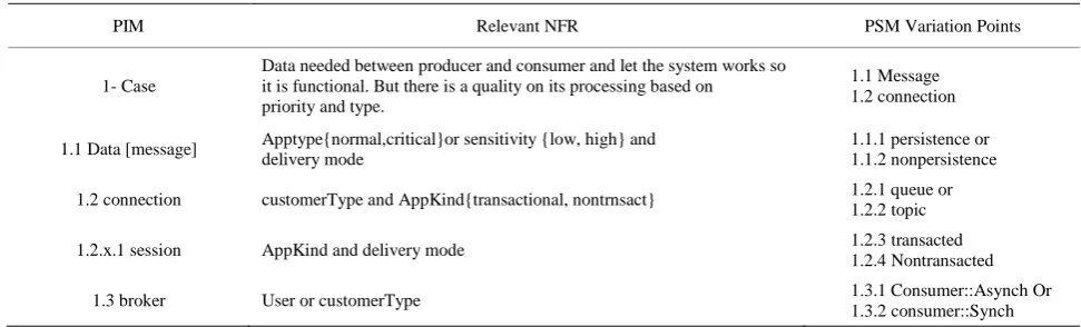
Table 3. Part of mappings from helpdesk system to messaging system.
PIM Relevant NFR PSM Variation Points
1- Case
Data needed between producer and consumer and let the system works so it is functional. But there is a quality on its processing based on priority and type.
1.1 Message 1.2 connection
1.1 Data [message] Apptype{normal,critical}or sensitivity {low, high} and delivery mode
1.1.1 persistence or 1.1.2 nonpersistence
1.2 connection customerType and AppKind{transactional, nontrnsact} 1.2.1 queue or 1.2.2 topic
1.2.x.1 session AppKind and delivery mode 1.2.3 transacted
1.2.4 Nontransacted
1.3 broker User or customerType 1.3.1 Consumer::Asynch Or
1.3.2 consumer::Synch
of this situation typically is in Chat and Forum applica-tion where P1 of applicaapplica-tion size put into highest priority than data delivery and Iscritical so the configuretion of parameters is set to increase performance. The mobile application comes in the middle between performance and reliability more oriented to reliability. Note that this is an arbitrary configuration but any other scenarios are possible. The point is by that we can see an example of NFRs and variability reusing among products in mes-saging systems.
9. How MDA Works
MDA is new trend in software development. This section sketches key points about MDA implementation.
The history of software engineering shows that a soft- ware design model is a complex object that needs to be maintained during a project life cycle and refined over a long period. CASE tool (computer-aided software engi- neering) is used to allow easy model creation, editing, rendering etc. In this case, a tool designer utilizes infor- mation system technology to keep this complex object in a database called a repository. A repository consists of a schema which stores model instances [6]. In fact this re- pository does not need the complete commercial database machinery. There are recently emerging MOF-standards like XMI [30] used as a mechanism not only for persis- tence purpose but also as a mechanism for exchanging models between tools which it was difficult before in a classic CASE tool (i.e. magic draw, rational rose). Many recent MOF-based toolsets support in addition to effi- cient access methods, both system and user- defined API serialization mechanisms in which developers can render a model using an XMI concrete syntax for different pur- poses. There are many tools with different features and capabilities working in this context, extensively studied in [31]. EMF [32] an open platform adopting MDA prin- ciples provides a Java code-generation facility to achieve interoperability between applications based on a MOF meta-modeling framework.
10. E2EDE Implementation
The implementation of E2EDE need to be considered as there is some limitation in current MDA tools. Our ap- proach in this space is to separate working on the model view from the implementation view the same way UML gives a different views for different purposes such class diagram and activity diagram.
The proposed profiles are useful in terms of readability and explicit showing of the NFRs and VPs but for im- plementation it needs suitable representation to fit the MDA computation environment.
There are three reasons underlying the solution sug- gested in this section: source, target and mapping meta-
models. Firstly, current tools have a limitation of recog- nizing a profile instances in a model annotated by a pro- file elements such as MediniQVT [33]. (Tag values are not visible to QVT pattern expressions.) Therefore we suggest a representation for profiles to resolve this issue. Secondly, if we look practically to the mapping the me- talevels concept breaks down when we compare two sys- tems. For instances, if we used UML as PIM metamodel and MOF as PSM metamodel, the mapping is from in-stances of M0 objects to inin-stances of M1 objects. The same is true more generally when we use Profile instan- ces that are at level higher than instances level of the me- tamodel. In our specific case, profile instances are at M1 level while the metamodel instances needed by QVT en- gine are at M0 level. However, OWL-Full [34] can be suggested as an alternative technology to UML which could resolve this solution. OWL has an OWL metaclass
class which is itself a class, so we can build a profile mechanism by declaring subclasses of OWL class.
Finally there is a need for linking a single VP with a set of NFRs and mapping variability should be conside- red. (Task G)
Figure 11 describes the relationship between VP, NFR and a Design Decision. A design decision is one of two kinds: selection which denotes the normal variability exi- sts on PSM, and compiled which represents the mapping variability highlighted in the previous sections. This sort of design decision groups related rules that have some common property which is modeled by the attribute rank. An instance of compiled design decision is associated with an instance of NFR because NFR(s) is the reason behind this grouping.
For example, consider how the mapping variability discussed in Section 4.2.2 could be represented. Also, more information details about design decisions can be added, for instance to compiled subclasses, like the ef- fects and cost of effect etc. However, an instance of a de- sign decision is an opaque rule specifying the creation of valid PSM instances when its precondition is satisfied as shown in the following. A program manipulating this metamodel should differentiate between three modes: de- fault, application of a rule, and conflict resolution. A conflict mode needs to refer to NFR’s priority. Seduo- code based in QVT relation language is shown in Figure 12 .This part showing application of Task F.
Figure 11. PIM to PSM mapping metamodel.
Figure 12. Opaque rules for mapping variability rules.
and Indirect variants respectively: {important, transactio- nal}, {normal, Nontransactional}. Note that variants in PSM are disjoint and covering because they are alterna-tive design elements. NFR and VP are imported from corresponding packages.
The metamodel in Figure 13 is a lightweight UML2.0 metamodel used as an example by the QVT specification. We use this as a base for presentation purposes (Profile). The full work makes use of UML.
The extension or adaptation to this existing metamodel was special NFR (SNFR) metaclass, general NFR (GNFR) metaclass and NFR metaclass. Working with this case study shows that there are two kinds of NFR: package
level (general) and class level (special).
An extension to the same UML simple metamodel could be done for variability model using an extension to the metaclass class to represent variation point, variant and QuailityAttribute. The same extension is found in the literature such as [2,3,12] but there are two problems with this. Firstly, it does not model mapping variability and for example the conflict cases that arise when we link NFRs with variants. Secondly, it is impossible to use the UML toolset to do that modification because it is at the level of UML metamodel. Here the proposed app- roach generally involves Profiles, packages and model manipulation.
The meaning of variability in PSM is somehow diffe- rent from traditional variability in SPL. In E2EDE, vari- ants are disjoint and covering which represents only al- ternative design decisions. These decisions can be over- lapped and not covering in SPL. Variants in E2EDE exist on a PSM artifact to represent Nonfunctional while SPL traditionally represents only functional variability. There is no dependency such as between VP-VP because it is already inherited from the UML design language.
10.1. Packages (Task G)
Figure 13. Simple UML2.0 metamodel extention from QVT specification as Profile implementation.
The relationship program has end to end functionality. It is intended to link a PSM variant with the relevant NFR(s). The traditional mechanism in literature used to model variability is through a subclass structure of the UML class model like [12]. This is suitable for humans but if the system is scaled up, it would be difficult for a human to comprehend that system. The second problem is that some times in these large system names of classes, properties, and association etc, can be ambiguous. There- fore we need a representation mechanism that allows the program to find model elements. MOF and UML support a Package mechanism which has a capability to make names of members unique within the package that owns them. Further it is has a facility to disambiguate names where necessary by adding the package name as prefix. So both human and programs could easily access model elements without ambiguity. Further a package may need to import or merge another package.
Therefore, the semantic operations of incorporating a subclass (variant) in the model will be through legal stan- dard package operations.
In UML2 infrastructure a package [35] is defined to group elements, and provides a namespace for the grouped elements. A package merge is used as basic re-use me- chanism that allows extension by new features. For ins- tance, UML2.1.2 superstructure builds on the Infrastruc- ture library by re-use of the kernel package. It is defined in UML2.1.2 infrastructure as a direct relationship be- tween two packages that indicates the contents of the two packages are to be combined. Conceptually this means there is a resulting element combining the characteristics of both source and target.
Since we modeled VP and V using the generalization concept, a subclass is always an extension for superclass
i.e. by adding new structural features. A package merge has these capabilities. Therefore, a PSM super-subclass structure will be modeled using packages.
![Figure 1. Simplified UML2 metamodel from QVT [8].](https://thumb-us.123doks.com/thumbv2/123dok_us/9040470.400359/4.595.60.285.439.693/figure-simplified-uml-metamodel-from-qvt.webp)