1
A Note on Geographic Systems and Maps of Montserrat, West Indies
Henry M. Odbert1,2 & Stephen Grebby3
1. Montserrat Volcano Observatory, Montserrat
2. Seismic Research Centre, The University of The West Indies, Trinidad 3. British Geological Survey, Keyworth, Nottingham, UK
Abstract 1
2
It is often critically important that geospatial data are measured and mapped accurately, 3
particularly for quantitative analyses and numerical modelling applications. Defining a 4
geographic coordinate system requires a non-unique combination of geodetic techniques (e.g. 5
ellipsoids, projections and geoids). The choice of geographic system presents scope for 6
ambiguity and confusion about geographic data, especially those archived without appropriate 7
metadata. Experience has shown that these confusions have been a repeating source of either 8
frustration or inadvertent error for those using geographic data from Montserrat. This is, in part, 9
probably due to common usage of multiple datums and the existence of numerous topographic 10
data sets recorded during the past 150 years. Here, we attempt to provide a brief introduction to 11
geodetic principles and their application to Montserrat geographic data. The differences between 12
common datums are illustrated and we describe variations in magnetic declination as they apply 13
to field use of magnetic instruments. We include a record of the source of the large-scale 14
mapping data sets that have been used and analysed ubiquitously in the literature. The 15
descriptions here are intended as an introductory reference resource for those using geographic 16
data from Montserrat. 17
18 19
Number of Words: 3352 20
21
Number of References: 18 22
23
Number of Tables: 2 24
25
Number of Figures: 3 26
27
Abbreviated Title: Montserrat Geographic Systems & Maps 28
2
Accurate mapping is essential in most areas of geoscience. To understand geospatial data we 30
adopt coordinate systems in which we are able define position and velocity. However, the choice 31
and specification of the coordinate system is not unique and, over the centuries, geodesists have 32
derived a multitude of methods for describing three-dimensional (3D) geographical data. 33
Commonly, this invokes the use of a reference ellipsoid, which models the approximate shape of 34
the Earth’s surface; a projection, which translates that ellipsoid into two dimensions (2D); and 35
sometimes a specific reference surface from which height is measured (e.g. sea level). Confusion 36
between different coordinate systems can be – and has been on occasions – a source of 37
significant error when using and comparing geospatial data. The explanations and data given 38
here include a brief summary of the most commonly used systems on Montserrat. Descriptions 39
and derivations of various ellipsoids, geoids and projections are widely available elsewhere (e.g. 40
Robinson et al., 1995). Specifications are also provided here to assist configuration of field tools 41
such as handheld GPS receivers. A summary of the changes in magnetic declination for 42
Montserrat since 1995 is also included. The information herein is intended purely as a practical 43
introduction for those using geospatial data from Montserrat, not as an exhaustive description of 44
cartographic methods. 45
46
1. Ellipsoids, Projections and Geoids 47
There exists a plethora of simple geometrical ellipsoidal models that approximately describe the 48
shape of the Earth. An ellipsoid’s shape and size is defined by the lengths of its three mutually 49
perpendicular radii. A geodetic ellipsoid is symmetrical around its polar axis such that its shape 50
may thus be defined by just two parameters: the equatorial and polar radii (a and b, respectively). 51
These may be given explicitly or via a flattening factor, f, that relates a to b, where f= (a-b)/a. 52
Flattening is also often cited in inverse form: 1/f. The origin (centre) of any two ellipsoids may 53
be offset in space. An ellipsoid may thus be described by five parameters: the offset of its origin 54
from the Earth’s centre of mass (dX, dY and dZ – see Figure 1); the equatorial radius; and either 55
the polar radius or the flattening factor. In some cases, additional parameters may be required 56
(e.g. coordinate axis rotation), but this will not apply herein. Ideally, an ellipsoid would 57
approximate mean sea level (or, more specifically, the geoid – see below) on a global scale. 58
However, this is not the case due to the unevenness that means even globally-defined ellipsoids 59
3
rise to many different ellipsoid definitions, with models often optimised to fit sea level well over 61
a particular geographical region. 62
Adopting an ellipsoid as a simplified geometrical representation of the Earth allows for 63
geometrical translation of features on the surface of that ellipsoid onto a 2D plane (i.e. a map). 64
However, in performing such translations (projections), geometrical relationships (e.g. distance, 65
azimuth, shape, area, etc.) cannot all be fully preserved on any single map. The method for 66
projecting information from the ellipsoid onto a map thus depends on which properties takes 67
precedence and requires the according compromises. Numerous projections exist, but focus is 68
given here only to those in common use on Montserrat. The Transverse Mercator (TM) method 69
offers a suitable strategy for map projection on Montserrat and is described in brief in the next 70
section. For small areas, such as Montserrat, distortions due to the curvature of the ellipsoid can 71
usually be neglected. It is notable, however, that such assumptions may be inappropriate for 72
precision applications (e.g. ground deformation surveying). 73
A geoid is an equipotential surface that closely aligns with mean sea level around the globe – 74
typically to within a couple of metres of local mean sea level – and can be measured through 75
precise gravitational surveying. Unlike an ellipsoid, the geoid is complex in its shape, with 76
undulations caused by the heterogeneous distribution of mass around the Earth. Recent geoid 77
models have been derived using a combination of data from spaceborne gravity surveys (e.g. 78
GRACE and GOCE). The geoid offset for a specific location – given as the vertical offset 79
between the geoid model and an ellipsoid – may be computed using published model spherical 80
harmonic coefficients or interpolated from gridded geoid data (NGA, 2012). 81
82
2. Datums Used On Montserrat 83
84
For reasons discussed below, the two most commonly used ellipsoids are the Clarke 1880 and 85
World Geodetic System 1984 (WGS84) ellipsoids. Geographic coordinates are usually expressed 86
either in terms of geodetic latitude and longitude (in degrees) or via a TM projection. Heights are 87
measured relative to a vertical reference surface – usually the ellipsoid or, sometimes, a geoid 88
model. It is important to be sure that a common datum (the combination of ellipsoid, projection 89
and vertical reference) is used when considering multiple spatial datasets. Similarly, it is critical 90
that the implications of the projection (i.e. distortion) are considered in analyses where spatial 91
4
Pre-eruption maps of Montserrat are derived from aerial photographs acquired in the 1950s on 93
behalf of the British Government’s Directorate of Overseas Surveys (DOS, 1983). The map data 94
derived from these surveys were plotted using the Clarke 1880 ellipsoid and either geodetic 95
coordinates or a customised metric TM projection, referred to herein as the British West Indies 96
(BWI) grid. This datum is used by the Government of Montserrat Lands and Survey Department 97
and was initially adopted by staff and colleagues at the Montserrat Volcano Observatory (MVO; 98
e.g. Kokelaar, 2002). In recent years, the use of the WGS84 and Universal Transverse Mercator 99
(UTM) datum has become more prevalent for representing data gathered on Montserrat as it 100
provides a standardised approach to referencing geographic data. The following summaries 101
describe these systems and appropriate parameters are given in Tables 1 and 2. 102
103
2.1 Earth-Centred Earth-Fixed Coordinates
104 105
Positions given in Earth-Centred Earth-Fixed (ECEF) coordinates refer to a 3D Cartesian 106
coordinate system, with its origin at the Earth’s centre of mass (the WGS84 origin, as shown in 107
Figure 1) and axes aligned as follows: the Z axis is approximately aligned with Earth’s axis of 108
rotation (the International Earth Rotation Service, IERS, Reference Pole). The X axis is 109
perpendicular to Z and passes through the IERS Reference Meridian (near the Greenwich 110
Meridian), and the Y axis is mutually perpendicular to Z and X (NIMA, 2004). 111
Values of position, distance, angle and velocity can be defined explicitly and unambiguously in 112
this system without the need of a reference surface or projection. This can be advantageous when 113
handling position or velocity data outside of a geographic context, as there is no distortion due to 114
projection. However, ECEF coordinates bear no intuitive relation to other features on the Earth 115
and are often not useful for cartographic or geographic applications. 116
117
2.2 Ellipsoids
118 119
Two ellipsoids have been used predominantly in mapping Montserrat over the past century: the 120
WGS84 ellipsoid and the more region-specific Clarke 1880 ellipsoid. Geodetic coordinates 121
(degrees of latitude and longitude) can be used in conjunction with any ellipsoid but a given 122
5
In recent decades, the WGS84 ellipsoid has become an international standard for geodetic 124
applications, against which other systems’ parameters are conventionally referenced. The origin 125
of the coordinate system (Figure 1) is taken as the Earth’s centre of mass, measured and updated 126
using satellite and orbital measurements, and is coincident with the ECEF origin. The WGS84 127
ellipsoid was devised as an approximate fit to the global mean sea level (via the geoid), and thus 128
typically results in regional deviations of many tens of metres. The WGS84 ellipsoid reference 129
surface is around 41 m above sea level near Montserrat (Figure 2), for example. Due to changes 130
in the location of the Earth’s centre of mass and the accuracy with which it can be measured, the 131
WGS84 has undergone several revisions since it was first realised. While the differences 132
between versions are small – usually negligible for navigation purposes, for example – they can 133
be significant for precision surveying applications. 134
The Clarke 1880 ellipsoid differs in both shape (more oblate) and origin (offset by about 540 m) 135
from the WGS84 ellipsoid (Table 1, Figure 1). The Clarke 1880 ellipsoid surface is about 136
equivalent to sea level in the Lesser Antilles region and the British Ordnance Survey adopted it 137
for 20th Century mapping work. Significant horizontal and vertical offsets can exist between 138
coordinates referenced to the Clarke 1880 ellipsoid versus the WGS84 ellipsoid. For example, a 139
point in Montserrat defined by geodetic coordinates (lat./ long.) on the Clarke 1880 ellipsoid 140
would be about 400 m northeast of the point with the same coordinates on the WGS84 ellipsoid. 141
The offset is due to the difference in ellipsoid shape and origin and the exact difference depends 142
on the three-dimensional position of the point in question. Furthermore, the vertical difference 143
between the two ellipsoids also varies spatially. In Montserrat, the offset is around 38 m 144
(WGS84 is higher); variations are illustrated in Figure 2. These examples highlight the 145
importance of explicit datum referencing to avoid position ambiguity or errors. 146
147
2.3 Projections
148 149
The common map projection employed for Montserrat is the TM projection. The TM method 150
figuratively uses a cylinder, wrapped around the ellipsoid, with its central axis parallel to the 151
ellipsoid’s equatorial plane. The great circle at which the ellipsoid meets the cylinder is the 152
‘central meridian’ on the ellipsoid. The projection is then performed by ‘unwrapping’ the 153
cylinder from the ellipsoid, translating features on the ellipsoid onto a 2D plane (see illustrations 154
6
chosen central meridian and it is therefore ideal to select a central meridian close to the region of 156
interest. Northing and Easting coordinates may then be measured, in units of length, eastward 157
from the central meridian and northward from the equatorial plane, respectively. Often, an 158
arbitrary offset is applied to the Easting coordinate so that positions west of the central meridian 159
do not have negative values. TM projections can thus be readily tailored to specific cartographic 160
requirements, as desired, and can be applied to any ellipsoid. The BWI grid is an example of a 161
TM projection used for mapping parts of the West Indies region (e.g. DOS, 1983), typically in 162
conjunction with the Clarke 1880 ellipsoid (Table 2). 163
The UTM system is a series of standardised TM projections that cover the globe in a series of 164
sixty numbered ‘zones’; each zone has its own central meridian, spaced six degrees of longitude 165
from the next zone. Any position in the world can be identified by values of Easting, Northing 166
and UTM Zone number, and whether the point is in the northern or southern hemisphere. 167
Subdivision of latitudinal zones in the UTM system (denoted by letters) is somewhat redundant 168
as long as the hemisphere is specified. The UTM system uses the WGS84 ellipsoid (Table 2). 169
Montserrat falls within UTM Zone 20Q (also 20-North or 20N – the latter raising ambiguity with 170
latitude Zone N). 171
It is notable that the choice of TM projection does not inherently define the vertical reference 172
surface (ellipsoid or geoid) against which elevation is measured. However, two common pairings 173
have generally been used on Montserrat: the Clarke 1880 ellipsoid with BWI TM grid or the 174
WGS84 ellipsoid with UTM grid. 175
176
2.4 Geoids & ‘Sea Level’
177 178
The Earth Gravitational Model 1996 (EGM96; NGA, 2012) is used as the reference geoid for the 179
WGS84. Earlier and more recent geoid models exist, with varying sophistication and accuracy. 180
The WGS84 geoid provides a separate alternative as a standard vertical reference surface with 181
the attraction that it is, by definition, close to the average ocean surface level. Figure 2 shows the 182
vertical offset of the WGS84 EGM96 geoid from the WGS84 ellipsoid around Montserrat. The 183
geoid has not generally been used as a vertical reference for Montserrat geographic data owing 184
partly to the additional complexity of computing or interpolating geoid offsets (e.g. Figure 2). 185
7
referenced to the geoid (EGM96) are often used for larger-scale mapping and/or spaceborne 187
surveying such as the Shuttle Radar Topography Mission (SRTM) global topography model. 188
A third convention for measuring topographic height is mean sea level. Sea level can be 189
measured using one or more tide gauges in the area of interested. Commonly, however, heights 190
given ‘above sea level’ (asl) refer directly to the geoid height (NIMA, 2000). This introduces 191
ambiguity in the use of the term ‘sea level’. There are currently no reference tide gauge sea level 192
measurements on Montserrat. 193
194
2.5 Maps of Montserrat
195 196
The most widely available published map of Montserrat (DOS, 1983) is referenced to the Clarke 197
1880 ellipsoid and has coordinates expressed in the BWI TM grid (Easting and Northing, in 198
metres, height in feet) and in geodetic coordinates (latitude and longitude, in degrees and 199
minutes). DEMs derived from this map (described later), along with various archived 200
georeferenced data from Montserrat, use the same system. Since about 2009, MVO have adopted 201
the WGS84 ellipsoid as a reference and use the UTM grid (Zone 20Q, Easting and Northing in 202
metres, ellipsoidal height also in metres). Datum parameters (given in Table 2) may be used to 203
correctly configure instruments, such as handheld GPS receivers, and software appropriately. 204
205
3. Converting Between Coordinate Systems 206
207
It is often desirable or necessary to convert geospatial data from one coordinate system to 208
another. For example, quantitative analyses might be performed using ECEF coordinates and 209
then converted to geographic coordinates for visualisation. Conversion formulae are derived 210
from the geometrical form of each reference system, and are described widely in the literature. 211
There also exist numerous programs and web-based tools for performing coordinate 212
transformations. The software tools named here do not represent an exhaustive list of available 213
options but are given as a starting point. A comprehensive database of reference systems is 214
maintained online by Butler et al. (2012). 215
The ArcGIS software package (ESRI, Redlands, California) and open source equivalents (e.g. 216
QGIS; www.qgis.org) are popular and powerful interfaces for handling and manipulating 217
8
generally capable of relating or converting data between multiple coordinate systems. ArcGIS 219
and many similar programs use the Geospatial Data Abstraction Library (GDAL, 2012) to 220
perform datum translations. GDAL may be freely downloaded and used as a standalone, multi-221
platform program. Programs such as GDAL and proj (Evenden, 2003) perform command-line 222
and batch-mode conversion that allows straightforward incorporation into other programs and 223
scripts. Coordinate systems are often indexed using a unique European Petroleum Survey Group 224
(EPSG) code, as listed by Butler et al. (2012) and in Table 2. The following example command 225
uses the ‘cs2cs’ command in proj to convert a position on Montserrat (near the volcanic vent) 226
from Clarke 1880 BWI TM to WGS84 UTM 20Q coordinates: 227
Input:
228
cs2cs +init=epsg:2004 +to +init=epsg:32620 229
380915 1847084 700 230
Output:
231
587842.27 1847829.34 661.98 232
In this example, EPSG codes (Table 2) are used as shorthand for the two map datums. Datum 233
parameters and other details (such as output precision) can be specified explicitly and input 234
values can be typed (as in this example) or given as an input file. Extensive documentation is 235
available for these and other conversion programs and the reader is directed there for further 236
information. 237
238
4. Digital Maps of Montserrat 239
240
Digital Elevation Models (DEMs) are grids, rasters or point files containing topographic height 241
information. They are an extremely useful resource for many geospatial applications. In the 242
context of Montserrat, DEMs have been essential for measuring topographic changes during the 243
Soufrière Hills Volcano (SHV) eruption as well as for providing constraint on numerical models 244
of eruptive processes. The following descriptions briefly document the origin of large scale 245
Montserrat DEMs that have been widely used by the volcanology community. 246
The British Ordnance Survey’s Directorate of Overseas Surveys (DOS) used photogrammetric 247
survey data – collected in the mid 20th Century – to generate a series of published topographic 248
maps. In 1986 G.Wadge manually digitised the latest edition (DOS, 1983) from original DOS 249
9
retrieval – exacerbated by dense vegetation on the island – and digitisation error. The latter was 251
estimated at about 1/3 of the 50-foot contour interval (G. Wadge, pers. commun.). The resulting 252
‘1995’, or ‘pre-eruption’, DEM (at 10 m grid intervals, available at www.nerc-essc.ac.uk/~gw) 253
has since been used extensively by the research community. The original DEM was generated 254
using the Clarke 1880 ellipsoid and BWI TM grid. 255
The accumulation of erupted volcanic material since 1995 has resulted in major changes in the 256
island’s topography and coastline. Various surveying work has been conducted throughout the 257
eruption to measure and record these changes at different spatial and temporal scales (e.g. Jones, 258
2006; Wadge et al., 2008). An airborne LiDAR survey was commissioned by MVO in 2010 and 259
yielded the most extensive and detailed topographic survey recorded since the start of the 260
eruption. The survey was conducted using a helicopter-mounted scanner with on-board high-rate 261
GPS tracking which was later processed using ground control GPS data supplied by MVO. The 262
survey covered most of the island to the south of the Centre Hills, except for regions above about 263
750 m (asl), which could not be surveyed due to low cloud cover. The 2010 DEM has 1-metre 264
grid intervals and we estimate an RMS point error of 0.17 m from independent GPS 265
measurements. The original DEM data used WGS84 UTM 20Q coordinates with heights 266
referenced to the WGS84 (EGM96) geoid, later converted to ellipsoid height values. 267
Space-borne topographic surveying provides an attractive alternative to airborne and ground-268
based surveying methods, providing wide, contemporaneous. Generating of DEMs using satellite 269
radar interferometry can be impeded by degradation of active volcanic terrain – a problem that 270
will be reduced in data from recent, high-repeat rate satellite missions (e.g. Ferrucci & Tait, 271
2011). DEM data from such endeavours are typically adjusted to fit existing topographic data 272
(e.g. SRTM) and thus adopt the cartographic conventions of the original DEM. Georeferenced 273
satellite topography and imagery data (e.g. radar intensity images, Wadge et al., 2011) 274
commonly use the WGS84 UTM systems, with either geoid or ellipsoid vertical reference. 275
Bathymetric data around Montserrat have been compiled and updated in a similar fashion: 276
original data were derived from 1:50000 scale British Admiralty sea charts based on 19th and 20th 277
Century surveys. Numerous additional surveys conducted since 1998 have been used to map 278
bathymetric changes around Montserrat, particularly the evolution of submarine deposits 279
offshore from the Tar River Valley (due east from SHV). Le Friant et al. (2004; 2010) 280
10
usually inaccessible to large survey ships – was given by Wadge et al. (2010). The map in 282
Figure 2 shows a current DEM, combining data from recent surveys. 283
284
5. Magnetic Declination 285
286
Magnetic declination (the difference in angle between magnetic and true north) changes in space 287
and time. It is important to account properly for declination in work that requires the use of a 288
magnetic compass (e.g. surveying, wind vane installation, etc.). In Montserrat, a correction of 289
about 14°W is required, and this has changed at an average (not constant) rate of about 3’W/yr 290
during the course of the eruption. Figure 3 shows the variation of magnetic declination on 291
Montserrat since 1995, estimated using the International Geomagnetic Reference Field (IGRF-292
11; Finlay et al., 2010). Magnetic inclination (dip of the magnetic field from horizontal) is 293
usually not as critical for standard surveying purposes; on Montserrat, magnetic inclination dips 294
at about 40° and changes by about 0.2°/yr (becoming shallower). Alternative magnetic field 295
models and further information are available from NOAA (2012). 296
297
6. Summary 298
299
This note is intended as a brief introduction, to highlight and document geodetic practices as they 300
have been used in geoscience on Montserrat. We have included a rudimentary description of the 301
fundamental geodetic tools used for handling and manipulating geospatial data and highlight the 302
importance of understanding the influence of their use and mis-use. We have also indicated the 303
conventions that have been used most commonly by researchers during the course of the eruption 304
on Montserrat. 305
306 307 308
Acknowledgements 309
We are indebted to many individuals for their efforts in ensuring that geographic data are 310
properly referenced or translated. Particular thanks to Andrew Simpson, Tom Herring, Adam 311
Stinton, Annde Le Friant, Geoff Wadge, Melanie Froude, Colm Jordan, Francesca Cigna, Sue 312
Loughlin, Ricky Herd and Mick Strutt for useful discussions. We are grateful to Anne Patrick 313
11
their kind assistance. Thanks also to the many unsung individuals who diligently recorded the 315
relevant metadata with their geospatial measurements. We thank Geoff Wadge for a useful 316
review that has improved this manuscript. SG publishes with permission of the Executive 317
Director, British Geological Survey (NERC). 318
12 References & Resources
321
Butler, H., Schmidt, C., Springmeyer, D. and Livni, J. 2012. Spatial Reference. Worldwide Web
322
Address: http://spatialreference.org
323 324
DOS (Directorate of Overseas Surveys) 1983. Tourist Map of Montserrat: Emerald Isle of the 325
Caribbean, 6th Edition, Scale 1:25000. The British Government’s Ministry of Overseas
326
Development. 327
328
Evenden, G.I. 2003. Cartographic Projection Procedures for the UNIX Environment—A User’s 329
Manual. USGS Open File Report 90-284.
330
Ferruci, F., and Tait, S. 2011. EVOSS: European Volcano Observatory Space Services. 5th GEO
331
European Projects workshop, London 8-9 February 2011. Worldwide Web Address:
332
www.evoss.eu/images/stories/pdf/Poster_evoss_londres-1.pdf 333
Finlay C.C., Maus S., Beggan, C.D., Bondar, T.N., Chambodut, A., Chernova, T.A., Chulliat, A., 334
Golovkov, V.P., Hamilton, B., Hamoudi, M. et al. 2010. International Geomagnetic Reference 335
Field: the eleventh generation.Geophysical Journal International, 183 (3) 1216-1230. DOI: 336
10.1111/j.1365-246X.2010.04804.x. 337
GDAL (Geospatial Data Abstraction Library) 2012. Worldwide Web Address: www.gdal.org
338 339
Jones, L. D. (2006), Monitoring landslides in hazardous terrain using terrestrial LiDAR: An 340
example from Montserrat. Quarterly Journal of Engineering Geology & Hydrogeology. 39, 371– 341
373. 342
Kokelaar, B. P. 2002. Setting, chronology and consequences of the eruption of Soufriere Hills 343
Volcano, Montserrat (1995-1999). In: The eruption of Soufrière Hills volcano, Montserrat, from
344
1995 to 1999. T. H. Druitt and B. P. Kokelaar (Eds), Geological Society, London. 345
346
Le Friant, A., Harford, C.L., Deplus, C., Boudon, G., Sparks, R.S.J., Herd, R.A., and 347
Komorowski, J-C. 2004. Geomorphological evolution of Montserrat (West Indies): importance 348
of flank collapse and erosional processes, Journal of the Geological Society, 161 (1), 147–160. 349
350
Le Friant, A., Deplus, C., Boudon, G., Feuillet, N., Trfimovs, J., Komorowski, J.-C., Sparks, 351
R.S.J., Talling, P., Loughlin, S., Palmer, M. and Ryan, G. 2010. Eruption of Soufrière Hills 352
(1995–2009) from an offshore perspective: Insights from repeated swath bathymetry surveys, 353
Geophysical Research Letters, 37(11), doi:10.1029/2010GL043580. 354
355
NOAA (National Oceanic and Atmospheric Administration) 2012. Worldwide Web Address:
356
http://www.ngdc.noaa.gov/geomag/
357 358
NGA (National Geospatial-intelligence Agency) 2012. Worldwide Web Address:
http://earth-359
info.nga.mil/GandG/wgs84/gravitymod/
13
NIMA. 2000. Department of Defense World Geodetic System 1984, 3rd ed., National Imagery
362
and Mapping Agency. 363
Robinson, A.H., Morrison, J.L, Muehrcke, P.C., Kimerling, A.J. and Guptill, S.C. 1995. Elements of Cartography (6th Ed.). Wiley, 674 p.
364
Torge, W. 1991. Geodesy. Walter de Gruyter, Berlin. 264 pp. 365
366
Wadge, G., Cole, P., Stinton, A., Komorowski, J-C., Stewart, R., Toombs, A.C. 2011. Rapid 367
topographic change measured by high resolution satellite radar at Soufriere Hills Volcano, 368
Montserrat, 2008-2010. Journal of Volcanology and Geothermal Research, 199,142-152, 369
doi:10.1016/j.volgeores.2010.10.011. 370
Wadge, G., Herd, R, Ryan, G., Calder, E.S. and Komorowski, J-C. 2010. Lava production at 371
Soufriere Hills Volcano, Montserrat: 1995-2009. Geophysical Research Letters, 37, L00E03 372
doi:10.1029/2009GL041466. 373
Wadge, G., Macfarlane, D.G., Odbert, H.M., James, M.R., Hole, J.K., Ryan, G.A., Bass, V.A., 374
De Angeles, S., Pinkerton, H., Robertson, D.A. & Loughlin, S.C. 2008. Lava dome growth and 375
mass wasting measured by a time series of ground-based radar and seismicity observations, 376
Journal of Geophysical Research, 113 (B8), DOI:10.1029/2007JB005466. 377
14
Table 1. Parameters for two ellipsoids commonly used on Montserrat (from Butler et al., 2012). 382
Name Offset (to WGS84)
dX (m) dY (m) dZ (m)
Equatorial radius, a (m)
Inverse flattening ratio, 1/f
WGS 1984 - - - 6378137.000 298.257223563
Clarke 1880 174 359 365 6378249.145 293.465000000
383 384
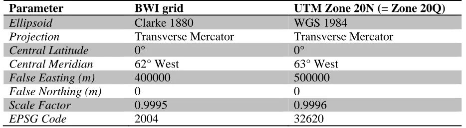
Table 2. Parameters that define the two TM projections most commonly used for Montserrat 385
geographic data (from Butler et al., 2012). 386
Parameter BWI grid UTM Zone 20N (= Zone 20Q)
Ellipsoid Clarke 1880 WGS 1984
Projection Transverse Mercator Transverse Mercator
Central Latitude 0° 0°
Central Meridian 62° West 63° West
False Easting (m) 400000 500000
False Northing (m) 0 0
Scale Factor 0.9995 0.9996
EPSG Code 2004 32620
[image:14.612.63.530.231.360.2]15 Figure Captions
391 392
Figure 1. Cartoon illustration of typical geodetic ellipsoids. The WGS84 ellipsoid (black) has its 393
origin at the Earth’s centre of mass (black dot). The rotational pole, Z, and the prime meridian, X, 394
are defined by the IERS reference pole and meridian (IRM), respectively, as described in the 395
text. The equatorial and polar radii define the flatness of the ellipsoid. Ellipsoids are 396
conventionally defined by parameters relative to the WGS84 frame. Here, the Clarke 1880 397
ellipsoid (red) has an origin that is offset in each of the X, Y and Z dimensions (red dot), as 398
defined in Table 1. The radius and flattening of the ellipsoids also differ. The flattening and 399
offset in this figure is exaggerated for illustrative purposes. The WGS84 X, Y and Z axes also 400
form the orthogonal Earth-Centred Earth-Fixed coordinate axes. 401
402
Figure 2. Map of Montserrat and surrounding bathymetry (grey contours with 100 m intervals; 403
see text for description of DEM). Vertical offsets from the WGS84 ellipsoid are shown for the 404
Clarke 1880 ellipsoid surface (blue contours, 50 cm intervals) and the WGS84 (EGM96) geoid 405
(red contours, 5 cm intervals). The complexity in the geoid model derives from local and 406
regional heterogeneities of mass distribution in the Earth. All height contours are measured in 407
metres from the WGS84 ellipsoid surface (negative values are below the ellipsoid). The coastline 408
of Montserrat is thus shown by a contour at -40 m, rather than at 0, because of the ellipsoid-geoid 409
vertical offset. Horizontal coordinates are given as metres in Easting and Northing using the 410
WGS84 UTM Zone 20Q datum (see Table 2). 411
412
Figure 3 Magnetic declination at 16°42’N 62°11’W (southwest flank of SHV) between 1995 and 413
2015, according to the IGRF-11 model. These corrections may be used to calibrate field 414
compasses or adjust uncorrected azimuth data. 415
dY
dX dZ