Abstract—An inverter-fed three phase squirrel cage induction motor drive system with improved mechanical characteristics is presented. A detailed analytical review of the ideal constant flux control method and the basic
f
v
controlstrategy were undertaken before an improved
f
v
controlmethod, which utilises a low frequency boost-voltage, was developed. This method, unlike the basic
f
v
control method,provides a boost-voltage at low frequencies thereby compensating for the stator impedance drop, offering constant flux operation with maximum motoring torque from zero to rated speed.
Index Terms—Induction Motor, Constant Volts/Hertz
f
v
,Constant Flux, Motor Torque and Speed)
I. INTRODUCTION
Induction machine is the most used in industry because of its high robustness, reliability, low cost, high efficiency and good self-starting capability [1,2,3,4]. The induction motor, particularly with a squirrel cage rotor, is the most widely used source of mechanical power fed from an AC power system. Its low sensitivity to disturbances during operation make the squirrel cage motor the first choice when selecting a motor for a particular application [5]. In spite of this popularity, the induction motor has two inherent limitations: (1) the standard motor is not a true constant-speed machine, its full-load slip varies from less than 1% (in high-horse power motors) to more than 5% (in fractional-horsepower motors) and (2) It is not, inherently, capable of providing variable speed operations[6,7].
These limitations can be solved through the use of adjustable speed controllers [8,9]. The basic control action involved in adjustable speed control of induction motors is to apply a variable frequency variable magnitude AC voltage to
Manuscript received January 14, 2010. This work was supported by the Grant the Principal Author received from the African Network of Scientific and Technological Institutions (ANSTI) Grant Number No. ANSTI.269.10
C. U. Ogbuka (Member IAENG) is a Lecturer in The Department of Electrical Engineering University of Nigeria, Nsukka, Enugu State, Nigeria. He is also a Ph.D Research Student under Prof. M.U. Agu, the co-author. His research interests are in Electric Machine Drives and Power Electronics. Phone: +2348032616466. E-mail: [email protected].
M. U. Agu, is a Professor of Power Electronics and Head of Department of Electrical Engineering, University of Nigeria, Nsukka, Nigeria. E-mail: Phone: +2348076361747 E-mail: [email protected]
the motor to achieve the aims of variable speed operation [10]. The most common AC drives today are based on sinusoidal pulse-width modulation SPWM. However, voltage source inverters with constant volts/hertz
f
v
aremore popular, especially for applications without position control requirements, or where the need for high accuracy of speed control is not crucial [11]. However, since the introduction of field-oriented control theory, almost all research has been concentrated in this area and little has been published about constant
f
v
operation. Its application atlow frequencies is still challenging due to the influence of the stator resistance and the necessary rotor slip to produce torque [12]. In addition, the nonlinear behaviour of pulse-width modulated voltage inverter in the low voltage range makes it difficult to use constant
f
v
drives atfrequencies below 3Hz [13].
II. CONSTANTFLUXCONTROL:PRINCIPLESAND MOTORPERFORMANCE
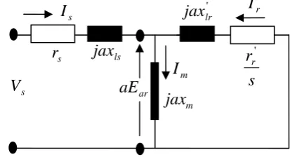
The ideal of the variable frequency, variable voltage control methods is the constant flux control where the magnetizing current is kept constant [10, 14]. As the frequency varies, all the reactances vary accordingly. Taking the operating frequency as
s and
b or
sr as the base (rated) frequency at which the reactancesx
ls,' lr
[image:1.595.329.536.594.706.2]x
, andx
m are determined, then the familiar equivalent circuit for the steady state analysis of squirrel cage induction motor modifies as shown in figure 1 below.Figure 1: Steady State Equivalent Circuit of a Squirrel Cage Induction Motor for Constant Flux Control (a ≤ 1)
A Modified Approach to Induction Motor Stator
Voltage and Frequency Control
Cosmas .U. Ogbuka, Member, IAENG and Marcel. U. Agu, MIEEE
s
V
s
r
r 'm
jax
araE
' lr
jax
ls
jax
sr
sI
' r
I
The per unit frequency ‘‘a’’ is defined as, sr s b s rated s
f
f
a
(1)Where
E
ar, is the rated induced voltage or back emf. For constantI
m,ar m ar m
aE
E
x
E
ax
E
' ' (2) Next, the motor operation for this constant flux control is examined. Under this operating condition, the rotor referred current is 2 ' 2 ' 2 ' 2 ' ')
(
)
(
)
(
)
(
lr r ar lr r ar rx
as
r
E
ax
s
r
aE
I
(3)The resulting motor torque is
2 ' 2 ' 2 ' ' 2 '
)
(
)
(
2
3
)
(
2
3
lr r ar r sr r r sr emx
as
r
E
as
r
P
s
r
I
a
P
T
(4)The maximum and minimum torques,
T
max/min , are determined by setting
0
ds
dT
emto find
s
max/min ; wheremin max/
s
are values of slip at whichT
max/min occur. Therefore, ' ' min max/ lr rax
r
s
(5) Substitutings
max/minfor s in equations 4,' 2 min max/
4
3
lr ar srx
E
P
T
(6) The effect of the term ‘‘as’’ is obvious in equations 3 and 4. It is seen that if ‘‘as’’ is maintained constant, thenI
r' andem
T
are maintained constant analogous to armature voltage control of dc motor up to rated speed. From equation 6, it can be seen thatT
max/min is independent of ‘‘as’’ and thatT
max [image:2.595.49.291.52.166.2]is equal to
T
min in magnitude.TABLE ONE: SAMPLE MACHINE DATA
Rated Voltage 400V
Winding Connection Star
Rated Frequency 50Hz
Number of Poles 6
Rated Speed 960rpm
Stator Resistance 0.4Ω
Rotor Referred Resistance 0.2Ω
Stator Reactance 1.5Ω
Rotor Referred Reactance 1.5Ω Magnetizing Reactance 30Ω
[image:2.595.314.543.59.250.2]Figure 2 shows the Torque-Per Unit Frequency Curves of the Sample Motor of Table One under Constant Flux Control, at a ≤ 1.
Figure 2: Torque-Per Unit Frequency Curves for Constant Flux Control (a ≤ 1)
This control strategy applies up to the rated stator voltage sr
s
V
V
at the rated frequency. Above the rated frequency, a>1,V
s must be kept constant atV
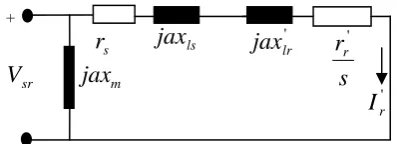
sr to avoid damage to insulation. [image:2.595.316.515.444.516.2]Forcontrol above base speed, where a >1,
I
m is no longer constant but decreasing with increase in frequency. This implies increased magnetizing reactance and continuous decrease in magnetizing current. The approximate equivalent circuit is, therefore, used for analysis in this region of operation. The magnetizing reactance is transferred to the input terminal as shown in figure 3.Figure 3: Approximate Equivalent Circuit for Control above Rated Speed (a ≥ 1)
Under this operating condition, the rotor referred current and the motor torque are, respectively, as shown below.
2 2 2 ' '
)
(
r Ls sr r
x
a
s
r
r
V
I
(7)2 2 2 ' 2 '
)
(
2
3
L r s sr r sr emx
a
s
r
r
V
as
r
P
T
(8)From analysis,
)
(
4
3
2 2 2 2 min max/ L s s sr srr
r
a
x
V
a
P
T
[image:2.595.305.547.577.727.2]
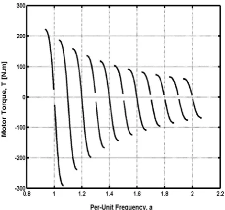
(9)Figure 4 shows the Torque-Per Unit Frequency Curves of the Sample Motor of Table One for control above rated speed (a ≥1). + m
jax
srV
sr
jax
lsjax
lr's
r
r' [image:2.595.46.271.591.728.2]Figure 4: Torque-Per Unit Frequency Curves for Control above Rated Speed (a ≥ 1)
The problem with direct implementation of constant flux drive is that flux (especially magnetizing flux or current) cannot be directly measured due to the lumped nature of winding parameters. Drive engineers have tried to solve this problem by using the constant
f
v
control strategy which permits the indirect control of flux.
III. BASIC
f
v
CONTROL:PRINCIPLESANDMOTOR PERFORMANCE
The approximate equivalent circuit is adopted for the basic
f
v
[image:3.595.305.550.97.648.2]control analysis as shown in figure 5.
Figure 5: Approximate Equivalent Circuit for Basic
f
v
Control (a ≤ 1)
In the equivalent circuit, the operating frequency to rated frequency ratio
a
f
f
rated
s
multiplies the rated terminal voltageV
sr and all inductive reactances. Where,f
rated, is the rated frequency. It is deduced from figure 5, that:2 ' 2
2 ' '
) (
)
( ls lr
r s
sr r
x x a s r r
aV I
(10)
From this, the operating torque
T
em is derived as:2 ' 2 2 '
2 2 '
)
(
)
(
2
3
lr ls r
s
sr r
sr em
x
x
a
s
r
r
V
a
s
r
a
P
T
(11)To obtain the slip
s
max/min at which maximum/minimum torques occur, the first slip derivative of the operating torque,em
T
, is equated to zero.0
ds
dT
em (12) It is obtained, therefore, that2 ' 2
' min
/
)
(
)
(
ls lrs r ax
m
x
x
a
r
a
r
s
(13)Finally, the maximum and minimum torque for operation at a ≤ 1 is obtained as:
)
)
(
)
(
(
4
3
2 ' 2
2 min
max/
lr ls s
s
sr sr
x
x
a
r
a
r
V
P
T
(14) [image:3.595.309.547.364.641.2]The ‘‘+’’ sign is for maximum torque while the ‘‘– ’’ sign is for minimum torque.
Figure 6 shows the Torque-Per Unit Frequency Curves of the Sample Motor of Table One under Basic
f
v
Control at a ≤1.
Figure 6: Torque-Per Unit Frequency Curves for Basic
f
v
Control (a ≤ 1)
With this approach, for
0
a
1
, the magnetizing currentI
m is far from being constant at low speeds because of large drops in the stator impedance when compared tosr
aV
. Hence the need for modifications to compensate for this stator impedance drops at low frequencies [10].+
m
jax
sraV
s
r
jax
lsjax
lr's
r
r'IV. MODIFIED
f
v
CONTROLSTRATEGYAND EXAMPLEMOTORPERFORMANCES
To make full use of the motor torque capability at the start and at low speed, the
f
v
ratio is increased to sustain magnetizing flux at its rated value thereby compensating for the stator resistance drop at low frequencies associated with the basic
f
v
control. The stator voltage is adjusted according to equation 15.
Ka
V
[image:4.595.307.557.51.261.2]V
s
0
(15) This stator voltage is composed of two components. One is a constant term which is an off-set voltage and the other is a frequency dependent component. Where even at zero frequency,V
o compensates for the drop in stator series impedance to make the magnetizing current equal to its rated value. Where, a, is the per-unit frequency andV
o is the stator voltage chosen to give rated magnetizing current at zero speed. Now, to determineV
o andK
, the voltage relationships in the exact equivalent circuit of figure 7 is analyzed.Figure 7: Steady State Equivalent Circuit of a Squirrel Cage Induction Motor for Variable Voltage and Frequency Control From figure 7,
)
)(
(
'ls s
r m ar
s
aE
I
I
r
jax
V
(16)Where
(
)
' ' '
lr r
ar m
ar r
m
jax
s
r
aE
x
jE
I
I
(17)Therefore,
(
)(
)
' '
lr r
ar m
ar ls s ar s
x
as
r
E
x
jE
jax
r
aE
V
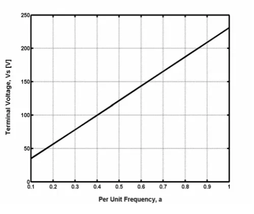
(18)Equation 18 is plotted as ‘‘a’’ varies in the range 0.1≤a≤1. The result is shown in figure 8 below.
Figure 8: Look-Up Plot for Modified
f
v
Control
The constant, K, in equation 15 is the slope of figure 8 while
0
V
is obtained by extrapolating the straight line and determining the point of intersection at a=0.The slope, K, is obtained as 217.614 and
V
0 obtained as 13.3261V (through extrapolation at a =0) Then, equation 15 modifies toa
V
s
13
.
3261
217
.
614
(19) It is seen that even at zero frequency (a=0), the low frequency boost-voltageV
s = 13.3261V compensates for the stator impedance drop. [image:4.595.52.255.411.520.2]Under this condition, the control characteristics are examined as
a
varies from 0.1 to 2 using the approximate equivalent circuit of figure 9.Figure 9: Approximate Equivalent Circuit for Modified
f
v
Control Strategy
From figure 9,
I
r' andT
emare obtained as follows:2 2 2 ' '
)
(
Lr s
s r
x
a
s
r
r
V
I
(20)2 2 2 '
2 '
)
(
2
3
L r
s s r
sr em
x
a
s
r
r
V
as
r
P
T
(21)s
V
s
r
r'm
jax
araE
' lr
jax
lsjax
s
r
s
I
'r
I
m
I
_
a
V
s
13
.
3261
217
.
614
s
r
jax
lsjax
lr's
r
r' ' [image:4.595.46.280.566.687.2]Where,
x
L
x
ls
x
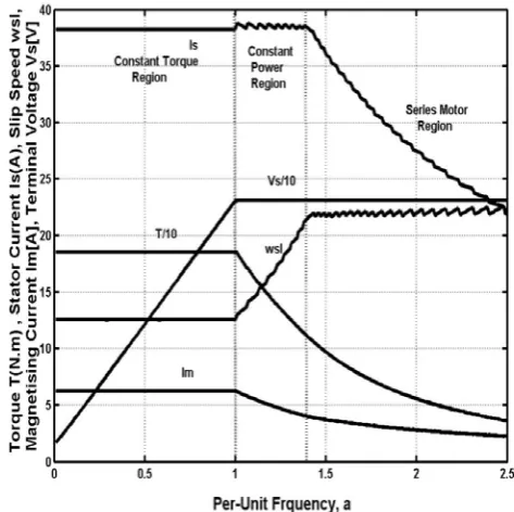
lr'Figure 10 shows the Torque-Per Unit Frequency Curves of the sample motor of Table One under the Modified
f
v
[image:5.595.53.290.133.352.2]Control.
Figure 10: CompleteTorque-Per Unit Frequency Curves for Modified
f
v
Control
V. PERFORMANCECOMPARISMBETWEENTHE BASICANDTHEMODIFIED
f
v
CONTROL STRATEGIES
Due to the stator impedance drop at low frequencies associated with the basic
f
v
control, the magnetising flux and current gradually increases to rated values as frequency tends to rated. This leads to a corresponding gradual increase in the motor developed torque up to rated value at rated frequency. The complete drive strategy, as programmed in MATLAB, is shown in figure 11.
For the modified
f
v
control strategy where the low frequency boost voltage is injected to sustain the magnetizing flux thereby compensating for the stator resistance drop, at the maximum permissible current the drive operate essentially at a constant flux, providing constant torque operation from zero to rated speed [10]. The complete drive strategy, as programmed in MATLAB, is shown in figure 12.
Figure 11: The Complete Drive Strategy for Basic
f
v
Control
Figure 12: The Complete Drive Strategy for Modified
f
v
Control
For both the basic and the modified
f
v
[image:5.595.315.552.332.568.2]characteristic. For speed below rated, the voltage and frequency are reduced with speed to maintain the desired
f
v
ratio or constant flux, and to keep the operation on the portion of the speed-torque curves with a negative slope.
VI. CONCLUSION The modified
f
v
control strategy, the central theme ofwhich is the injection of low frequency boost-voltage, offers the opportunity to realize maximum torque from zero to rated speed, thereby compensating for the low frequency stator impedance drops associated with the basic
f
v
control. Thecontrol strategy generally allows the constant
f
v
controlto operate up to the rated speed beyond which the motor terminal voltage is kept constant at its rated value to avoid damage to motor insulation. A comparison of the complete drives strategies of the basic and the modified
f
v
controlmethods, which describe the operation of the machine in a wide frequency range, were undertaken and the results, as shown in figure 11 and figure 12, confirms the modified
f
v
control as a very good approximation to the idealisticconstant flux control.
ACKNOWLEDGMENT
The authors wish to acknowledge the travel grant, No.ANSTI.269.10, offered to the first author by the African Network of Scientific and Technological Institutions (ANSTI) to deliver this paper during the WCE 2010 in London, United Kingdom..
REFERENCES
[1]Leonhard, W. ‘‘Controlled AC Drives, A Successful Transfer from Ideas to Industrial Practice’’, CETTI 95, Brazil, 1995, pp. 1-12. [2]OKORO, O.I. ‘‘Dynamic Modelling and Simulation of
Squirrel-Cage Asynchronous Machine with Non-Linear Effects’’, Journal of ASTM International, Vol. 2, No. 6, . 2005, Pp. 1-16.
[3]Daniel, L. and T. K. Philip. Control of Induction Machine Drives. CRC press LLC, Illinois, 2002.
[4]MacDonald, M.L. and P. C. Sen. ‘‘Control Loop Study of Induction Motor Drive Using D-Q Model’’, IEEE Transaction on Industrial Electronics and Control Instrumentation, Vol. 26, No. 4, 1979, Pp. 237-241.
[5]Ostovic,V. Computer-Aided Analysis of Electric Machines. Prentice Hall International (UK) Ltd, 1994.
[6]Okoro, O.I, ‘‘MATLAB Simulation of Induction Machine with Saturable Leakage and Magnetizing Inductances’’, Botswana Journal of Technology, No. 2, Vol.13, 2004, Pp. 20-28. [7]Fitzgerald, A.E. Electric Machinery. 5th Edition, McGraw-Hill
Inc, New York, 1990.
[8]Marino, R., S. Peresada and P. Valigi, ‘‘Adaptive Input-Output Linearizing Control of Induction Motor’’, IEEE Transaction on Automatic Control, Vol. 38, No. 2, 1993, pp. 208-221.
[9]Zhou, K. and D. Wang,. ‘‘Relationship Carrier-based Vector Modulation and Three Phase Carrier-based PWM: A Comparative Analysis’’, IEEE Trans. Industrial Electronics. Vol.49, No. 1, 2002, pp. 186-195.
[10] Bose, B.K. Power Electronics and Variable Frequency Drives. IEEE Press, 1997.
[11] Hussein, S. and R. Issa, ‘‘Improving Mechanical Characteristics of Inverter- Induction Motor Drive System’’, American Journal of Applied Sciences Vol.3, No.8, Pp. 1961-1966.
[12] Alfredo, M.G., T. Lipo and D.W. Novotny, ‘‘A New Induction
Motor
f
v
Control Method Capable of High-Performance
Regulation at Low Speed’’, IEEE Trans. Ind. Application, Vol. 34, No. 4, 1998, Pp. 813-820.
[13] Sepe, S. and L. Lang, ‘‘Inverter Non-Linearities and Discrete-Time Vector Current Control’’, IEEE Trans. Ind. Application, Vol. 30, No. 1, 1994,Pp. 62-70.