Estimation of Wave Loads and their Effect on Piled
Structures
Mr. Ankit Bellad1, Prof. R. D. Deshpande2 1
PG Student, Gogte Institute of Technology, Belagavi.
2
Prof. Dept. of Civil Engineering, Visvesvaraya Technological University Belagavi
Abstract: A well versed study and knowledge in interpreting the behavior and magnitude of sea waves at a given location is very much essential for proper planning and design of marine structures. This helps to improve the quality and mitigates the difficulty in construction. The designer should keep in mind attaining smooth and efficient use of marine structures in rough sea conditions. This paper makes an attempt to understand the sea environment, wave nature and their impacts on piled structures Keyword: wave force, wave hydrodynamics, wave propagation, marine structures, currents, wave slam.
I. INTRODUCTION
Generally the waves are generated by wind action, due to the disturbance created by the wind imparting on to the face of sea water, the sea water tries to restore its position of equilibrium by the action of gravity and thus results in generation of wave what we call as wind generated gravity waves. Marine structures are subjected to fury of wave and water forces over time, which can broadly be grouped as breaking wave loads, non-breaking wave loads, water current loads and wave slam loads. Various wave theories are studied to make an attempt to accurately derive the equations for various wave loading conditions. These equations derived contain various parameters affecting the particular wave loads such as the drag/inertia/slam coefficients, tidal levels, velocity of wave, roughness/size/shape of structures etc.
Sea environment is highly unpredictable, the preliminary data required for the calculation of wave loads are got from mathematical model studies. Mathematical model Studies are done to understand the tidal hydrodynamics and wave propagation and also the sea conditions like the bathymetry, Tides, Tidal currents, wave data in deep sea are estimated from these studies with greater accuracy. Parameters which may cause considerable impact on wave loads such as marine growth, dredging of sea beds, wave velocity variation during ebbing and flooding phase and superposition of wave with water current are some of the important considerations to be made while calculating the wave load for accurate results.
II. LITERATURE REVIEW
Central water and power resource station(CWPRS), Pune “Installation of the telemeter wave height recorder" reports D and R of scheme 4. MOST[1] and World Meteorological Organization's (WMO) “Guide to Wave Analysis and Forecasting”, Publication No.702 in World Meteorological Organization, Secretariat of WMO, Geneva. M. J [2] provide the studies that have been undertaken at various stations to understand the hydrodynamics of water particles and propagation of wave. The spectral wave model studies indicate the predominant wave directions at certain near shore depth of region and hence they give an indication that any floating object will have highest impact in the predominant wave direction. The wave data in deep sea is recorded and frequency distribution of wave heights from different directions during monsoon, post monsoon, non-monsoon period and for the entire year at various locations are tabulated and presented in the form of the wave rose diagrams. The hydrodynamic studies also indicate the significant changes in tide induced currents in the vicinity of harbour area. Suggestions for proposal of breakwater structures where the shore is not well sheltered by lands are made with demonstrations showing the circulation of currents in the harbour with and without breakwater structure. Wave tranquility studies with model indicate the wave heights at the berth and permissible tranquility limit for non-breaking wave and breaking wave condition. The tidal currents are measured at various locations also the time history of velocities and directions are observed at different locations. The maximum current recorded and the direction of current during flood and during ebb is recorded.
coefficient of drag, coefficient of inertia, time period etc. are explained also the various limitations and approximations to be adopted while calculating the forces on marine structures have been listed in these manuals.
III. MATHEMATICAL MODEL STUDIES
1) Model Study Involving Wave Propagation: Studies are carried out in two stages 1) Transformation of wave parameters viz. wave height, period and wave direction from deep waters to 5m depth using spectral wave model. 2) Wave tranquility studies using Boussinesq Wave model to examine wave tranquility at the marine structure location.
2) Model Study Involving Tidal Hydrodynamics: Initially the tidal hydrodynamic model studies are carried out to simulate the flow condition under the existing condition. The tide and current data available at CWPRS under the existing conditions are used to calibrate these models initially.
3) Mathematical Modeling: In the study of mathematical modeling, two modules of wave model i.e. Model-A and Model-B are used for interpretation of wave field and its penetration near the shore in the harbour respectively. The 2-dimensional hydrodynamic model Model-C is used for simulating the flow field in the model area. Brief descriptions of these models are given below.
4) Model-A: As waves travel from deep sea to shallow coastal waters, they undergo changes in direction and height due to the processes of refraction and shoaling. The computation of wave transformation from deep to shallow coastal waters are carried out using Model-A. This model is designed as a wind and wave spectral model which is based on un-structured meshing. This model explains the generation, collapse and decay and also the transformation of waves generated by the winds, It also explains the swells observed in the offshore areas which are important in the transformation of waves from offshore to inshore. It also includes physical phenomena of wave growth by action of wind, white capping dissipation, bottom frictional dissipation, dissipation caused by induced depth breaking wave.
5) Model-B: Mathematical model Model-B carries out studies related to disturbance observed in waves inside harbour. Model-B is designed with Boussinesq equations that are time dependent by conservation of momentum and mass evaluated by the integration of equations of 3-dimensional flow also considering vertical acceleration. They operate in time domain, so that irregular waves can be simulated. The non-linearity and dispersion of frequency is also included in this equation. The frequency dispersion is included in the flow equations by taking into account the effect of vertical acceleration or the curvature of stream lines on pressure distribution. Model-B replicates the effects of diffraction, shoaling, refraction and partial reflection from resisting land peaks and boundaries and bed frictions.
6) Model-C: It is very much essential to understand the wave dynamics related to current velocity and tidal levels. Shallow water 2 dimensional equations govern the study of flow of water in marine environment near coast. They are derived when 3-dimensional equations of motion by Navier Stokes are vertically integrated. The following assumptions for simplifications: a) Flow is considered incompressible, b) There is a proper mixture of flow without and variation of density. c) There is negligible vertical acceleration. d) Modeling of bed stress is possible. Based on the scheme of Crank Nicholson the ADI (Alternate Direction Implicit) finite difference techniques are used to solve the governing equations. This entails covering the estuary with a mesh or grid and discretising elevations and velocities in space and time to fit on this grid. Replication of the flow condition over a time period is obtained from the solution at every grid point for the equations.
Site conditions recorded for planning and design of marine structures:
a) Bathymetry: The bathymetry of a sea bed keeps changing from one location to other over time, there is an essential requirement of obtaining minimum draft for ships to sail with no obstructions therefore proper existing condition of sea beds is to be recorded and interpreted for planning of near shore marine structures.
b) Tidal Currents: The maximum current recorded during flooding and during ebbing phase are recorded along with the direction of current during these phases. The time history of velocities and directions observed at different locations are used for model studies.
d) Permissible Wave Heights: The permissible wave disturbance at the berthing place depends on the ship size, mooring and berthing system, and the method of loading and unloading used at berth and on orientation of the berth with respect to wave direction etc.
e) Transformation Of Wave Through Deeper Waters To Shallow 5m Depth Near Shore: Wave direction and transfer function (ratio of wave heights) in 5m depth for waves with 10 sec wave period with different directions of wave incidence at the offshore boundary are tabulated.
f) Growth Of Marine Organisms On Sea Structures: Micro and macro marine organisms are present in sea water such as the algae, mollusks, hard shells, barnacles, sea worms, etc. The marine growth is a result of these organisms sticking over the surface of the structures and grow over these structures leads to increase in diameter of the plies, any such growths needs to be considered in the analysis. Like while considering wave subjected on exposed piles. The diameters of piles are increased by 7.5 cm on either side. Total of 15cm are to be added to the actual pile diameter.
g) Navigable Depth And Dredging: The draft of vessel i.e. vertical linear immersion of stable floating vessel added with the vertical clearance available at the bottom of the ship, if this navigable depth required is greater than the water depth available at site then the ships cannot be allowed to enter into the harbour. Therefore the basin characteristics need to be modified. 'Dredging' which is defined as the process of excavating the sea bed below sea water has to be opted in order to maintain the navigation depth. The hydrographic survey with vertical and horizontal control has to be studied and then decided if the dredging is required. Some of the piles located at the periphery tend to fall in boundary zone of dredging which is a sloping ground which attains its original bed level before dredging hence the soil spring levels of these boundary piles are different than that of normal piles. It can also be observed during the analysis in STAAD models with increase in dredged levels there is a huge increase in the moments observed because of the impact of lateral load at high tide levels, this was due to the increase in lever arm with respect to force causing moment.
Fig 1: The Hydrographic charts providing Fig 2: Bathymetry generated using Fig3: 3-D view of the computational
bathymetric information at the project site Model A model with seabed levels
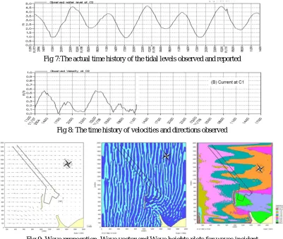
[image:3.612.48.539.351.711.2]Fig 7:The actual time history of the tidal levels observed and reported
[image:4.612.105.506.76.415.2]Fig 8: The time history of velocities and directions observed
Fig.9: Wave propagation, Wave vector and Wave heights plots for waves incident
Fig 10a) Flow pattern in proposed condition in vicinity Fig 10b) Flow pattern in proposed condition in vicinity of proposed development during peak flooding. of proposed development during peak ebbing.
IV. WAVE AND CURRENT LOADS ON PILED STRUCTURES
Marine structures are subjected to fury of wave and current forces over time, which can broadly be grouped as breaking wave loads, non-breaking wave loads, water current loads and wave slam loads. Various wave theories are studied to make an attempt to accurately derive the equations for various wave loading conditions.
A. Non Breaking Wave Load As Per Coastal Engineering Manual
The total wave force (Ft) exerted on a cylindrical pile in-line with the wave direction is obtained by addition of drag force (Fd) and inertia force (Fi) on the cylindrical pile. In case of calculating the drag and inertia force it is essential to know the basic
[image:4.612.149.502.436.556.2]Ft = Fd + Fi =C ρg D HK + ρg H DK
Where,C & C are Inertia and drag coeeficeints,ρ= mass density of fluid, H = Height of wave, D =
Diameter of pile, K & K are dimensionless parameters that depend on the specific wave theory used in the integrations. The total
wave load is dependent on drag coefficient C and inertia coefficient C . C and C are functions of shape and size of object when they are fixed they are dependent on following:
1) Keulegans-Carpenters number (Kc): It is defined as the ratio of maximum drag force to the maximum inertia force. When, Kc is less than 5 Inertia force becomes dominant, Kc is greater than 5 Drag force becomes dominant. The maximum drag to maximum inertia ratio is taken equal to total horizontal motion of the particle divided by the diameter of pile, i.e Kc = Umax*T/D, Where, U(max)= maximum velocity of wave cycles, T= Period of wave , D= Pile Diameter. Refer Fig 11a) for variation of C and C against Kc.
2) Reynolds Number (Re): It is defined as ratio of Inertia force to Viscous force, i.e, Re = ( ) Refer Fig 11b) for
variation of C and C against Re.
3) Roughness Factor: Marine growth in the form of algae, mollusks, hard shells, barnacles, sea worms, sea weeds etc over the time course start effecting the structure which results in the overall increase in the effective diameter of piles with increases in effective mass which leads to change in the observed flow patterns and change is eddy structure which ultimately effects in the change of wave forces. Although the laboratory studies have concluded that there is very less effect of marine growth on value of inertia coefficient C but several studies have concluded that the drag coefficient C may change appreciably leading to a value 2 or 3 times greater than original initial value. Refer Fig 11c) for variation observed in drag and inertia coefficient with change in roughness
Fig 11a) Variation observed in C and C against Kc Fig 11b) Variation observed in C and C against Re
Fig11c) Variation observed in C and C with change in roughness
Variation in the values for and in code provisions: Many on-field and lab studies have been done to account the effects of all such factors like eddy shedding , history of past flow , turbulence in initial stages, irregularity of wave and its directionality, locality conditions, reduction of data techniques. By accounting all these factors following are some of the recommended values of and
in various codes:
a) Indian marine code IS4651 Part 3, Clause 5.7.5.1 recommends the value of C = 0.53 and C = 2.
b) DNV recommends value of C in a range 0.7 to 1.2 and C value as 2.
c) American Petroleum Institute (A.P.I.) recommends value of C in a range 0.6 to 1.0and C value in the range from 1.5 to 2.
B. Water Current Loads
Water currents in the sea are generated by strong winds which are the results of temperature changes in atmosphere. Water current loads can be calculated as per CL. 5.6 of IS 4651 part 3 .When the water current direction is parallel to the piles considered, the equation for calculating the intensity of pressure exerted on piles in given by P= 52 KV2(as per IS code)where P is the Pressure intensity due to water current in kg/m2,V is the velocity of the current at the point where the pressure intensity is being calculated, in meter per second, and K is a constant having values depending on different shapes of piles (0.66 for Circular piles). These loads are applied to each piles as member varying load in transverse, longitudinal and skew direction at 20 degree direction. In analysis models the current load needs to be increased by 25% and applied along with non breaking wave load at length 0.85*depth of water. As per British standard codes BS 6349-1-2000, CL 38.2 we have for uniform prismatic structural members immersed in a uniform current, the steady drag force, which acts at the centroid of the area normal to the flow, can be calculated from the expression FD= 0.5(CDρV2An), Where FD is the steady drag force in kN; CD is the dimensionless time-averaged drag force coefficient; r is the water density in t/m3; V is the incident current velocity in m/s; An is the area normal to flow in m2. Following are some discussions on water current load:
1) From the above equations it is clear that current loads are mainly dependent on the square of velocity of water current
2) Currents velocity needs to be accurately recorded at various locations (Refer Fig 8). The maximum current needs to be recorded during both flooding and ebbing phases (Refer Fig 10a & 10b).Also the current directions during the flooding and ebbing phase need to be known for proper alignment of marine structure and planning protection armors for structures
3) The waves which are traveling with certain velocity and direction keep superimposing on current flow therefore when the currents are in the same direction as that of wave, leads to increase in wavelength and velocity of current hence there needs to be enhancement of current loads on structures by a suitable factor. In general practice the current loads are enhanced by 25% considering the effect on superposition of waves.
4) The constant term 'K' is dependent on shape of piles for circular or semi circular faces the value corresponds to 0.66, for square end face K=1.5, for triangular cut face with included angle taken as 30 degrees or lesser angle K= 0.5, for triangular cut face with included angle taken as greater than 30 degrees but not greater than 60 degree will be equal to 0.5-0.7 and for included between 60 to 90 degree K= 0.7-0.9, Structures with equilateral circle arches of cuts and ease waters K= 0.5, structures cut arches and the ease waters when intersect at 90 then K=0.45
5) From equations it is clear that the current loads depend on the velocity and drag coefficient which are again dependent on the roughness and shape of piles as shown in figures below
C. Wave Slam Load
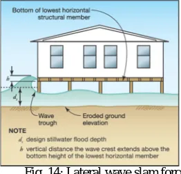
[image:7.612.230.361.136.262.2]Wave slamming is the striking action of rising wave crests onto the elevated cross head of marine structure due to which both lateral and vertical loads are exerted on the supporting structure. The lateral slam force exerted by wave on cross head of piled platform is calculated from the below equation.
Fig. 14: Lateral wave slam force
= *w = 0.5 ℎ
Where, Fws = Total waves slam force in ‘lb’ along lateral direction; fws = Wave slam force in ‘lb/ft’ along lateral direction; Cs = Coefficient of wave slam force it considers the effects of duration of slam force and
total stiffness of the structure under consideration. Typical slam coefficient value recommended for residential structures near shore in 2.0; w = unit weight considered of water in sea or in fresh water bodies; Unit weight of fresh water = 62.4 lb / ft3; Unit weight of salt waters in sea = 64 lb / ft3; ds = Still water level (SWL) in ‘ft’; h = vertical height in ‘ft’ that the crest of wave extends above the soffit of floor beam or joist; w = Total length in ‘ft’ of the floor beam or joist under the impact of wave slam. Following are some of the observation and discussions on wave slam loads:
1) Calculated load from above equation for wave slam force leads to a very high lateral force being exerted onto the structure. This is a reason in marine structure the decks, cross heads or beams of the structure are raised above highest high tide level in order to avoid the wave slam forces hitting at the sides and on the soffit in upward direction. In cases where the platform cannot be raised certain breakwater structures can be placed which break the wave and reduce to height of waves and velocity in vicinity of the harbours.
2) Unlike the inertia and drag coefficient, the wave slam coefficient is used in the Bea et al.-1999 and McConnell et al.-2004 provides information for accurate estimation of slam coefficient.
3) Wave slam induces highest wave moment in piles among all wave loads and current loads. The base moment is high due to increase in lever arm length between slam force exerted at the of top cross head/deck/beam to pile bottom fixity level.
4) Wave slam force is dependent on height of wave crest and still water level at a particular location inside the water body. Proper estimation of tidal levels is got from wave data recorded at site locations.
5) Wave slam force exerted on the soffit of pile caps and cross beams will result in uplift force which induces tension forces in the piles affected.
REFERENCE BOOKS
[1] Central water and power resource (CWPRS),Pune “Installation of the Telemeter wave height recorder" reports D and R of scheme 4. MOST[1] [2] World Meteorological Organization's (WMO) “Guide to Wave Analysis and Forecasting”, Publication No.702 in World Meteorological Organization,
Secretariat of WMO, Geneva. M. J[2]
[3] Shahul Hameed and Baba M, T.S. -1989 book on “Ocean Waves Studies And Applications”, Centre of Earth Sciences Studies, Trivendrum[3] [4] Costal engineering manuals EM 1110-2-1100 (Part VI) Change 3 (28 Sep 11) [4]
[5] The Shore Protection Manual(SPM-1984) Coastal Engineering Research Centre, US Department of Army Corps of Engineers Waterways Experiment Station, Vicksburg, Mississippi[5]
[6] Sarpkaya.T and Issacson.M's -1981 “Mechanics of Wave Induced Forces on Offshore Structures”, Van Nostrand Reinhold [6] [7] The American Petroleum Institute (API) [7]
DESIGN CODES