Design and Performance Analysis of Solar Hybrid
Power Generator
R. Vijay1, G. B. Sathishkumar2, C. Ezhilarasan3
1, 2, 3
Department of Mechanical Engineering College, Arasu Engineering College, Kumbakonam – 612501, Tamil Nadu, India.
Abstract: In our country due to over population the demand for energy is growing day to day. The earth receives solar power continuously with a potential of 178 billion MW which is about 10000 times the world’s demand. The solar energy is a renewable energy source and it is not polluting the environment like fossil fuels. If all buildings of the world are covered with solar PV panel. It can fulfil the electrical requirements of the world. The efficiency of solar panel ranges from 13 to 16 %, which is a posing a difficulty for implementation. The aim of our project is to design and analyse the performance of combined solar photovoltaic (PV) panel and thermo electric generator (TEG) system. The bismuth telluride TEG is placed beside the PV panel which utilizes both light and heat energy for power generation. The efficiency of PV panel will be increased by the addition of regulating mirror and the TEG effectively convert the solar radiation into electrical energy.
Keywords: Solar PV panel, TEG, Bismuth telluride, Renewable energy, Power generation
I. INTRODUCTION
The sun is the most plentiful energy source for the earth. All wind, fossil fuel, hydro and biomass energy have their origins in sunlight. Energy from the sun falls on the surface of the earth at a rate of 120 petawatts, (1 petawatt = 1015 watt). This means all the solar energy received from the sun in one day can satisfies the whole world’s demand for more than 20 years.
Devices that scavenge energy from the ambient surrounding environment have become a popular topic for research. For some applications, energy scavenging eliminates the need for batteries or increase the time between battery replacements. One ambient energy source found in our environment is a temperature change (thermoelectric-See beck) effect. This form of ambient energy is found in the human body, machines, buildings, bridges, furnaces, staircases, and indoor and outdoor temperature differences. The application of TEGs based on thermoelectric effects (or Seebeck, Peltier, Thomson effect) is made possible by direct conversion of temperature differences to electrical power.
The Seebeck effect occurs when a temperature difference exists between two dissimilar electrical conductors or semiconductors, producing a voltage across two materials. Conversely, when a voltage is applied to the thermoelectric generator, it creates a temperature gradient.
A. Solar Radiation
Sun is a sphere of hot gaseous matter with a diameter of 1.39 x 10⁹. metre. Due to its temperature, sun emits energy in the form of electromagnetic waves, which is called radiation energy.
The energy from the sun is transferred to the earth in the form of photons (small packet of energy) moving at the speed of 3 x 10⁸ metre per second. When photons are absorbed by a metal, their energy is converted into heat energy.
When photon falls on plants their energy is combination with O2 is converted to chemical energy of plants (Photosynthesis
process).When photon falls on solar cells, their energy is converted into electrical energy. The heat energy received on the earth through photons is responsible for earth’s temperature. The heat also causes evaporation of water which results in rains.
The uneven heating of the earth’s surface causes wind flow. The amount of solar radiation reaching at different parts of the world is not the same. It varies from location to location and season to season. Therefore, for designing and estimating the potential output from a solar energy system, the knowledge of amount of solar radiation available in a given location is required.
B. Solar Spectrum
1) Distribution Of Solar Spectrum In Terms Of Wavelength And Amount Of Energy Carried
TABLE 1.2.1
C. Types Of Solar Panel
Photovoltaic cells or PV cells (solar cell) can be manufactured from a variety of different materials.Despite this difference, they all perform the same task of harvesting solar energy and converting it to useful electricity. The most common material for solar panel construction is crystalline silicon which has semiconducting properties. Hundreds of these solar cells are required to make up a full photovoltaic array.
There are four main types of solar panels that are commercially available, and they include
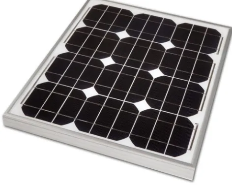
1) Monocrystallinesilicon PV Cell: These cells are composed primarily of silicon crystals. To produce these, a cylindrical crystal of silicon is "grown" from molten silicon. This crystal is then cut into thin slices and shaped into a hexagon so that they fit together well on the solar panel. These cells are smooth in appearance and are rigid, thus they must be mounted in a sturdy frame to prevent them from breaking. Generally speaking, these cells have efficiencies of 13-16% and are the most efficient of the silicon-type cells. Additionally, these panels yield more power per unit area and are thus more space efficient. As well, these panels live longer than polycrystalline varieties and perform better in low light conditions. However, they are more expensive and time consuming to produce than the polycrystalline variety. These cells also do not perform as well in cold conditions.
[image:2.612.206.442.517.705.2]2) Polycrystalline Silicon Pv Cell: These cells are also composed primarily of silicon, but instead high purity molten silicon is shaped using a cast and cooled under controlled conditions in a mould. It sets somewhat irregularly into multi-crystal form, giving the final product a speckled appearance, shown in Figure 2. This square block is then cut into thin slices and the slices are arranged on the panel. The cell is then coated with an anti-reflective coating (which gives the cell its blue colour) to ensure maximum absorption of light. These cells generally have efficiencies of 12-16%, and are less expensive than monocrystalline varieties.
Figure. 1.3.2 Poly crystalline silicon PV cell
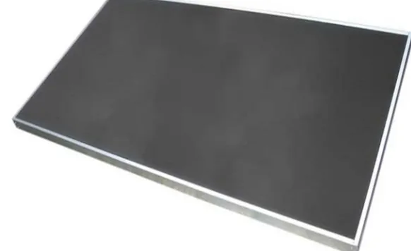
3) Amorphous Silicon PV Cell: This type of cell is made from non-crystalline or amorphous silicon and is one type of thin film cell. The film of amorphous silicon is sprayed as a gas onto some surface, such as glass or flexible rubber material. After this a conducting grid and electrical contacts are attached. This cell is especially thin.So, less raw material is needed as compared to crystalline silicon cells. These are fairly inefficient cells, only about 6-8% efficient, and are thus not suitable for use on residential developments as they require large amounts of space. However they are still used in a number of solar devices. This type of cell is generally found in solar powered calculators or other small solar devices. One property of these cells is that their power output is reduced over time, especially in the first few months of use. However after these few months the output does tend to stabilize.
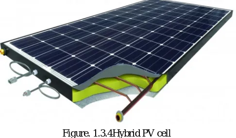
[image:3.612.156.447.530.708.2]4) Hybrid PV Cell: These types of cells are simply PV cells that use two different types of PV technology. For example, a hybrid cell could be composed of a monocrystalline PV cell covered by a layer of amorphous silicon. These cells generally perform well at high temperatures and have efficiencies exceeding 18%.However, these cells can be very expensive.
Figure. 1.3.4Hybrid PV cell
5) Other Type Of Cell: The four types of cells listed above are the most commonly used solar cells, however there are many other types of cells that exist but are not used widely. There are many other kinds of thin film cells that are built using some material other than silicon. These cells include cadmium telluride (9-11% efficient), copper indium gallium selenide (sometimes known as CIGS, they are 10-12% efficient), and organic photovoltaic cells. However, the only cell that is as cost-efficient as silicon panels is currently the cadmium telluride cell. CIGS cells show the most promise in terms of efficiency in the future, and contain smaller amounts of toxic cadmium than other alternatives. Organic photovoltaics are simply photovoltaic cells that utilize inexpensive plastics and electronics that are made of conductive organic molecules. They are not widely used. For more on organic photovoltaics, Concentrating photovoltaics are also an option, but are not widely used.
II. LITERATURE SURVEY
A. The performance of a combined solar photovoltaic (pv) and thermoelectric generator (teg) system, r. Bjørk, k. K. Nielsen The performance of a combined solar photovoltaic (PV) and thermoelectric generator (TEG) system is examinedusing an analytical model for four different types of commercial PVs and a commercial bismuth telluride TEG.The TEG is applied directly on the back of the PV, so that the two devices have the same temperature. For c-Si, CIGS and CdTe PV cellsthe combined system produces a lower power and has a lower efficiency than the PV alone, whereas for an a-Sicell the total system performance may be slightly increased by the TEG.
B. Hybrid photovoltaic-thermoelectric system for concentrated solar energy conversion: experimental realization and modelling ofer beeri,1,a) oded rotem,2 eden hazan,1 eugene a. Katz,3,4avi braun,3,b) and yaniv gelbstein1,2
An experimental demonstration of the combined photovoltaic (PV) and thermoelectric conversion of concentrated sunlight (with concentration factor, X, up to 300) into electricity is presented. The hybrid system is based on a multi-junction PV cell and a thermoelectric generator (TEG). The latter increases the electric power of the system and dissipates some of the excessive heat. For X200, the system’s maximal efficiency 32%.
C. Performance Characteristics Of A Low Concentrated Photovoltaic Thermoelectric Hybrid Power Generation Device Tianjun Liao, Bihong Lin*, Zhimin Yang
A theoretical model of a hybrid power generation device consisting of a low concentrated photovoltaic (CPV) module and a thermoelectric generator (TEG) is established in this paper. The expressions for the efficiency and power output of the hybrid device are derived and the performance characteristics of the device are presented and discussed in detail, based on non-equilibrium thermodynamics theory and law of conservation of energy.
D. Thermal-photovoltaic solar hybrid system for efficient solar energy conversion yu. Vorobieva,*, j. Gonza´lez-herna´ndezb,1, p. Vorobievc, l. Bulatd
the heat energy from the part of solar spectrum not absorbed in the semiconductor material of the cell; the other with concentration of the whole solar radiation on the PV cell working at high temperature and coupled to the high temperature stage. The possibilities of using semiconductor materials with different band gap values are analyzed, as well as of the different thermoelectric materials. The calculations made show that the proposed hybrid system could be practical and efficient.
E. Performance Analysis Of Photovoltaic–Thermoelectric Hybrid System With And Without Glass Cover Ying-Ying Wu, Shuang-Ying Wu⇑, Lan Xiao
This paper establishes a theoretical model for assessing the performance of glazed/unglazed photovoltaic-thermoelectric (PV–TE) hybrid system. To enhance the heat removal, nanofluid is served as heat sink. Firstly, a performance comparison between glazed and unglazed system is given. It is suggested that, under the condition of higher figure of merit Z and concentration ratio C, as well as enhanced transmissivity of glass cover, glazed system may be competitive or even superior to the unglazed one. Environmental effect such as wind velocity, is also a significant factor which may be ignored in the existing researches.
F. Smart Power Generation From Waste Heat By Thermoelectric Generator 1prashantha.K, 2sonam Wango
Electricity in present there is a shortage of fossil fuel, oil, gas, etc. burning of these fuels causes environmental problem like radio activity pollution, global warming etc. So that these (coal, oil, gas) are the limiting resources hence resulting new technology is needed for electricity generation, by using thermoelectric generators to generate power as a most promising technology and environmental free and several advantages in production. Thermoelectric generator can convert directly thermal (heat) energy into electrical energy.
G. Case Study of Solar Power Producing Efficiency from a Photovoltaic System Ching-Lung Lin
To study the efficiency increasing of electric energy generation in the Photovoltaic System is concentrated on this paper. There are four cases to improve the efficiency of power producing from the Photovoltaic System. This article not only describes the differences of facilities before and after the proposal, but also evaluates the electric energy generation efficiency and improved results for each proposal. Finally, the better efficiency of all improving ways is analyzed to get into conclusions in order to provide further improvement and reference for the industry in the future. Overall, these proposed methods can improve the efficiency of solar photovoltaic electric energy generation in about 30.18%.
H. Efficiency Calculation of a Thermoelectric Generator Mohammed Habeeb Shareef1,Abdul Sajid2, Aamer Abdul Majeed3, Mohammed Abdul Baseer Adnan4
An experimental investigation has been carried out to identify the most suitable cooling system techniques to achieve a stable and sustainable power output. This paper depicts the working and efficiency calculation of a thermoelectric generator. The thermoelectric generator works on the Seebeck effect which is the temperature difference between two dissimilar electrical conductors or semiconductors producing a voltage difference between two substances. Thermoelectric cooler uses the heat waste from a number of sites and can generate electricity. The experiment is carried out at low cost with standard equipment and hence efficient in many ways.
III. PROBLEM IDENTIFICATION
A. More space is required for power production. B. Efficiency is less.
C. Cost for power production is high.
D. Power production is affected by wind velocity.
IV. OBJECTIVES
A. To produce the electricity by utilizing both light & heat energy from sun. B. To reduce the area used for power production.
V. WORKING METHODOLOGY
A. Flow Diagram
Figure.5.1. Flow diagram of power production
B. Working Principle
When sunlight fed on reflecting mirrors it will reflected inside the system at the same time direct sunlight also fed on system. These sunlights fed on solarpanel kept inside the system through which the light energy directly converted into electricity. On other hand due to sunlight fed on system significant amount of heat energy will be accumulated inside the system. These heat energy directly converted into electricity with the help of thermo electric generator which works based on seebeck effect. These two electricity stored in battery. The charge level of battery is controlled by charge controller.
The following two principles involve to produce electricity are
1) Photovoltaic Effect: Photons in sunlight hit the solar panel and are absorbed by semiconducting materials, such as silicon. Electrons are knocked loose from their atoms, causing an electric potential difference. Current starts flowing through the material to cancel the potential and this electricity is captured.
Literature survey
Analysis of minimum
Solar radiation
Design of solar box collector
Selection of PV panel
& TEG
Fabrication of HYBRID
POWER GENERATOR
Observation and Tabulation
Figure.5.2.1 Photovoltaic effect
[image:7.612.193.420.387.711.2]2) Seebeck Effect: When the junctions of two different metals are maintained at different temperature, the emf is produced in the circuit. This is known as Seebeck effect.
Figure.5.2.2 seebeck effect
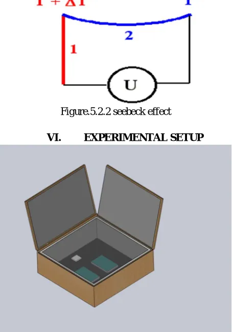
VI. EXPERIMENTAL SETUP
VII. DESIGN AND PERFORMANCE ANALYSIS OF SOLAR BOX COLLECTOR
[image:8.612.204.411.105.244.2]A. Design Of Solar Box Collector
Figure. 7.1 Design of solar box collector
[image:8.612.90.524.282.470.2]B. Ansys Model Of Solar Box Collector
Figure. 7.2Ansys model of Solar box collector
VIII. OBSERVATION AND CALCULATION OF SOLAR BOX COLLECTOR
A. Observation Of Temperature
TABLE :1
DAY: 1 TIME: 01.00 pm DATE: 13.03.2018
S. NO TIME (min) TEMPERATURE (oC )
1 00 32
2 05 38
3 10 44
4 15 50
5 20 58
6 25 65
7 30 71
[image:8.612.100.502.522.722.2](TEMPERATURE VS TIME ) CHART: 1
TABLE: 2
DAY: 2 TIME: 01.00 pm DATE: 19.03.2018
S. NO TIME (min) TEMPERATURE (0C )
1 00 34
2 05 43
3 10 48
4 15 54
5 20 63
6 25 72
7 30 76
8 35 80
(TEMPERATURE VS TIME ) CHART: 2
0
20
40
60
80
0
5
10
15
20
25
30
35
T
E
M
P
E
R
A
T
U
R
E
(
0C
)
TIME (min)
DAY 1
0 10 20 30 40 50 60 70 80 900 5 10 15 20 25 30 35
TABLE: 3
DAY: 3 TIME: 01.00 pm DATE: 06.04.2018
S.NO TIME (min) TEMPERATURE (0C )
1 00 34
2 05 45
3 10 49
4 15 53
5 20 66
6 25 74
7 30 85
8 35 90
(TEMPERATURE VS TIME ) CHART: 3
B. Calculation Of Solar Box Collector Efficiency 1) STEP 1:To find solar radiation intensity ;
The annual solar radiation intensity reports are given below, Rmax = 951.4 W/m2
Rmin = 600 W/m2
2) STEP 2: To find effective surface area of Solar box collector ; Area of inner side of solar box collector (A1) = bxh
= 0.460x0.240 = 0.1104 m2 Area of outer reflective glass ( A2) = bxh
= 0.445x0.415 =0.3693 m2 Area of transparent glass (A3) = bxh
=0.405x0.405 =0.1640 m2 Effective area (Ae) = (4A1 + 2A2 +A3)
=(4x0.1104)+(2x(0.1846)+(0.1640) = 0.9748 m2
0
20
40
60
80
100
0
5
10
15
20
25
30
35
3) STEP 3: To find heat input(Q1 ); Radiation intensity in Watts,(Q1) = Rmin x Ae
= 600 x 0.9748 (Q1) = 584.97 W 4) STEP 4: To find heat losses;
Heat losses = {heat transfer by conduction + heat transfer by radiation} To find heat transfer by conduction;
Qconduction = -k A ( T1 – T2 )
= (- 0.4227x10⁻³) ((4x0.1104)+(0.1640)) (348 – 307) = -0.01049 W
To find heat transfer by radiation
Qradiation= ɛ x σ x A x (T14 – T24)
= (0.8) (5.669 x 10⁻⁸) ((4x0.1104)+(0.1640)) ( 3484– 3074) = 158.83 W
5) STEP 5: To find heat output; heat output (Q2) = Q1 – losses
= 584.97 – ( 0.01049 )+(158.83) (Q2) = 426.13 W
6) STEP6: To find efficiency ;
Efficiency, Ƞsystem = heat output / heat input
= 426.13 / 584.97 = 0.7284
Ƞsystem = 72. 84 %
IX. COMPONENTS AND DESCRIPTIONS
A. Polycrystalline Silicon PV Cell
These cells are also composed primarily of silicon, but instead high purity molten silicon is shaped using a cast and cooled under controlled conditions in a mould. It sets somewhat irregularly into multi-crystal form, giving the final product a speckled appearance, shown in Figure 2. This square block is then cut into thin slices and the slices are arranged on the panel. The cell is then coated with an anti-reflective coating (which gives the cell its blue colour) to ensure maximum absorption of light. These cells generally have efficiencies of 12-16%, and are less expensive than monocrystalline varieties.
B. Bismuth Telluride Teg Modules
[image:12.612.227.387.170.290.2]The power module is designed and manufactured by a unique technology for converting heat energy directly into electricity. The thermoelectric module is based on Bi2Te3 and can work at temperatures as high as 260°C (500F) continuously and intermittently up to 380C(680F) without degrading. The thermoelectric module will generate DC electricity as long as there is a temperature difference across the module. The more electricity will be generated when the temperature difference across the module increases, and the efficiency of converting heat energy into electricity will also increase.
Figure. 9.2Bismuth telluride TEG modules
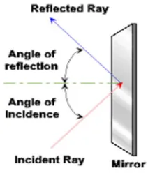
C. Reflecting Mirror
A mirror is an object that reflects light in such a way that, for incident light in some range of wavelengths, the reflected light preserves many or most of the detailed physical characteristics of the original light, called specular reflection. This is different from other light-reflecting objects that do not preserve much of the original wave signal other than color and diffuse reflected light, such as flat-white paint.
[image:12.612.255.361.407.531.2]The most familiar type of mirror is the plane mirror, which has a flat surface. Curved mirrors are also used, to produce magnified or diminished images or focus light or simply distort the reflected image.
Figure. 9.3 Reflecting mirror D. Transparent Glass
The glass that having the property of transmitting rays of light through its substance so that bodies situated beyond or behind can distinctly seen.
[image:12.612.210.401.589.706.2]E. Plywood
[image:13.612.231.385.117.254.2]Wood material that is manufactured from thin layers or “plies” of wood veneer that are glued together with adjacent layer having their wood grain rotated up to 90o to one another.
Figure.9.5 Plywood
F. Thermocol
Thermocol is a polystyeren substance which is a synthetic petroleum product. The molecules are developed as a substance named
[image:13.612.250.362.316.458.2]stretch polystyrene. Thermocol is a good resister of cold and heat but since it is a petroleum product it dissolves in any solvent of petroleum.
Figure. 9.6Thermocol
G. Charge Controller
A charge controller, charge regulator or battery regulator limits the rate at which electric current is added to or drawn from electric batteries. It prevents overcharging and may protect against overvoltage, which can reduce battery performance or lifespan, and may pose a safety risk. It may also prevent completely draining ("deep discharging") a battery, or perform controlled discharges, depending on the battery technology, to protect battery life. The terms "charge controller" or "charge regulator" may refer to either a stand-alone device, or to control circuitry integrated within a battery pack, battery-powered device, or battery charger.
[image:13.612.247.365.609.682.2]H. Thermometer
[image:14.612.146.469.118.228.2]Thermometer is a device which can able to measure the temperature and the temperature gradient.It has mercury in its bulb and scales (Celsius &Fahrenheit)
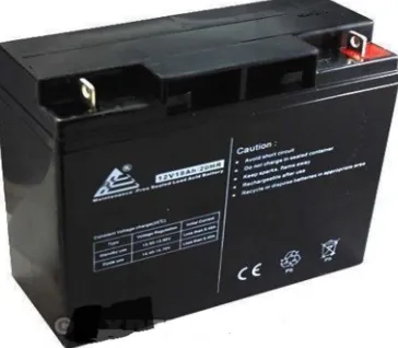
Figure. 9.8 Thermometer I. Battery (lead-acid 12v,6amp)
[image:14.612.216.398.362.521.2]A rechargeable battery, storage battery, secondary cell, or accumulator is a type of electrical battery which can be charged, discharged into a load, and recharged many times, as opposed to a disposable or primary battery, which is supplied fully charged and discarded after use. It is composed of one or more electrochemical cells. The term "accumulator" is used as it accumulates and stores energy through a reversible electrochemical reaction. Rechargeable batteries are produced in many different shapes and sizes, ranging from button cells to megawatt systems connected to stabilize an electrical distribution network. Several different combinations of electrode materials and electrolytes are used, including lead–acid, nickel– cadmium (NiCd), nickel–metalhydride (NiMH), lithium-ion and lithium-ion polymer (Li-ion polymer).
Figure. 9.9 Battery: (lead-acid 12v,6amp)
X. OBSERVATION AND CALCULATION OF TEG AND PV
A. Observation Of Teg
Table: 1
S. NO T1(0C ) T2 (0C ) ȠTEG
1 32 32 0%
2 32 38 1.95%
3 32 44 3.92%
4 32 50 5.88%
5 32 58 8.50%
6 32 65 10.79%
7 32 71 12.75%
(Efficiency Vs Temperature Difference ) Chart: 1
TABLE: 2
S.NO T1 (0C ) T2 (0C ) ȠTEG
1 34 34 0%
2 34 43 2.89%
3 34 48 4.54%
4 34 54 6.49%
5 34 63 9.42%
6 34 72 12.35%
7 34 76 13.65%
8 34 80 14.95%
(Efficiency Vs Temperature Difference ) Chart: 2
0 1.95 3.92 5.88 8.5 10.79 12.75 14.38 0 2 4 6 8 10 12 14 16
0 6 12 18 26 33 39 44
E
F
F
IC
IE
N
C
Y
(
%
)
TEMPERATURE DIFFRENCE (T
2-T
1)
DAY 1
0 2.89 4.54 6.49 9.42 12.36 13.65 14.95 0 2 4 6 8 10 12 14 160 9 14 20 29 38 42 46
E
F
F
IC
IE
N
C
Y
(
%
)
TEMPERATURE DIFFRENCE (T
2-T
1)
Table: 3
S.NO T1 (0C ) T2(0C ) ȠTEG
1 34 34 0%
2 34 45 3.52%
3 34 49 4.87%
4 34 54 6.49%
5 34 67 10.72%
6 34 76 12.35%
7 34 85 16.57%
8 34 90 18.20%
(Efficiency Vs Temperature Difference ) Chart: 3
B. Calculation Of Thermo Electric Generator Efficiency
1) Efficiency by which material is capable of generating power K-1{ Z }
Z = [
]
Z = [
√ . . √ . . ]
Z = 2197.8 K-1 2) Conversion unit { M }
M = 1 + ( + )
M = 1 + . ( 348 + 307)
M = 848.39 3) Ideal efficiency { Ƞideal }
Ƞ ideal=
3.52 4.87 6.49 10.82 12.35 16.57 18.2 0 2 4 6 8 10 12 14 16 18 20
11 15 19 32 40 51 56
E
F
F
IC
IE
N
C
Y
(
%
)
TEMPERATURE DIFFRENCE (T
2-T
1)
Ƞ ideal=
.
.
Ƞ ideal = 0.13320
4) Optimum efficiency { Ƞoptimum}
Ƞ optimum= 0.13320 X 100
Ƞ optimum= 13.32 %
C. Calculation Of Solar Panel Efficiency
1) Panel 1: Efficiency of panel 1 without solar box collector: Vout= 5.2 V
I out= 0.551A
Efficiency Ƞ = power output / (area of solar panel X std solar intensity ) = ( 5.2 X 0.551) / ( 0.0168 X 600 )
= 0.2842 Ƞ = 28.42 %
Efficiency of panel 1 with solar box collector: V max= 5.8 V
I max= 0.586 A
Efficiency Ƞ = power output / (area of solar panel X std solar intensity ) = ( 5.8 X 0.586) / ( 0.0168 X 600 )
= 0.3371 Ƞ = 33.71%
2) Panel 2: Efficiency of panel 2 without solar box collector: Vout=5.4 V
I out= 0.28A
Efficiency Ƞ = power output / (area of solar panel X std solar intensity ) = ( 5.4 X 0.28) / ( 0.011025 X 600 )
= 0.2285 Ƞ = 22.85 %
Efficiency of panel 2 with solar box collector: V max= 5.86 V
I max= 0.3 A
Efficiency Ƞ = power output / (area of solar panel X std solar intensity ) = ( 5.86 X 0.3) / ( 0.011025 X 600 )
= 0.2657 Ƞ = 26.57%
D. Combined Power Efficiency Of Solar Panel Without Solar Box Collector
ȠPV= (28.42 + 22.85) / 2
= 25.64 %
E. Combined Power Efficiency Of Solar Panels With Solar Box Collector
ȠPV= ( 33.71 + 26.57 ) / 2
= 30.14 %
F. Overall Power Efficiency { PV + TEG}
Ƞ overall = (30.14 + 13.32) / 2
XI. COST ESTIMATION
S. NO COMPONENT MATERIAL QUANTITY COST
1 System Plywood,
Thermocol, Reflecting glasses, Transperant glass.
7+ 4+ 6+ 1
1850
2 Solar panel Polycrystalline 2 800
3 TEG Bismuth Telluride 1 409
4 Charge controller - 1 450
5 Battery Lead – acid 1 800
6 Multimeter - 1 140
7 Connecting wires - Required 100
TOTAL 4549
XII. CONCLUSION
Thus the combined performance of solar photovoltaic panel and thermo electric generator ( TEG ) were analysed based on the readings. The area for power production was reduced by the hybrid power generator ( HPG ) with the help of reflective mirrors in the solar box collector. The hybrid power generator ( HPG ) can also be used to harvest thermal energy for heating and cooking purposes. Due to the design of solar box collector and insulation. The efficiency of photovoltaic cell is increased by nearly 30.14% from existing 25.64% and the ȠTEGreaches 13.32% with temperature difference of 41 0C
REFERENCES
[1] The performance of a combined solar photovoltaic (PV) and thermoelectric generator (TEG) system, R. Bjørk, K. K. Nielsen
[2] Hybrid photovoltaic-thermoelectric system for concentrated solar energy conversion: Experimental realization and modelling Ofer Beeri,1,a) Oded Rotem,2 Eden Hazan,1 Eugene A. Katz,3,4Avi Braun,3,b) and Yaniv Gelbstein1,2
[3] Performance characteristics of a low concentrated photovoltaicethermoelectric hybrid power generation device Tianjun Liao, Bihong Lin*, Zhimin Yang [4] Thermal-photovoltaic solar hybrid system for efficient solar energy conversion Yu. Vorobieva,*, J. Gonza´lez-Herna´ndezb,1, P. Vorobievc, L. Bulatd [5] Performance analysis of photovoltaic–thermoelectric hybrid system with and without glass cover Ying-Ying Wu, Shuang-Ying Wu⇑, Lan Xiao [6] Smart power generation from waste heat by thermoelectric generator 1prashantha.k, 2sonam wango
[7] Case Study of Solar Power Producing Efficiency from a Photovoltaic System Ching-Lung Lin
[8] Efficiency Calculation of a Thermoelectric Generator Mohammed Habeeb Shareef1,Abdul Sajid2, Aamer Abdul Majeed3, Mohammed Abdul Baseer Adnan4 [9] Photovoltaic solar panel for a hybrid PV/thermal systemAuthor links open overlaypanel R.Zakharchenkoa
L.LiceaJiménezaS.A.PérezGarcı́aa
P.VorobievbU.Dehesa-CarrascocJ.F.Pérez-RoblesaJ.González-HernándezaYu.Vorobieva [10] Effect Of Dust On The Performance Of Solar PV Panel Dayal Singh Rajput1 K. Sudhakar2
[11] D. Flahaut, T. Mihara and R. Funahashi, N. Nabeshima, K.Lee, H. Ohta and K. Koumoto, JOURNAL PHYSICS 100,0=184911 (2006) [12] Il-Ho Kim1, Soon-Mok Choi, Won-SeonSeo and Dong-Ik Cheong, Kim et al. Nanoscale Research Letters 2012, 7:2
[13] DrissKenfaui, Guillaume Bonnefont , Daniel Chateigner ,Gilbert Fantozzi, Materials Research Bulletin 45 (2010) 1240–1249.
[14] M.M. Farid, A.M. Khudhair, S.A.K. Razack, S. Al-Hallaj, A review on phase change energy storage: materials and applications, Energy Convers. Manage. 45 (9–10) (2004) 1597–1615.
[15] D. Zhou, C.Y. Zhao, Y. Tian, Review on thermal energy storage with phase change materials (PCMs) in building applications, Appl. Energy 92 (2012) 593– 605.