Abstract—A combination of computational models and theoretical methods have been used to study the contact of hip resurfacing devices under normal/central and edge loading conditions. The techniques have been developed and are based on the finite element method. It has been found that the study of hip joint modelling, numerical methodologies of mechanical wear simulations and shakedown analysis can be developed to study the contact mechanics and biotribology of hip resurfacing devices under central and edge loading conditions. Each method developed in this study provides a unique platform to study these problems.
Index Terms—Biotribology, contact, finite element analysis, shakedown, wear.
I. INTRODUCTION
he study of contact mechanics, wear and surface damage of hip replacement and resurfacing devices have been considered since very early implantations and the longevity of the devices are becoming increasingly important. The wear and surface damage of these bearing surfaces occur through normal gait loading conditions, however, another particular problem is the stripe wear patterns observed on both metal-on-metal (MOM) and ceramic-on-ceramic (COC) patient retrievals [1], [2] and hip simulator studies [3], [4]. It has been claimed that edge loading occurs during the walking cycle of the patient; therefore ‘microseperation’ is simulated into each cycle during experimental wear testing [5]. The laxity of the hip joint is known to lead to microseperation during the gait cycle, and fluoroscopy studies have revealed how edge loading of the hip joint is caused by lateral sliding of the femoral component during gait [5], [6].
Contact analysis, wear assessments and the application of shakedown theory all play any important part in improving the performance of designs within contact problems where cyclic loading occurs. For a component under cyclic loading any residual stresses can act to protect the component from plastic deformation by ensuring purely elastic material behaviour is reached in the longer term. It is possible that shakedown theory can be applied to contact surfaces at the micro asperity level between two devices in contact [7], and the theory can also be applied to assess the repetitive rolling and sliding contacts for elastic-perfectly plastic materials
Manuscript received March 02, 2012; revised April 17, 2012. This work was supported and funded in by the EPSRC (Engineering and Physical Sciences Research Council).
M. Ali is with the School of Engineering, University of Warwick, Coventry, CV4 7AL, UK (e-mail: [email protected]).
K. Mao is with the School of Engineering, University of Warwick, Coventry, CV4 7AL, UK (e-mail: [email protected]).
[8]. Results from experimental hip simulator studies have also shown an increase in surface roughness as the number of contact cycles increase, which can further justify the application of shakedown theory at an asperity level. Shakedown theory is based on Koiter’s and Melan’s theorems. Where Koiter’s theorem defines the upper shakedown limit and kinematic shakedown theorem, and Melan’s theorem provides the lower shakedown limit and static shakedown theorem [9].
Previous studies have used a number of inspection techniques to assess the surface wear zones [10], [11], however very few assess the subsurface at these zones. In one study, the subsurface structure of metal-on-metal hip implants have been inspected at the primary wear zones (under normal ISO gait loading conditions) and stripe wear zones (under swing phase load conditions) during experimental simulator testing. The subsurface assessments of both experimental tested components and patient retrievals show similar microstructures following patient usage and testing. There were no significant differences between the subsurface microstructure changes in the primary and stripe wear zones [12].
As a separate but related technique for studying mechanical wear of orthopaedic devices, the Archard wear model [13] has been used with finite element analysis techniques. Although the Archard wear model appears in many forms, the form most appropriate to be used within the finite element method has been described by (1) [14] where
H is the linear wear depth, Kw is the dimensional wear coefficient, p is the contact stress and s is the sliding distance.
ps K
H w (1) The purpose of this study was to develop techniques to assess the contact mechanics for wear modelling wear and application shakedown theory to cyclically loaded hip resurfacing devices, particularly those under normal and microseperation conditions leading to edge loaded hip resurfaced bearings.
II. MATERIALS AND METHODS
Computational and numerical methods have been used to investigate the mechanical contact of hip resurfacing devices under normal and edge loading conditions. Two components in contact can be modelled using finite element analysis, for a single load pass i.e. 1st cycle, the contact stress, residual stress, sub surface stress, deformation and
Modelling of Hip Resurfacing Device Contact
under Central and Edge Loading Conditions
Murat Ali and Ken Mao
strain can be determined. Following the loading of the first cycle residual stress can also be considered, and the process continues for further cycles until a steady state has been reached, at this stage an elastic state will have been reached if it has not already during the 1st loading and contact cycle [15]. To understand the contact conditions, it is likely that both rolling and sliding contact occurs during normal and edge loading of hip resurfaced joints; however this has not been explicitly quantified or proved in literature.
A. Computational and numerical processes
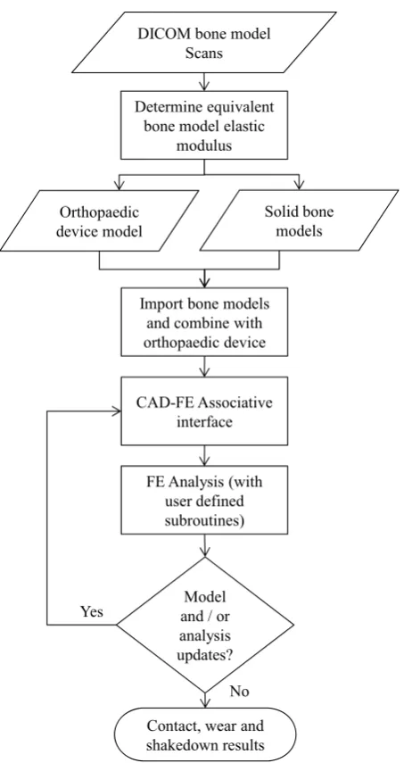
A technique has been developed to take patient bone scans and develop finite element (FE) contact models as described in Fig. 1.
DICOM bone model Scans
Import bone models and combine with orthopaedic device
CAD-FE Associative interface Orthopaedic
device model
FE Analysis (with user defined subroutines)
Model and / or analysis updates?
Contact, wear and shakedown results Yes
No Determine equivalent
bone model elastic modulus
[image:2.595.56.283.237.665.2]Solid bone models
Fig. 1. Bone scans to FE contact models
B. Finite element models
Finite element models were developed in this study which are referred to as models 1-4. The hip resurfacing device was modelled with a bearing diameter (Øf) of 50 mm and diametral clearance (Øc) of 80 µm [16]. To consider worst case conditions and start with a simple contact model, hip
resurfacing components were backed and fully tied to rigid parts (Fig. 2); and elasticity of attached bone was considered for the simulation of models 2-4. For all models, it is assumed that full contact and bonding is maintained between the top surface of the acetabular cup and acetablum and likewise between the bottom surface of the femoral head component and femur. Perfect sphericity of the cup and femoral head were also assumed. For initial conditions the cup and femoral head bearing centres coincide, and all model loads and displacements were subsequently applied within time steps. Both the acetabular cup and femoral head solid models were developed using SolidWorks and all finite element analysis were conducted using ABAQUS (Version 6.10-1).
Microseperation
Fully rigid parts
Femoral head
Acetabular cup
Max. vertical Load (Fy)
µ = 0.16 (coefficient of
friction modelled
between head and cup)
y
[image:2.595.310.521.238.388.2]x z
Fig. 2. Assembly of rigid backed components (model 1)
A vertical load (Fy) of 3900N was applied based on the peak load expected during the walking cycle, however a stumbling load (Fs) of 11000N was also considered, as these high vertical loads have been highlighted to occur [17]. Microseperation was modelled by translating the cup bearing centre in the lateral direction (i.e. along the anatomical lateral-medial axis) as used in experimental testing methods [18] and a finite element study of edge loading [19]. The coefficient of friction (µ) between the head and cup was modelled as 0.16 based on the friction factor of CoCrMo/CoCrMo in both bovine serum and synovial fluid [20]. Of all material combinations studied by Scholes et al. this was the largest friction factor value recorded. The coefficient of friction value modelled in finite element analysis has been shown to have a negligible effect on the contact pressure [16], however, as the surface friction coefficient increases during the life of the component, the subsurface stresses will also increase [21], therefore it has been considered in this study. Meshing techniques were selected based on the geometry of the components and element types were selected appropriately for simulating contact problems.
TABLEI MATERIAL PROPERTIES
Material Elastic modulus Poisson ratio Densityb
CrCrMo 230 0.3 8270
BEF 12.3 0.3 1900
BEP 6.1 0.3 1900
aElastic modulus (GPa), bDensity (kg/m3)
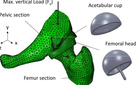
By modelling a section of the femur and pelvis the elasticity of these two parts can be considered (Fig. 3) in the contact analysis. The modelled bone sizes have been checked [26], to ensure the bone models were representative of real specimens. The same modelling approach, loading and boundary conditions from model 1 were considered in models 2-4.
Max. vertical Load (Fy)
Pelvic section
Femur section
Acetabular cup
Femoral head y
[image:3.595.55.285.252.394.2]x z
Fig. 3. Segmented hip joint model (model 2)
A 2D axis symmetric model (Fig 4a) was developed following the model techniques used by Jin et al. [16] as a simple model to conduct a cyclic shakedown analysis. A full hip finite element model (Fig. 4b) has been developed to provide validation for using a segmented model and to provide a more realistic model for central and edge loading conditions.
Femur section Pelvic section
Head Cup Max. vertical Load (Fy)
R Z
Fig. 4. (a) 2D Axis-symmetric model (model 3) and (b) full hip joint model (model 4)
For the application of shakedown theory, elastic-perfectly plastic material properties must be considered. The material considered is ASTM F75 CoCrMo ‘as cast’ material, which is the material choice for the Birmingham Hip Resurfacing
device (BHR). The material properties are adapted [22] to consider an elastic-perfectly plastic material model. For the bone model material an assessment was conducted to find an equivalent bone elastic modulus for the femur (BEF) and pelvis (BEP) as shown in table 1 to provide a simplified material model for the contact analysis. This was obtained by comparing model stiffness of a CT femur and pelvis bone scan loaded in all three directions (x,y,z) to obtain BEF and BEP. This value of elastic modulus offers a bone model stiffness to within 5% of the full bone material model.
By considering the kinematics of the hip joint, it is understood that microseperation leads to edge loading during normal walking gait, and it is claimed that microseperation occurs during the swing phase of gait [27], [28]. The swing phase occurs between 60% and 100% of the gait cycle, where the ball and cup relocate during heel strike and edge loading occurs. As the frequency of the walking cycle ranges from 0.4 - 2.2 Hz [29], it is expected that edge loading could occur over a time period of around 0.5s.
C. Wear increment methodology development
The contact analysis forms a considerable part of simulating the mechanical wear of these devices. Although similar techniques have been applied to study device wear, a methodology was developed to calculate the linear wear at the end of each analysis increment, and the finite element mesh to be updated at the end of every increment. A user defined subroutine has been used to calculate the sliding distance between each increment in the analysis. A method of recording and saving the contact sliding distance during the analysis has also been used and the finite element solver has been used to determine the contact pressures [30]. It is assumed that the wear coefficient obtained experimental, will cover the complex wear mechanisms occurring during the wear process. The numerical methodology has been developed to allow for the variations in wear rates to be considered by setting the dimensional wear coefficient values at cyclic points in during the analysis (i.e. bedding-in phase).
D. Theoretical contact and microseperation models
The finite element model was validated against theoretical calculations under centred/normal loading conditions. These calculations were based on Hertz contact theory derived as shown in (2) and (3) [16] to calculate the contact radius (b) and maximum contact stress (σc), where
R, ν and E are the effective radius, Poisson’s ratio and
modulus of elasticity respectively.
3
2
2 1 3 [
E R F
b y (2)
2
2 3
b Fy
c
(3)
To understand and define the distance for onset of rim contact (s) an equation has been derived by Mak et al. (4), where θ is the cup inclination angle and c is the bearing
radial clearance. This equation shows that if the microseperation distance exceeds Øc for a cup inclination angle of 45º, then this will lead to contact between the edge of the cup and femoral head (i.e. edge contact). [31]
c
s
tan 1
1 (4)
III. RESULTS
A. Model 1: Rigid backed model
[image:4.595.314.541.167.325.2]Based on the walking gait peak vertical load of 3900 N the maximum contact pressure was 101 MPa without consideration of microseperation. The contact pressure increased to a maximum of 1284 MPa (Fig. 5) respectively when 250 μm of lateral displacement was applied in combination with the peak load as shown above the rim of the acetabular cup. By considering a lateral reaction force of 500N (in line with experimental simulator test methods) without any vertical load led to a maximum contact pressure of 564 MPa, von Mises stress of 456 MPa and maximum principal stress of 431 MPa.
Fig. 5. Rigid backed edge loading contact pressure distribution
The simulation conducted on this model considered one cycle of edge loading, however edge loading could occur in a cyclic manner. When the edge load was removed (i.e. contact removed) plastic strain was predicted to be negligible. Through the assessments of the subsurface stresses in the edge loaded region it was found that the maximum stress occurred at the subsurface (Fig. 6.)
Fig. 6. Edge loaded subsurface strain location
B. Model 2-3: Segmented and full hip joint model
For model 2, the reaction forces were checked to ensure 3900 N was applied in the vertical direction. It was also noted that a 250 µm translation in the lateral direction led to an edge loading reaction force of 907 N. Based on the walking gait peak vertical load of 3900 N the maximum contact pressure was 18 MPa without consideration of microseperation (Fig. 7a). The contact pressure (Fig. 7b.) and von Mises stress increased to a maximum of 142 MPa and 141 MPa respectively when microseperation conditions
were applied in combination with the peak load as shown on the edge of the acetabular cup. The results obtained from the full hip model, showed maximum contact pressure under normal loading conditions to be 17MPa, which match closely the results obtained for model 2. By conducting analysis using the full hip model, edge loaded regions and high contact pressures are less prominently observed in the results.
Fig. 7. (a) Centrally loaded contact distribution (b) edge loaded contact pressure distribution of model 2.
By comparing the maximum stresses and stress distributions between model 1 and model 2-3 the effects of modelling strategy can be observed. The contact patch for edge loaded acetabular cups and femoral heads were noted to be elliptical (with a high b/a ratio) compared with a circular contact area for centrally loaded cups and heads. The total contact area for centrally loaded contact and edge loading contact has been provided in Fig. 8.
0 50 100 150 200 250 300 350
1 1.5 2 2.5 3
Co
n
ta
ct
Ar
e
a
(m
m
^
2
)
[image:4.595.45.287.337.408.2]Time Step (s)
Fig 8. Total contact area between the femoral head and acetabular cup (a) normal contact conditions (b) edge loading rim contact.
C. Shakedown assessment (all models)
Based on shakedown maps for line and circular contact [7], [8] and a friction coefficient of 0.16 the component will remain in an elastic state under contact loading as long as the load intensity Po/k does not exceed 3 (Fig. 9.), where Po and k are the maximum contact pressure and material shear yield strength respectively. The value of k (5) was calculated based on the definition of this calculating this value in literature [8]. Based on theoretical shakedown maps and considering the maximum contact pressure observed,
Normal contact conditions Edge loading
a
b
Contact pressure (MPa)
Max. Contact pressure = 142 MPa
Contact pressure (MPa) Max.
Contact pressure = 18 MPa
[image:4.595.310.543.471.624.2] [image:4.595.47.289.534.634.2]the load intensity Po/k is predicted to lie within the elastic region of the shakedown map and does not fall within the predicted elastic shakedown regions of the shakedown maps. By conducting the 2D axis-symmetric cyclic analysis using model 4, the stress-strain curve predicts the hip resurfacing device material to remain within the elastic region under normal loading conditions.
y
k 3 (5)
L
oa
d in
te
ns
ity
Po
/k
Coefficient of friction µ
1
0 2 3 4
5
0.1 0.2 0.3 0.4 0.5
Elastic region
[image:5.595.55.282.147.397.2]Elastic-perfectly plastic shakedown limit Elastic shakedown region
Figure 9. Shakedown map representation for line contact [7]
IV. DISCUSSION
By comparing the results obtained for all computational models the effect of bone elasticity on the contact pressure and von Mises stress distributions is shown. Any asymmetrical contact and stress distributions are predicted to be caused by unsymmetrical geometry of the human anatomy. When considering microseperation conditions, it was observed that the maximum contact pressure and von Mises stress is observed towards the anterior end of the acetabular cup (Fig. 7b.). For all three dimensional models, the plastic strains and stress were found to be above the rim radius of the cup as inspected from patient retrievals and experimental simulations which consider microseperation conditions. The corresponding contact on the femoral head component is also dependant upon the anteversion angle of the implanted cup.
The magnitude of stresses and contact pressures observed may appear large for model 1 however, the rigidity of backing components have shown to increase the results by at least a factor of 5 over the results obtained using models 2-4. These high levels of contact pressure and stress have also been observed by Mak et al. [19]. The maximum stress and therefore plastic strain (Fig. 6.) was observed below the surface of the material as predicted by Hertz theory for surfaces in contact with a coefficient less than 0.3. For model 1, the total contact area under edge loading conditions was 2.7 times less than under central/normal contact conditions (Fig. 8.). This is an important finding as
the contact patch dimensions directly affects the linear wear as does the contact pressure according to the Archard wear model used to study wear of the bearing surfaces. The Archard wear model in combination with the FE solver, provides a basis for modelling the wear of the bearing surfaces. No plasticity was observed in models 2-4, therefore, in reality it is predicted that material plasticity will not occur under normal and edge loading conditions.
Although fatigue assessments are an important consideration for any cyclically loaded component, through this study it is deemed that fatigue strength along with fracture toughness of Cobalt Chromium are significantly larger than bone. The fracture toughness of cobalt-chromium-molybdenum (CoCrMo) could be up to 50 times greater than for bone [32]. This high fracture toughness would much sooner cause femoral neck fracture [33], [34] before fracture or fatigue failure of the metal-on-metal device.
The microseperation distance of 250 µm (to a maximum of 500 µm) was equivalent to a force greater than that considered in experimental simulator studies which is typically 200 N to 500 N in magnitude. It was possible to assess the reaction forces in the edge loaded regions to determine the contact results at specific loading magnitudes. This observation also explains the high values of edge loading contact pressure observed in model 1. Based on the maximum contact pressure and calculated value of k, a low value of load intensity, suggests that the component under central and edge loading conditions will remain within the elastic region of a contact shakedown map, which is a ‘safe’ region for the component to be operating in. Therefore, in terms of the hip resurfacing devices response to loading, elastic shakedown, plastic shakedown or ratcheting behaviour is unlikely to be observed, during normal contact conditions or edge loading conditions.
V. CONCLUSION
In this study modelling verification, comparative solutions to other studies and theoretical models have been developed for centred contact conditions; however, further work is required to develop theoretical and computational models to more accurately simulate and assess the affects of edge loading and microseperation on hip resurfacing devices. The kinematics of these conditions during human joint motion should be considered in more depth if simulations are to more accurately model these problems. Overall, using a combination of techniques and theory has shown to be beneficial in developing the simulations to hip resurfacing devices under specific conditions.
ACKNOWLEDGMENT
We would like to acknowledge the help and support of the BioMed Town team and community. We would also like to thank the research team at Smith and Nephew Orthopaedics Ltd for their support and advice.
REFERENCES
[1] J. G. Bowsher, T. K. Donaldson, P. A. Williams, and I. C. Clarke, "Surface Damage After Multiple Dislocations of a 38-mm-Diameter, Metal-on-Metal Hip Prosthesis," Journal of Arthroplasty, vol. 23, pp. 1090-1096, Oct 2008.
[2] W. L. Walter, G. M. Insley, W. K. Walter, and M. A. Tuke, "Edge loading in third generation alumina ceramic-on-ceramic bearings," Journal of Arthroplasty, vol. 19, pp. 402-413, Jun 2004.
[3] S. Williams, T. D. Stewart, E. Ingham, M. H. Stone, and J. Fisher, "Metal-on-metal bearing wear with different swing phase loads," Journal of Biomedical Materials Research Part B-Applied Biomaterials, vol. 70B, pp. 233-239, Aug 2004.
[4] M. Manaka, I. C. Clarke, K. Yamamoto, T. Shishido, A. Gustafson, and A. Imakiire, "Stripe wear rates in alumina THR - Comparison of microseparation simulator study with retrieved implants," Journal of Biomedical Materials Research Part B-Applied Biomaterials, vol. 69B, pp. 149-157, May 2004.
[5] I. J. Leslie, S. Williams, G. Isaac, E. Ingham, and J. Fisher, "High Cup Angle and Microseparation Increase the Wear of Hip Surface Replacements," Clinical Orthopaedics and Related Research, vol. 467, pp. 2259-2265, 2009.
[6] R. A. Poggie, T. R. Turgeon, and R. D. Coutts, "Failure analysis of a ceramic bearing acetabular component," Journal of Bone and Joint Surgery-American Volume, vol. 89A, pp. 367-375, Feb 2007. [7] J. A. Williams, "The influence of repeated loading, residual stresses
and shakedown on the behaviour of tribological contacts," Tribology International, vol. 38, pp. 786-797, 2005.
[8] A. R. S. Ponter, H. F. Chen, M. Ciavarella, and G. Specchia, "Shakedown analyses for rolling and sliding contact problems," International Journal of Solids and Structures, vol. 43, pp. 4201-4219, 2006.
[9] J. A. Williams, I. N. Dyson, and A. Kapoor, "Repeated loading, residual stresses, shakedown, and tribology," Journal of Materials Research, vol. 14, pp. 1548-1559, Apr 1999.
[10] T. Tateiwa, I. C. Clarke, G. Pezzotti, L. Sedel, T. Kumakura, T. Shishido, and K. Yamamoto, "Surface micro-analyses of long-term worn retrieved "Osteal (TM)" alumina ceramic total hip replacement," Journal of Biomedical Materials Research Part B-Applied Biomaterials, vol. 83B, pp. 562-570, Nov 2007.
[11] S. Williams, A. Schepers, G. Isaac, C. Hardaker, E. Ingham, D. van der Jagt, A. Breckon, and J. Fisher, "The 2007 Otto Aufranc Award - Ceramic-on-metal hip arthroplasties - A comparative in vitro and in vivo study," Clinical Orthopaedics and Related Research, pp. 23-32, Dec 2007.
[12] R. Pourzal, R. Theissmann, S. Williams, B. Gleising, J. Fisher, and A. Fischer, "Subsurface changes of a MoM hip implant below different contact zones," Journal of the Mechanical Behavior of Biomedical Materials, vol. 2, pp. 186-191, Apr 2009.
[13] J. F. Archard, "Contact and Rubbing of Flat Surfaces," Journal of Applied Physics, vol. 24, pp. 981-988, 1953.
[14] T. A. Maxian, T. D. Brown, D. R. Pedersen, and J. J. Callaghan, "A sliding-distance-coupled finite element formulation for polyethylene wear in total hip arthroplasty," Journal of Biomechanics, vol. 29, pp. 687-692, 1996.
[15] S. K. Wong, A. Kapoor, and J. A. Williams, "Shakedown limits on coated surfaces," Thin Solid Films, vol. 292, pp. 156-163, 1997. [16] I. J. Udofia, A. Yew, and Z. M. Jin, "Contact mechanics analysis of
metal-on-metal hip resurfacing prostheses," Proceedings of the Institution of Mechanical Engineers Part H-Journal of Engineering in Medicine, vol. 218, pp. 293-305, 2004.
[17] G. Bergmann, F. Graichen, A. Rohlmann, A. Bender, B. Heinlein, G. N. Duda, M. O. Heller, and M. M. Morlock, "Realistic loads for testing hip implants," Bio-Medical Materials and Engineering, vol. 20, pp. 65-75, 2010.
[18] T. Stewart, J. Tipper, R. Streicher, E. Ingham, and J. Fisher, "Long-term wear of HIPed alumina on alumina bearings for THR under microseparation conditions," Journal of Materials Science-Materials in Medicine, vol. 12, pp. 1053-1056, 2001.
[19] M. Mak, Z. Jin, J. Fisher, and T. D. Stewart, "Influence of Acetabular Cup Rim Design on the Contact Stress During Edge Loading in Ceramic-on-Ceramic Hip Prostheses," The Journal of Arthroplasty, vol. 26, pp. 131-136, 2011.
[20] S. C. Scholes, A. Unsworth, and A. A. J. Goldsmith, "A frictional study of total hip joint replacements," Physics in Medicine and Biology, vol. 45, pp. 3721-3735, Dec 2000.
[21] J. Farley, "Development of a Computational Method of Low Cycle Fatigue Prediction for Multi-Layer Surfaces under Rolling/Sliding Conatact Conditions," Doctor of Philosophy, School of Engineering and Design, Brunel University, 2008.
[22] Materials and Coatings for Medical Devices: Cardiovascular: ASM International, 2009.
[23] Y. Zait, V. Zolotarevsky, Y. Kligerman, and I. Etsion, "Multiple Normal Loading-Unloading Cycles of a Spherical Contact Under Stick Contact Condition," Journal of Tribology-Transactions of the Asme, vol. 132, p. 7, Oct 2010.
[24] R. Hodgskinson and J. D. Currey, "Young modulus, density and material properties in cancellous bone over a large density range," Journal of Materials Science-Materials in Medicine, vol. 3, pp. 377-381, 1992.
[25] M. Dalstra, R. Huiskes, and L. Vanerning, "Development and validation of a 3-dimensional finite-element model of the pelvis bone," Journal of Biomechanical Engineering-Transactions of the Asme, vol. 117, pp. 272-278, 1995.
[26] D. G. Steele and C. A. Bramblett, The Anatomy and Biology of the Human Skeleton: Texas A&M University Press, 1988.
[27] A. V. Lombardi, T. H. Mallory, D. A. Dennis, R. D. Komistek, R. A. Fada, and E. J. Northcut, "An in vivo determination of total hip arthroplasty pistoning during activity," Journal of Arthroplasty, vol. 15, pp. 702-709, Sep 2000.
[28] D. A. Dennis, R. D. Komistek, E. J. Northcut, J. A. Ochoa, and A. Ritchie, ""In vivo" determination of hip joint separation and the forces generated due to impact loading conditions," Journal of Biomechanics, vol. 34, pp. 623-629, 2001.
[29] S. Affatato, A. Spinelli, M. Zavalloni, C. Mazzega-Fabbro, and A. Viceconti, "Tribology and total hip joint replacement: Current concepts in mechanical simulation," Medical Engineering & Physics, vol. 30, pp. 1305-1317, Dec 2008.
[30] D. Sheeja, B. K. Tay, S. P. Lau, and L. N. Nung, "Tribological characterisation of diamond-like carbon coatings on Co–Cr–Mo alloy for orthopaedic applications," Surface and Coatings Technology, vol. 146–147, pp. 410-416, 2001.
[31] M. M. Mak, A. A. Besong, Z. M. Jin, and J. Fisher, "Effect of microseparation on contact mechanics in ceramic-on-ceramic hip joint replacements," Proceedings of the Institution of Mechanical Engineers Part H-Journal of Engineering in Medicine, vol. 216, pp. 403-408, 2002.
[32] R. E. Smallman and R. J. Bishop, "Modern Physical Metallurgy and Materials Engineering - Science, Process, Applications (6th Edition)," ed: Elsevier, 1999.
[33] H. Sharma, B. Rana, C. Watson, A. Campbell, and B. Singh, "Femoral neck fractures complicating metal-on-metal resurfaced hips: a report of 2 cases," Journal of Orthopaedic Surgery 2005;13(1):69-72, 2005.

![Figure 9. Shakedown map representation for line contact [7]](https://thumb-us.123doks.com/thumbv2/123dok_us/1283077.656919/5.595.55.282.147.397/figure-shakedown-map-representation-line-contact.webp)
