Abstract— Carbon nanospheres have been synthesized using coconut fibre as a renewable feedstock in a three step process which involves pyrolyzation, physical activation and ethanol vapour treatment. The synthesis method produced nanomaterials consisting of nanospheres which have been analysed using field emission scanning electron microscope (FESEM), transmission electron microscopy (TEM), energy dispersive X-ray spectroscopy (EDX), powder x-ray diffraction (p-XRD), fourier transform infra-red spectroscopy (FTIR) and thermogravimetric analysis (TGA). Scanning Electron Microscope (SEM) investigations confirm the production of carbon nanospheres with diameter between 30nm-150nm. The synthesized carbon nanospheres can be used as base particles in nanofluids, in lithium-ion batteries and in the medical field for drug delivery.
Index Terms—
,
Bio-based feedstock, carbon nanospheres, coconut fibre, low-cost synthesis.I. INTRODUCTION
NNUALLY, 12,280 hectares of land are cultivated for coconut trees, from which 64.3 billion nuts are harvested [1]. Fibres from coconut have the highest ductility compared to other fibres obtained from vegetation sources as they have the capability of taking 4-6 times of their strain which is more than that of other fibres comprising of cellulose, hemi cellulose and lignin as major composition [2]. Coconut fibre (CF) is obtained from the pericarp of coconut fruit and a coconut is made up of 33 to 35% of husk. Presently, CF are being used as fuel in the processing of coconut-based products, as a fibre source for manufacturing ropes and mats and as a fuel for domestic application [3]. To benefit from this plentiful and low-cost agricultural waste, coconut fibre has been transformed into a carbon nanomaterial. The conversion of CF into carbon nanomaterials will function as an important raw material
Manuscript received June 22, 2017; revised June, 2017. This work was supported in part by the National Research Foundation South under Grant 109819.
G.A. Adewumi is a Doctoral candidate at the University of KwaZulu-Natal, South Africa. She is with the Mechanical Engineering Department (phone:+27749423154; e-mail: [email protected]).
N. Revaprasadu is with the University of Zululand X1001, Kwadlangezwa 3886, South Africa (e-mail: [email protected]).
A.C Eloka-Eboka is a Postdoctoral Fellow at the University of KwaZulu-Natal, South Africa. Dr. Eloka-Eboka is with the Mechanical Engineering Department of the (e-mail: [email protected]).
F.L. Inambao is a Professor in Mechanical Engineering at the University of KwaZulu-Natal South Africa (e-mail [email protected]).
C. Gervas is a Doctoral fellow in Chemistry Department at the University of Zululand X1001, Kwadlangezwa 3886, South Africa (e-mail
obtained from agricultural waste. Carbon is a group 14 element that is distributed very widely in nature. It also has a remarkable ability to bond with several other elements as a result of its polyvalent properties. The three allotropes of carbon are amorphous, diamond and graphite which occur naturally. Recent research has tuned carbon into nanoscale, resulting into carbon nanotubes, carbon nanofibers and carbon nanospheres.
Carbon has the remarkable capability to bond in several exceptional ways thereby creating structures with distinct properties. This can be seen in the filament-like arrangement of graphene sheets corresponding to carbon nanotubes (CNTs) and carbon nanofibres (CNFs). Heptagonal and in pentagonal pairing of carbon atoms can result in the creation of carbon nanospheres. The graphite sheets in nanospheres occur as waving flakes instead of closed shells which takes the form of the sphere, hence having several open ends at the surface and establishing carbon nanospheres (CNS) as suitable materials for catalytic and adsorption application [4].
Laboratory fabrication of carbon nanospheres involve methods such as chemical vapour deposition (CVD) [5-8], hydrothermal treatment [9], pyrolysis of polymers [10], ultrasonic treatments and chlorination of cobaltocene [11]. Generally, chemical vapour deposition (CVD) occurs when rare earth metal oxides or metal oxides are used as catalysts which results in a need for purification of the synthesized carbon spheres in order to get rid of the catalyst. This makes the process limited to a small scale [12]. Various sources of biomass are being used for the production of nanomaterials derived from carbon [13, 14] because of their low toxicity and availability. These biomasses are often first carbonized, and then activated before being converted to carbon nanomaterials using different methods [15-20]. The method of activation used can either be physical (thermal), chemical or a combination of both physical and chemical processes [3]. The physical process involves the use of CO2, steam or air and takes place at higher temperatures while the chemical process which is one-step, takes place at lower temperatures and involves the co-carbonization of a parent feedstock with a suitable chemical compound. Three chemicals, which have been frequently used, include zinc chloride, phosphoric acid and potassium hydroxide or potassium carbonate. Even though any carbon rich material can be used to produce activated carbon, the bio-mass precursor to be used has to possess factors like reliability and consistency in order to be considered sustainable [21].
A study was carried out on natural sources by Kumar et al. [22] as a means of synthesizing carbon nanomaterials. The study revealed the use of fossil hydrocarbons, waste natural products natural and botanical hydrocarbon
A Facile Low-cost Synthesis of Carbon
Nanosphere from Coconut Fibre
Gloria A. Adewumi,
Member, IAENG,
Neerish Revaprasadu, Andrew C. Eloka-Eboka,
Member,
IAENG,
Freddie L. Inambao and Charles Gervas
precursors as sources of hydrocarbon for CNT and graphene synthesis. Those based on fossil hydrocarbon are mostly costly and not readily accessible. In addition, a lot of the liquid and gaseous fossil hydrocarbons are explosive or toxic in nature and are not acceptable for both atmospheric and human health. On the other hand, carbon nanomaterials derived from carbon based natural precursors have the advantage of producing scalable amounts, they are safe to use in the environment, cheap and allows for fast production techniques. Activated carbon has been prepared from oil palm fibre and oil palm shell [23] using physical activation process. The process was optimized by adjusting retention time and CO2 conditions (activation temperature, flow rate). Tan et al. [3] prepared activated carbon from coconut fibre using a complexion of physical and chemical methods of activation made up of carbon dioxide (CO2) gasification and potassium hydroxide (KOH) treatment. The rate of reaction between carbon [24] and carbon dioxide was inhibited by the reaction products of hydrogen and carbon monoxide. The mechanism is as follows [21, 25]:
Initially, a surface oxygen complex (C(O)) is formed, which afterwards acquires some stability under the conditions of reaction:
In this study, the authors present the results from the green synthesis and characterization of carbon nanospheres from coconut fibre biomass using a scalable, time efficient (210 mins) and cost effective process. The materials were synthesized from agricultural waste in the absence of catalysts and acids. The production of the nanospheres involved a three step technique which consists of pyrolyzation, physical activation and ethanol vapour treatment at high temperature followed by characterization using SEM, TEM, EDX, FTIR, TGA and XRD. The produced nanomaterial can be applied in thermal applications for the enhancement of heat transfer working fluids, lithium-ion battery and medical drug delivery.
II. EXPERIMENTAL METHOD
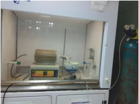
Coconut fibre used in the study was purchased from farmers in a local market in Nigeria and taken to South Africa for research studies. It was received in fibre form and was first washed then dried to reduce moisture content after which it was cut with scissors to size ranges of about 1 mm. Both carbonization in an inert atmosphere and physical activation were carried out in a heat resistant quartz tube (maximum temperature: 1200oC) which was placed into a horizontal tube furnace (Carbolite furnace type MTF 12/25/250, Parsons Lane, with maximum temperature of 1200oC at 700 watts, 50-60 Hertz and 220 volts ). Some 14.0 g of the dried specimens were put in a quartz tube, and then placed in the centre of the horizontal tube furnace (Fig. 1). While pyrolysis was ongoing, pure
nitrogen gas at a flow rate of 80 scfm-1 was used as purge gas and introduced into the system at one end. The other end of the tube was exhausted into a beaker of water. The temperature of the furnace was elevated from 25 to 600oC and held for 2 h. The resulting char was physically activated at 800oC for 30 mins under CO2 gas. A heating rate of 60oC/min was used.
[image:2.595.304.548.242.425.2]The activated carbon obtained above was inserted into a tube placed in a tube furnace, flushed with argon gas and heated at a temperature of 1100°C at 60°C min−1 for 1hr. At a desired target temperature, 75.0 mL of argon gas passing through a flask of ethanol vapour placed on an ultrasonic humidifier (99.9 %) was introduced into the system. After 60 min treatment, the system was allowed to cool down at a rate of 5 °C min−1 under the flow of argon gas.
Fig. 1. Experimental setup
A. Material characterization
directly dispersed in 95% ethanol directly. After being sonicated for 15 minutes, the samples were placed onto carbon coated copper grids and dried for TEM investigation. The FTIR was analysed using a Perkin Elmer Product FT-IR Spectrum 100 Series while for thermal gravimetric analysis (TGA), simultaneous thermal analyzer (STA) 6000 | PerkinElmer was used.
III. RESULTS AND DISCUSSSION A. Particle Size Distribution and Morphology
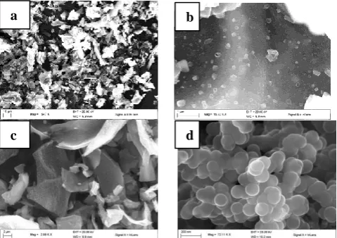
Fig. 2 shows a histogram which analyses the size distribution of the nanospheres synthesized. The nanospheres are in the size range of 10 -150 nm and the size with the highest occurrence is 60-89 nm. From the fig., nanospheres of diameter in the range 60-89 nm constituted almost 50% (48.5%) while nanospheres of diameter 30-59 nm constituted 41%. This shows uniformity in the size range of the nanospheres. In the process of carbonization, porosity begins to develop at 600 oC; however the porosity is irregular and not defined. Fig. 3 depicts some typical SEM images of the carbonized coconut fibre at 600 oC for 2hrs. In order to increase porosity, the pyrolyzed coconut fibre was activated under CO2 for 30 mins. Fig. 3c shows the SEM image of coconut fibre charcoal after being physically activated which indicates some porosity.
The morphology obtained from SEM analysis of the as-synthesized nanospheres is shown in Fig. 3d. The morphology indicates agglomeration between the particles which is as a result of the high surface energy present. The TEM image obtained shows solid nanospheres of high purity graphite as shown in Fig. 4. The particle size obtained agrees with that obtained from the SEM analysis (30-100 nm). TEM and SEM images show mono-dispersed carbon nanospheres without impurities. These carbon nanospheres have diameters of 30-150 nm. More than 80% of the carbon nanospheres have sizes in the range of 30-100 nm. Fig. 3a-d shows the SEM images carbonized material, activated carbon and synthesized carbon nanomaterial. Fig. 4 shows TEM image of the as-synthesized CNS which is in correlation with SEM results. Observations show that the
CNS are perfect spheres with smooth surfaces. Several agglomerates of the spheres and also bead-like accretions are present in both SEM and TEM. The size distribution obtained from the CNS obtained makes them a potential candidate for biomedical applications [26] and for use in heat transfer applications when dispersed in working fluids for enhanced thermal conductivity [27].
Fig. 3. (a and b) SEM images of carbonized coconut fibre at 600oC under different magnifications. (c) SEM image of activated carbon, physically activated under CO2 for 30 mins at 800oC (d) SEM image of carbon nanosphere at 1100oC under ethanol vapour
Fig. 4. (a): TEM image of carbonized coconut fibre (b) TEM image of as-synthesized carbon nanospheres.
B. Elemental Composition Analysis
The elemental composition of carbonized coconut fibre, activated carbon and CNS synthesized over ethanol vapour was revealed by EDX analysis shown in Fig 5a-5c. Carbonized coconut fibre contains mostly carbon (87.80%), oxygen (9.66%), magnesium (0.15%), chlorine (0.48%), and potassium (1.91%). Activated carbon elemental analysis contains carbon (87.40%), oxygen (5.36%) and other materials in trace quantities. The elemental composition of CNS has 98.59 % of carbon which confirms the purity of the nanomaterials produced. These results prove that treatment with ethanol vapour at 1100 oC formed well rounded carbon nanospheres. Table 1 shows elemental composition of carbonized CF, activated ACF and CNS. Decrease in oxygen is due to the rise in temperature from 600 oC for carbonized CF to 800 oC for activated CF and finally 1100oC for nanosphere production. The increase in temperature results in oxygen removal and an increment value of carbon.
0-29 30-59 60-89 90-119 120-149
0 10 20 30 40 50
F
req
u
en
cy
(
%)
[image:3.595.305.545.144.313.2]Diameter (nm)
Fig. 2. Nanosphere particle size distribution
a b
c d
[image:3.595.306.548.362.476.2] [image:3.595.43.293.556.729.2]Fig. 5. (a) EDX of carbonized coconut fibre at 600 oC (b) EDX of coconut fibre activated carbon (c) EDX of CNS
C. Structural Analysis
The crystallinity and graphitization degree is studied using XRD analysis. Fig. 6 presents the XRD pattern in which the two Bragg diffraction peaks at 30.34o and 50.44o can be assigned as typical graphite (003) and (101) planes [28]. The d-spacing calculated is 0.342 nm which is close to graphite 3R given as 0.340 nm. The broadening peaks suggest a low graphitization degree and the possibility of the presence of amorphous carbon. These results fall in the range of authors [24] and [29] with d-spacing of 0.33nm and 0.36 nm respectively No other peaks of are visible in the XRD pattern, which could be due to the high purity of the product. Fig. 5 confirms the purity of the material with a well-defined presence of carbon (98.59%).
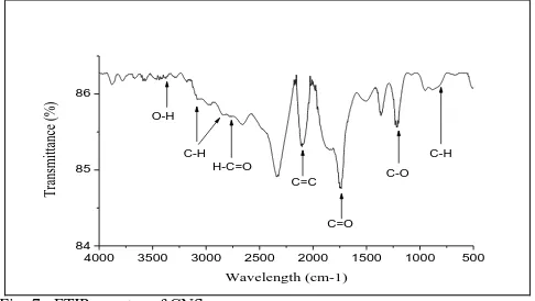
The functional groups present in the carbon nanospheres synthesized were analyzed using FTIR analysis (Fig. 7). A peak at 3437 cm-1 can be assigned to the O-H stretching vibrations including hydroxyl functional group [30]. 2787 cm-1 to O-H acids, 2100 cm-1 to C=C stretching in alkyne, the peaks at 1798 to the stretching vibration of C=O in carboxyl group [31] and 1743 can be attributed to C=C stretching vibrations. At 1210 cm-1 the vibration can be assigned to C-C bond. The aromatic C-H bend at 805 cm-1 suggests the presence of aromatic ring [32] while the unsaturated C=C groups indicates that a carbonization and
activation process occurred while the presence of a hydroxyl group improves the rate of hydrophobicity and stability of the CNS in aqueous solution.
20 40 60
200 400 600 800 1000 1200 1400
In
te
n
si
ty
(C
o
u
n
ts)
2theta (Degree) 30.34
50.44
[image:4.595.313.550.82.139.2]
Fig. 6. XRD pattern of carbon nanospheres synthesized at 1100 oC
4000 3500 3000 2500 2000 1500 1000 500
84 85 86
Transmittance (%)
Wavelength (cm-1)
C-H O-H
C=O C-O
C-H
C=C H-C=O
Fig. 7. FTIR spectra of CNS
IV. THERMAL STABILITY
The thermal stability of the material was studied through TGA in Fig. 8. The curve shows a single decomposition phase between 350oC and 1000oC. The curve shows that the material is fairly stable in an inert atmosphere with a small weight loss of about 5% which can be seen before 350oC. This could be as a result of loss in moisture in the sample. At about 400oC, there is a sharp slope which may indicate the presence of lattice defects that enables oxygen to rapidly pass through the spheres thereby facilitating rapid oxidation. The samples are entirely burnt off at 1000oC.
V. CONCLUSION
A general time effective and cost effective strategy has been adopted for preparing carbon nanospheres from coconut fibre bio-based feedstock. This method is not only cheap, but non-toxic and sustainable. The synthesis method involves carbonizing, followed by physical activation and a
b
c
TABLEI
ELEMENTAL COMPOSITION OF CARBONIZED CF,ACTIVATED CF AND
CNS
Carbonized
CF Activated CF CNS
Carbon 87.80% 87.40% 98.59%
[image:4.595.305.545.199.371.2] [image:4.595.305.548.408.545.2]0 200 400 600 800 1000 -20 0 20 40 60 80 100 Wei g h t (%) Temperature (oC)
Fig. 8. TGA curve of as-synthesized carbon nanospheres
finally passing ethanol vapour through the activated carbon obtained. The carbonized coconut fibre and carbon nanospheres formation was investigated through XRD, SEM, TEM, EDX, FTIR and TGA analysis. SEM investigations confirms the production of carbon nanospheres with diameters between 30-150nm. The observations also show that the CNS are perfect spheres with smooth surfaces. Multiple conglomerates of the spheres are observed and also bead-like lumps are observed in both SEM and TEM. The nanosphere obtained can be used in Lithium-ion batteries, heat transfer fluids and medical field for drug delivery.
ACKNOWLEDGMENT
The financial assistance of the National Research Foundation (NRF) towards this research is hereby acknowledged. Opinions expressed and conclusions arrived at, are those of the author and are not necessarily to be attributed to the NRF.
REFERENCES
[1] S. A. Bello, J. O. Agunsoye, J. A. Adebisi, F. O. Kolawole, and S. B. Hassan, "Properties of coconut shell nanoparticles,"
Journal of Science, Engineering and Technology, vol. 12, pp. 63-79, June 2016 2016.
[2] M. Ali, "Coconut fibre: A versatile material and its applications in engineering," Journal of Civil Engineering and Construction Technology, vol. 2, pp. 189-197, 2011.
[3] I. Tan, A. Ahmad, and B. Hameed, "Preparation of activated carbon from coconut husk: optimization study on removal of 2, 4, 6-trichlorophenol using response surface methodology,"
Journal of hazardous materials, vol. 153, pp. 709-717, 2008. [4] A. Nieto-Márquez, R. Romero, A. Romero, and J. L. Valverde,
"Carbon nanospheres: synthesis, physicochemical properties and applications," Journal of Materials chemistry, vol. 21, pp. 1664-1672, 2011.
[5] H.-s. Qian, F.-m. Han, B. Zhang, Y.-c. Guo, J. Yue, and B.-x. Peng, "Non-catalytic CVD preparation of carbon spheres with a specific size," Carbon, vol. 42, pp. 761-766, 2004.
[6] Y. Z. Jin, C. Gao, W. K. Hsu, Y. Zhu, A. Huczko, M. Bystrzejewski, et al., "Large-scale synthesis and characterization of carbon spheres prepared by direct pyrolysis of hydrocarbons," Carbon, vol. 43, pp. 1944-1953, 2005. [7] J.-Y. Miao, D. W. Hwang, K. V. Narasimhulu, P.-I. Lin, Y.-T.
Chen, S.-H. Lin, et al., "Synthesis and properties of carbon nanospheres grown by CVD using Kaolin supported transition metal catalysts," Carbon, vol. 42, pp. 813-822, 2004.
[8] M. Ibrahim Mohammed, R. Ismaeel Ibrahim, L. H. Mahmoud, M. A. Zablouk, N. Manweel, and A. Mahmoud, "Characteristics of carbon nanospheres prepared from locally deoiled asphalt,"
Advances in Materials Science and Engineering, vol. 2013, 2013.
[9] X. Yu, J. Lu, C. Zhan, R. Lv, Q. Liang, Z.-H. Huang, et al., "Synthesis of activated carbon nanospheres with hierarchical porous structure for high volumetric performance supercapacitors," Electrochimica Acta, vol. 182, pp. 908-916, 2015.
[10] Y. Wang, F. Su, C. D. Wood, J. Y. Lee, and X. S. Zhao, "Preparation and characterization of carbon nanospheres as anode materials in lithium-ion secondary batteries," Industrial & Engineering Chemistry Research, vol. 47, pp. 2294-2300, 2008.
[11] N. Katcho, P. Zetterström, E. Lomba, J. Marco, E. Urones-Garrote, D. Avila-Brande, et al., "Structure of carbon nanospheres prepared by chlorination of cobaltocene: Experiment and modeling," Physical Review B, vol. 77, p. 195402, 2008.
[12] P. Zhang, Z.-A. Qiao, and S. Dai, "Recent advances in carbon nanospheres: synthetic routes and applications," Chemical Communications, vol. 51, pp. 9246-9256, 2015.
[13] A. A. Arie, H. Kristianto, M. Halim, and J.-K. Lee, "Biomass Based Carbon Nanospheres as Electrode Materials in Lithium Ion Batteries," ECS Transactions, vol. 66, pp. 13-19, 2015. [14] H. Kristianto, C. D. Putra, A. A. Arie, M. Halim, and J. K. Lee,
"Synthesis and Characterization of Carbon Nanospheres Using Cooking Palm Oil as Natural Precursors onto Activated Carbon Support," Procedia Chemistry, vol. 16, pp. 328-333, 2015. [15] X.-W. Chen, O. Timpe, S. B. Hamid, R. Schlögl, and D. S. Su,
"Direct synthesis of carbon nanofibers on modified biomass-derived activated carbon," Carbon, vol. 47, pp. 340-343, 2009. [16] J. Zhu, J. Jia, F. L. Kwong, D. H. L. Ng, and S. C. Tjong,
"Synthesis of multiwalled carbon nanotubes from bamboo charcoal and the roles of minerals on their growth," biomass and bioenergy, vol. 36, pp. 12-19, 2012.
[17] H. Li, X. He, Y. Liu, H. Yu, Z. Kang, and S.-T. Lee, "Synthesis of fluorescent carbon nanoparticles directly from active carbon via a one-step ultrasonic treatment," Materials Research Bulletin, vol. 46, pp. 147-151, 2011.
[18] J. O. Alves, C. Zhuo, Y. A. Levendis, and J. A. Tenório, "Catalytic conversion of wastes from the bioethanol production into carbon nanomaterials," Applied Catalysis B: Environmental, vol. 106, pp. 433-444, 2011.
[19] K. Shi, J. Yan, E. Lester, and T. Wu, "Catalyst-Free Synthesis of Multiwalled Carbon Nanotubes via Microwave-Induced Processing of Biomass," Industrial & Engineering Chemistry Research, vol. 53, pp. 15012-15019, 2014.
[20] A. Melati and E. Hidayati, "Synthesis and characterization of carbon nanotube from coconut shells activated carbon," in
Journal of Physics: Conference Series, 2016, p. 012073. [21] H. Marsh and F. R. Reinoso, Activated carbon: Elsevier, 2006. [22] R. Kumar, R. K. Singh, and D. P. Singh, "Natural and waste
hydrocarbon precursors for the synthesis of carbon based nanomaterials: Graphene and CNTs," Renewable and Sustainable Energy Reviews, vol. 58, pp. 976-1006, 2016. [23] J. Guo, B. Gui, S.-x. Xiang, X.-t. Bao, H.-j. Zhang, and A. C.
Lua, "Preparation of activated carbons by utilizing solid wastes from palm oil processing mills," Journal of Porous Materials,
vol. 15, pp. 535-540, 2008.
[24] A. Nath, D. D. Purkayastha, M. Sharon, and C. R. Bhattacharjee, "Catalyst free low temperature synthesis and antioxidant activity of multiwalled carbon nanotubes accessed from ghee, clarified butter of cow׳ s milk," Materials Letters,
vol. 152, pp. 36-39, 2015.
[25] M. L. Sekirifa, M. Hadj-Mahammed, S. Pallier, L. Baameur, D. Richard, and A. H. Al-Dujaili, "Preparation and characterization of an activated carbon from a date stones variety by physical activation with carbon dioxide," Journal of Analytical and Applied Pyrolysis, vol. 99, pp. 155-160, 2013.
[26] M. Doorley, S. R. Mishra, M. Laradji, R. K. Gupta, and K. Ghosh, "Carbon Nanospheres:“Green” Synthesis, Characterization, and Growth Kinetics," in MRS Proceedings, 2007, pp. 1054-FF12-41.
thermal energy storage," Energy Conversion and Management,
vol. 88, pp. 206-213, 2014.
[28] P. Debye and P. Scherrer, "Interference on inordinate orientated particles in x-ray light. III," Physikalische Zeitschrift, vol. 18, pp. 291-301, 1917.
[29] A. D. Faisal and A. A. Aljubouri, "Synthesis and Production of Carbon Nanospheres Using Noncatalytic CVD Method." [30] A. N. Mohan and B. Manoj, "Synthesis and characterization of
carbon nanospheres from hydrocarbon soot," Int. J. Electrochem. Sci, vol. 7, pp. 9537-9549, 2012.
[31] M. H. Joula and M. Farbod, "Synthesis of uniform and size-controllable carbon nanospheres by a simple hydrothermal method and fabrication of carbon nanosphere super-hydrophobic surface," Applied Surface Science, vol. 347, pp. 535-540, 2015.