Abstract— This paper reports the development of the mathematical modeling of an abrasive electrochemical grinding (AECG) process. In AECG a metal-bonded grinding wheel is used instead of a graphite or metal wheel-electrode used in electrochemical grinding (ECG). Therefore, the mechanical abrasion is combined with the electrochemical dissolution. Significant improvements in material removal rates have been observed with AECG of advanced materials, such as superalloys, sintered carbides and metal matrix composites. The interaction of the abrasion and electrochemical dissolution in AECG is analyzed on the basis of computer simulation of the material removal process. The effects of main machining parameters such as feed rate, voltage and grit protrusion is studied.
Index Terms—anodic dissolution, microcutting, grinding wheel, simulation.
I. INTRODUCTION
The technological improvement of machining processes can be achieved by combining different physico-chemical action on the material being treated. In particular a mechanical action, which is used in conventional material removal processes can be combined with respective interactions applied in unconventional manufacturing processes such as electrical discharge machining (EDM), electrochemical machining (ECM), laser beam machining (LBM) etc.
The reasons for developing a hybrid process are to make use of the combined or mutually enhanced advantages, and to avoid or reduce some adverse effects the constituent processes produce when they are individually applied [1].
The most numerous group make Abrasive Hybrid Machining (AHM) processes, and they are the most commonly used in industry. There can be distinguished three main subgroups: Abrasive Electrical Machining (AEDM), Abrasive Electrochemical Machining (AECM), and Abrasive Electro-Chemical-Discharge Machining (AECDM) [2].
Essential conditions, under which any machining process is performed, are type of the tool and movements of the tool in relation to the workpiece. Main tools include: metallic electrodes containing abrasive grains, i.e. grinding wheels or abrasive sticks with metallic bond, metallic electrodes and
Manuscript received March 14, 2014. This work was supported in part by the National Centre for Research and Development under Applied Research Programme, Grant No.: PBS1/A5/7/2012
J. Kozak is with the Institute of Advanced Manufacturing Technology, ul. Wroclawska 37a, 30-011 Krakow, Poland (fax: ; e-mail:
G. Skrabalak is with the Institute of Advanced Manufacturing Technology, ul. Wroclawska 37a, 30-011 Krakow, Poland (phone: +48-12-63-17-237; e-mail: [email protected]).
free abrasive grit, and tools composed of abrasive segments and segmented metallic electrodes.
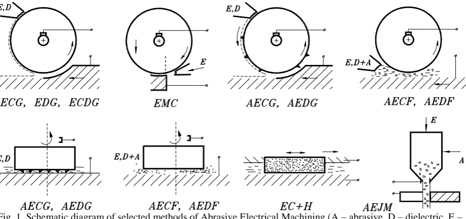
Depending on type of tool and working movements, that are used in particular process, there are many various methods, schematic diagrams of which are shown in Fig. 1. Among the others, there are: - methods making use of abrasive tool with metallic bond: Abrasive Electrochemical Grinding (AECG), Abrasive Discharge Grinding (AEDG), and Electrochemical Honing (ECH); – methods using free abrasive grains: Abrasive Electrochemical Finishing (AECF), Abrasive Electrical Discharge Finishing (AEDF), and Ultrasonic Electrochemical Machining (USECM)
Interconnections between machining mechanisms, which take part in metal removal process, cause the productivity of hybrid machining to be much greater than summed up results of the individual processes (assuming that the same parameters, characteristic for relevant processes, are kept). Similar positive effects have been achieved in respect to energy consumption and surface finish. In order to present the phenomena and factors that occur during given electro-mechanical machining processes, and which influence on these positive results, we will consider abrasive electro-chemical machining process, such as Abrasive Electrochemical Grinding (AECG) (Figs. 2.)
Electrochemical grinding with metal bonded abrasive tool (AECG), consists in combination mechanical and electrochemical processes, acting on the workpiece, what considerable changes performance indexes of the machining process. Process productivity are increased many times, surface layer properties are improved, while tool wear and energy consumption decrease. Particularly effective is AECG process for machining parts made from difficult to cut materials, such as sintered carbides, creep resisting alloys (eg. Inconel, Nimonic), titanium alloys, metallic composites (eg. PCD-Co, Al.-SiC, Al-Al2O3) [1]. Increase in performance indexes of hybrid machining proceses, such as AECG process, results from interconnections between microcutting, electrochemical dissolving, changes in surface layer properties of material in machining area, and processes that take place in active layer of the grinding wheel surface.
Schematic diagram of AECG process in the case of plane surface grinding with circumferential face of the wheel is shown in Fig. 2. The following zones can be distinguished within the machining area: EC zone, where anodic dissolving prevails, and G + EC zone, where microcutting predominates. The participation of either of these two mechanisms in material removal process, and in surface layer creation, changes as AECG process parameters are changed.
Analysis of Abrasive Electrochemical Grinding
Process (AECG)
Fig. 1. Schematic diagram of selected methods of Abrasive Electrical Machining (A – abrasive, D – dielectric, E – electrolyte) [3].
Fig. 2. Schematic diagram of abrasive electrochemical grinding (AECG)
For example, when we are changing feed rate Vf, while keeping the other parameters of the process constant, and Vf reaches value which is smaller than certain critical value Vg, then microcutting vanishes, because at these conditions the smallest gap S, between working surface of the electrode TE
(grinding wheel bond surface) and workpiece (WP) surface, is greater than height h of the protruding fragment of abrasive grains. Depth of allowance to be removed, that is the real depth of cut am, can be considerable greater than set value ae, and it depends on anodic dissolving. Action of the abrasive grains is limited to their influence on conditions existing in the gap, and in particular on electric field, transport of electrolyte, and hydrodynamic effect on near-anode boundary layers.
Increase in lengthwise-feed rate Vf results in gap size S. decrease, and, after value Vg has been exceeded, gap width s. along the definite length 1-2 (Fig. 2), become smaller than value h, and in consequence microcutting contribution to metal removal process increases. Further increase in feed rate Vf causes gap width under axis of the wheel to become also smaller than h. At this moment, depth of cut is approaching value ae, because beyond the grinding wheel anodic dissolving contribution to metal removal process is relatively small. However, it should be noted, that influence
of anodic dissolving on ground surface layer condition in area beyond the wheel may be significant.
For determination of basic characteristics of the process,
namely the output data considering between depth of microcutting ,g, the real depth of cut ,am, material removal rate MRR, as a function of chosen input data, such as setting depth of cut ,ae, feed rate ,Vf ,working voltage ,U, angular velocity ,, the mathematical modeling and computer simulation have been developed.
II.MATHEMATICAL MODELING OF THE AECG PROCESS During the first stage of AECG process modeling, it is essential to derive the distribution of interelectrode gap (S), which results from anodic dissolution. At this stage, the microcutting process is not taken into account for estimating material removal rate, however it is included in the electrochemical machinability coefficients (kv) and total overpotential (E). When the distribution of interelectrode gap (S) is derived, it is possible to determine the G + EC
zone with microcutting, as the zone where abrasive grains sticking out (height of grain – h in the Fig.1, h>Sn) of the bonding material of grinding wheel (Fig. 2 – hatched area between points 1 and 2) cross with the surface of machined material. In this way it is possible to derive dimensions of machining zones EC and G + EC, and the depth (g) of layer machined by microcutting, as well as ratio g/ar.
Deriving of interelectrode gap distribution (S) in case of AECG is similar to ECG (often described as electrochemical machining using rotating electrode – ECM-RE), however in this case the working electrode (ER) is metal surface (with R radius), which is the averaged contour of metal bonding of grinding wheel. In the literature [4,5, and others], shape of the anode surface was derived basing on the steady state conditions of ECM-RE. It led to determining gap distribution (S) basing on the solution of nonlinear differential equation of 1st order. The drawback of this method, resulting in relatively big mistakes and ambiguous solutions due to lack of a priori initial conditions.
[image:2.595.60.294.308.446.2]Moment of ending machining process is defined by machining time of position of the electrode tool.
Modeling was performer using following main assumptions:
linear distribution of electric potential along the gap size ,S,
electrical conductivity of electrolyte , in the gap is constant,
uniform distribution of abrasive grains on the surface of grinding wheel (-ratio of metallic uncovered by grains surface of grinding wheel vs active side cylindrical surface of grinding wheel is known),
the electrochemical reactions will be accounted for by introducing the total overpotential E = Ea - Ec, where Ea and Ec are the overpotential potential of anode and cathode, respectively,
Basing on the theory of electrochemical shaping, the evolution of machined surface shape F(x,y,z,t) = 0, is described by the equation [5]:
F
t
kvi F
0
(1)The coefficient of electrochemical machinability kv is equal to the volume of material dissolved per unit electrical charge – in general it is the function of, among others, current density.
Going forward to the coordinate system (x, z) – Fig. 2, change of machining surface geometry z = Z(x, t) during AECG process is described by:
Z t kvi Z x 1 2 (2)with initial condition z = Z0(x) describing surface before machining.
The current density iis depends on medium conductivity in the gap and on the voltage U according to Ohm’s law, which is extrapolated to the whole gap size.
According to the assumptions concerning potential distributions, current density may be described as:
S
E
U
i
(3) where: i – mean anode current density including thepresence of abrasive grains (which are insulators) by ratio
During AECG process, the gap is equal to:
S x x 0 2 Z z 0 2R (4)
where: x0 = x0(t), z0 = z0(t) – equations describing movement of grinding wheel central point (TE).
Presented above equations 2 – 4 describe the process of electrochemical shaping. The system of equations (2) - (4) has been solved numerically using the Finite Difference Method. The simulation software basing on the same mathematical model were described in Ref.[6].
Figure 2 shows the evolution of anode shape achieved during simulation of AECG process for various positions of
[image:3.595.312.538.91.217.2]grinding wheel (x0). While analyzing presented graphs, it may be noticed that shape of the anode surface settles up with time and process becomes stationary.
Fig. 3. Evolution of anodic dissolved surface geometry III. ANALYSIS OF COMPUTER SIMULATION RESULTS For the needs of AECG process analysis, simulations were performed for various machining parameters and various characteristics of kv(i), conductivity , - ratio and dimensions R i h. Below are presented selected results for S0 = 0, R = 50 mm, kv = 1 mm
3
[image:3.595.312.549.406.663.2]/Amin, = 0.016 A/Vmm, = 0.3 and for following investigated parameters U - E = 6, 9, 12 V; Vf = 60, 120, 240, 480 mm/min; h = 25, 50, 70 m.
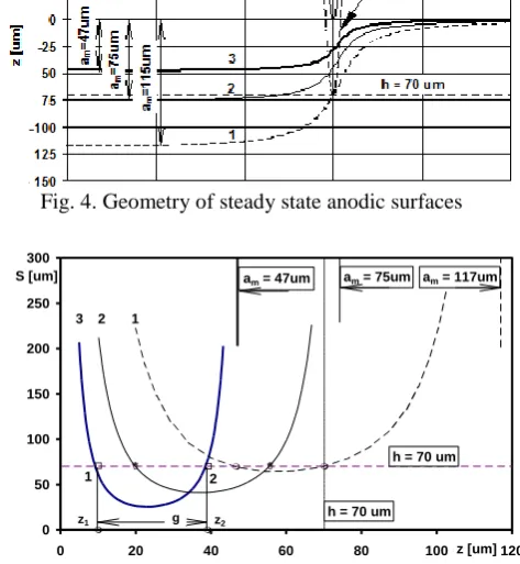
Fig. 4. Geometry of steady state anodic surfaces
Fig. 5. Distribution of the gap size along z axis Figures 4 and 5 show the steady state surfaces of the anode and distribution of gap (S) thickness for various machining parameters. There is also sketched the working electrode (ER) together with the abrasive grains sticking out of the wheel up to h = 70 m. Basing on the presented curves it may be stated that for parameters 1 and 2, the depth of grinding depends on the anodic dissolution (when U-E = 12 V and Vf = 60 mm/min) and real/achieved depth of machining am = 117 m is 1,64 times deeper than pre-set
0 20 40 60 80 100 120 140
0 5 10 15 20 25 30 35 40 45 50
x [mm]
z
[u
m
]
x0=25mm
x0=20mm
x0=15mm
x0=10mm
x0=5mm
x0=0mm
x0=-10mm
0 50 100 150 200 250 300
0 20 40 60 80 100z [um]120
S [um] am = 47um am = 75um am = 117um
h = 70 um
g
3 2 1
1 2 z2 z1
depth of ae = h =70m. Lowering interelectrode voltage to
[image:4.595.310.550.98.250.2]U-E = 9 V results in increase of microcutting process in material removal and depth of grinding drops to am = 75 m, the same reaching the level of pre-set ae. When the interelectrode voltage is set at U-E = 6 V, similar effect may be achieved by increasing linear speed Vf. For example, doubling the speed Vf (Vf =120 mm/min) caused lowering of maximal depth of dissolution to am = 47 m. In this case it may be stated that the depth of machining is mainly dependant on the pre-set depth ae = 70 m, and that during AECG process, the biggest share in material removal comes from microcutting process. The influence of electrochemical processes influences mainly mechanical properties of machined surface layer and reducing surface integrity.
Fig. 6. Interelectrode gap Sn(Vf) and depth of cut am(Vf) Important characteristics of the AECG process concern dependencies between gap width (Sn), maximal dissolution depth amand process parameters. These two factors, as well as, height of abrasive grains (h) influence the run of the AECG process. Dependencies of Sn(Vf) and am(Vf) for constant interelectrode voltage U-E = 6V, is shown in Fig. 6. In Fig 6 are also marked lines for two heights of abrasive grains: h = 50 i 70 m, what enables specifying ranges of Vf, for which different material removal processes are dominant. For example, for h = 50μm:
- when Vf, < 45,6 mm/min - dominant process is electrochemical dissolution (EC);
- 45,6 mm/min < Vf, < 111 mm/min - height of grain above bonding becomes bigger than Sn and the same microcutting appears (its share grows together with Vf);
- when Vf, > 111,4 mm/min – microcutting is dominant (marked as G + (EC) in Fig. 6) and depth of cut is almost equal to setting value ae ;
Above listed boundary values of Vf, depend on abrasive grain height (h) and interelectrode voltage (U). Basing on the results of simulations, regression equations for shares of processes have been derived:
- border between EC and G+EC:
189 [(U-E)/Vf ] 0.66 =h - border between G+EC and G+(EC):
[image:4.595.51.290.226.373.2]334 [(U-E)/Vf ] 0.65 = h Figure 7 presents limits for Vf and U-E when h = 25 i 50 m. Point P (marked on the graph) shows the conditions, when
[image:4.595.310.544.374.724.2]probability of sparking drastically increases (in case of voltage increase).
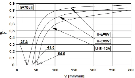
Fig 7. Relation between Vf and U-E for boundary conditions Basing on the real / experimental depth of grinding, it is possible to derive AECG process efficiency - qw in relation to grinding wheel width. It is expressed as qw = amVf. Achieved relationships between process efficiency and linear feed rate, for h = 70μm and various U-E, are presented in Fig. 8. Radical drops of characteristics result from changing conditions and process shares from G + EC
to dominant role of microcutting G + (EC).
Fig. 8. Efficiency of AECG as the function of linear feed rate.
Fig. 9. Ratio g/am as the function of linear feed rate Vf Important influence on the cutting forces, during grinding process, has the depth of layer which is microcut – g. In case of AECG process it is limited with the dimensions of G + EC i G + (EC) zones. Resulting from simulations values of ratio g/am are presented in Fig. 9. For the feed rates (Vf )
0 50 100 150 200 250
0 50 100 150 200 250 300 350 400
Vf [m/min]
am
,
Sn
[
u
m
]
h=50um h=70um
G+(EC)
EC
G+EC
Sn
am
[image:4.595.314.546.383.530.2] [image:4.595.310.548.557.695.2]slower than those equal to the limits of G + EC and
G + (EC), the share of g layer in grinding dept his significantly reduced. It leads to significant reduction of cutting forces, even to 0, when there appears pure electrochemical dissolution process.The boundary values of
Vf, at which microcutting disappears, and which are marked in Figure 9, depend on electrical parameters, electrochemical machinability of the material in a given electrolyte, and grinding wheel features, especially grain size and height h.
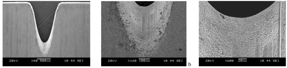
Dependencies achieved during simulation of the AECG process are similar to the results of machining. Experiments were conducted for machining slots of width equal to 0,3mm in 0,2mm thick stainless steel plate using brass bonded diamond grinding wheel (particle size 76μm with concentration of 30%). Electrolyte was 3% water solution of NaNO3. Tests were performed for constant interelectrode voltage of 6, 8 and 10 VDC with constant feed rate Vf = 1,2mm/min in each case. Results are presented in figures 10, 11 and 12 respectively.
Analyzing the presented SEM pictures of machined slots, there can be evaluated share of material removal processes.
In case of machining with interelectrode voltage U-E = 6VDC (Fig. 10), material was removed mainly by microcutting / grinding process – phase G+(EC) from Fig.6. There are visible traces of abrasive grains on the machine surface (bottom and side walls of the slot). When voltage was increased to 8VDC, also the share of electrochemical dissolution increased significantly (Fig. 11 and 12). In this case there is less traces of microcutting both in the bottom of the slot and its side walls – phase G+EC from Fig.7. After increasing voltage to 10VDC, the share of microcutting decreased and the dominant removal process was electrochemical dissolution – phase EC +(G) from Fig.7. High rate of electrochemical dissolution process is visible both on the geometry of the slot and on the surface at the bottom. However there are traces of abrasive grains on the machined surface, the grinding process has minor share in material removal.
a b
[image:5.595.52.545.301.419.2]c Fig. 10. Slots machined with AECG process with U-E = 6 VDC (a – magnification 40x, b – magn. 160x, c – magn. 600x)
a
[image:5.595.47.541.459.578.2]b c
Fig. 11. Slots machined with AECG process with U-E = 8 VDC (a – magnification 40x, b – magn. 160x, c – magn. 600x)
a
b c
[image:5.595.44.542.617.735.2]IV. CONCLUSION
Described simulation of AECG process allows to derive approximate characteristics of the material removal process including machining conditions. It is worth to notice that performed mathematical modeling, especially in the aspect of evaluating geometry of interelectrode area, bases on the assumptions idealizing the machining process. In this aspect, results of simulations shall be treated as approximation. Described model is good starting point for further development of the detailed model of AECG process, which would incorporate changes of the electrolyte properties in the interelectrode gap resulting from products of dissolution and microcutting.
REFERENCES
[1] Rajurkar K., P., ZhuD., Mc Geough J., A., Kozak J., DeSilva A., “New Developments in Electro-Chemical Machining”. Annals Annals of the CIRP, 1999 vol.48/2,p.569-579.
[2] Kozak J., Oczos K., “Selected Problems of Abrasive Hybrid Machining”, J. of Materials Processing Technology, vol. 109, No.3, 2001, pp. 360-366
[3] Kozak, J.: “Selected Problems of Hybrid Electro-Mechanical Machining”. Archives of Mechanical Technology and Automatization, 1996, Vol.16: 59-65 (in Polish).
[4] Noble C.F.: “Electro-Mechanical Action in PheripherialElectrochemical Grinding”, Ann. of the CIRP 32/1,1983
[5] Davydov .A., Kozak J.: High Rate of Electrochemical Shaping, Moscow: Nauka, 1990
[6] Kozak J., Rajurkar K.P., Ruszaj A., Sławiński R.J., “Sculptured Surface Finishing by NC-Electrochemical Machining with Ball-End Electrode (ECM-CNC)”,