Abstract- In the research an attempt has been made to explore
the feasibility of the application of electrochemical machining technique to make micro drill hole on Al/10vol%Al2O3-MMC.
An electrochemical micro machining (ECMM) setup has been developed and utilized for experimental investigation. The different experiments have been carried out to investigate the influence of the electrochemical machining process parameters on the material removal rate and radial overcut. Experimental results reveal that the machining voltage ranges from 5 to 10 volt gives higher material removal when HCl is added with NaCl electrolyte. The material removal rate increases with increase in machining voltage and concentration of NaCl electrolyte. From the micro photo and SEM graphs, it is clear that the application of NaCl as electrolyte gives better accuracy and surface quality as compared to NaCl + HCl electrolyte.
Index Terms- Electrochemical micro machining, MRR,
Overcut, Al/Al2O3-MMC, SEM photo graph.
I. INTRODUCTION
Advance engineering materials are gradually becoming very important material because of their superior properties, scope and applications in advance manufacturing industries. The metal matrix composite (MMC) is one of the important advanced materials has high wear resistance, fatigue strength, shock resistance, high strength to weight ratio etc. Because of these superior properties metal matrix composites have got wide industrial applications in the production of high performance cars, fiber glass tank and tubes, aircrafts, wind turbine blades, high temperature resistance components etc. However, machining of MMC is one of the major problems, which resist its widespread application [1]. Hence, it is essential for developing an efficient and accurate machining method for processing advanced composite materials. Electro chemical machining process is one of the best methods to machine the hard materials like carbide, composite etc. The traditional methods e.g. liquid stir casting technique applied to produce the components from MMC not fulfill the requirement of necessary tolerances and other closer dimensional accuracy features in practice. The production of micro dimensional through and blind holes, grooves, slots and odd shape contour, micro channel etc. on composite parts have also been difficult by traditional machining processes.
Manuscript Received Feb 02, 2016; Revised Feb 14, 2016
Alakesh Manna, Professor & Head, Department of Mechanical Engineering, PEC University of Technology (Formerly Punjab Engineering College), Chandigarh-160012, (India). Corresponding author:
M. + 91-9417565398; E-mail: [email protected]
Anup Malik, Research Scholar, Department of Mechanical Engineering, PEC University of Technology (Punjab Engineering College), Chandigarh. E-mail: [email protected]
Hence, it is essential to introduce the advanced machining processes to fulfill the above requirement. The electrochemical machining process is one of the most effective processes for effective machining of engineering composite
e.g. Al/10vol%Al2O3 MMC. The developed electrochemical
micro machining setup has been utilize to machine micro
holes on Al/10vol%Al2O3 MMC and subsequently analyzed
the machining performance characteristics with respect to the various parameters of this machining process.
II. LITERATURE REVIEW
Bilgi et al. [2] studied on the electrochemical deep hole drilling and concluded that the material removal rate varies with supply voltage and bare tip length. Hyun Ahn et al. [3] performed a study on electro-chemical micro drilling using ultra short pulses and concluded that localization distance can be controlled by controlling the voltage and pulse duration. Kazak et al. [4] investigated the micro-holes and grooves features during micro-electrochemical machining. Authors conclude that the side gap and the frontal gap decrease with increase in feed rate. Bhattacharya and Munda [5] studied on the ECDM during machining of non-conductive ceramic materials and conclude that the MRR is very low at low applied voltage, and over-cut on hole radius is greater at
higher electrolyte concentration. Sarkar et al [6] investigated
on the electrochemical discharge micro-drilling during machining of advanced ceramics. They concluded that the quality of the hole during micro-drilling greatly depends on the applied voltage and electrolyte concentration. Basak and
Ghosh [7] studied on the mechanism of material removal in
electrochemical discharge machining and concluded that the substantial increase in the material removal rate can be achieved by introducing an additional inductance in the
control circuit. Ming-Chang et al. [8] studied the effect of
carbon content and microstructure on the metal removal rate in electrochemical machining. They concluded that the material removal rate and current efficiency increase with carbon content and the roughness of the machined surface for annealed microstructure is greater than those of the quenched
and tempered steels. Singh et al. [9] studied on the
electrochemical spark machining (ECSM) process during machining of piezoelectric ceramic and concluded that material removal rate increased with increase in supply voltage and electrolyte concentration. Manna and
Bhattacharyya [10] studied on dual response approach for
parametric optimization of CNC wire cut EDM of particulate reinforced aluminium silicon carbide metal matrix composite. The significant factors were determined for each machining performance criteria from experimental results, through
Micro-Drilling of Al/Al
2
O
3
-MMC on
Developed ECMM
ANOVA and F-test values. Manna and Khas [11] investigated
on the micro machining of electrically non-conductive Al2O3
ceramic. Authors utilized the developed an electrochemical spark machining setup for experimental investigation and recommended some parametric ranges for higher MRR.
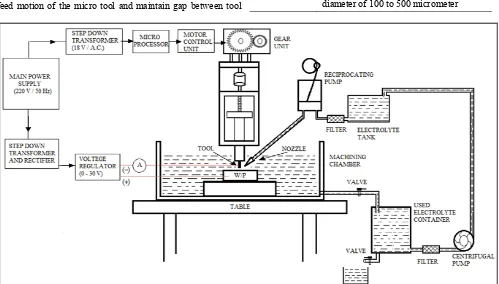
III. DEVELOPMENT OF ECMM SET-UP An electrochemical micro machining (ECMM) set-up has been designed and fabricated for micro-drilling of electrically
conductive Aluminum/Alumina (Al/Al2O3) MMC. Fig. 1
shows schematic diagram of ECMM set-up. The main supply A.C. 220 volt/50Hz stepped down to 18 volt/50Hz by a step down transformer. A rectifier is connected to the secondary winding of the transformer that converts A.C. to D.C. supply. This step down 18 volt supply used to run the stepper motor via microprocessor control circuit. The stepper motor is used to give the feed motion to the electrode. An automatic feed motion control circuit is used to give the feed motion to micro tool. An insulated tool holder was adopted to hold the electrode of 200 micrometer diameter. A job holder is designed and fabricated to hold the work-piece. Job holder is fixed inside the electrolyte chamber during experiment. A D.C. converter is used to convert the A.C. voltage into D.C. voltage and its output terminals are connected to anode and cathode. A potentiometer is used in the circuit to vary the supply voltage. Voltage from cathode of the D.C. generator was connected to the tool. Positive terminal of the regulator is connected to work piece (anode) and negative terminal is connected to micro tool (cathode). An assembly language base program is set to operate the tool movement via microprocessor and stepper motor unit. With the help of the stepper motor varies feed motion of the micro tool and maintain gap between tool
and work-piece about 0.5 mm. A submerge pump with filter (model HJ-311B, 220-240V/50Hz, 2W, capacity 300 l/h) is used for constant electrolyte flow.
IV. PLANNING FOR EXPERIMENTATION
An electrochemical micro machining setup was designed and fabricated for conducting the experimental investigation. Table-1 represents the details about the work-piece and electrolyte used for experimentation. The material removal rates are determined by difference of weight of work-pieces before and after each micro hole. Contech (Instrument) Electronic Balance of resolution 0.001 g was used to weight the work-pieces before and after each run. The radial overcut of micro holes were measured by utilizing shadowgraph (20X) of accuracy 1 micrometer. Different micro graphs of the micro holes were taken utilizing Scanning Electron Microscope (SEM) to analyze the surface texture of the machined hole.
Table 1 Details of experimental conditions
Machine tool Developed Electrochemical Micro
machining(ECMM) setup Electrolyte
Concentration
(A) Sodium Chloride (NaCl) with different concentration
(B) Sodium Chloride (NaCl) + Hydrochloric acid (HCl) with varying 50 : 10 to 125 : 25 + tap water
Work-piece Al/10%vol Al2O3-MMC; 2.5 mm thick.
Tool used IS-3748/ T35Cr5Mo1V30 with varying
[image:2.595.49.548.442.726.2]diameter of 100 to 500 micrometer
V. RESULTS AND DISCUSSION
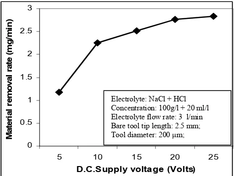
The effect of the process parameters e.g. D.C. supply voltage and electrolyte concentration on MRR and average radial overcut have been analyzed. Experiments were conducted with Nacl electrolyte and Nacl + HCl electrolyte. Fig. 2 (a) shows the variation of MRR (mg/min) with machining voltage. This result was acquired from a particular set of machining at 100 g/l NaCl electrolyte concentration, varied machining voltage, constant 50Hz frequency, 3.0 l/min electrolyte 0 0.5 1 1.5 2 2.5 3
5 10 15 20 25
D.C. Supply Voltage(Volts)
M at er ial r em oval r at e (m g/ m in)
Fig. 2 (a) variation of MRR with DC supply voltage 0 0.5 1 1.5 2 2.5
50 75 100 125 150
Electrolyte concentration (g/l)
M at er ial r em o val r at e (m g /m in )
Fig. 2(b) variation of MRR with electrolyte concentration
flow rate with 200 μm diameter steel tool and plotted the graph (Fig.2(a)). From Fig. 2(a), it is clear that MRR increases with increase in supply DC voltage. It is due to increase of current drawn side by side increase of supply voltage during machining. It obeys the basic theory of material dissolution from anode i.e. Faraday’s law. As the first law of Faraday’s states that “the amount of chemical charges ‘W’ produced i.e. dissolved is proportional to the amount of charge ‘Q’ passed through the electrolyte”. Which can be expressed as W α Q, if
Q = I . t, then, W α I, Where, I = machining current (Amp), t = time(s), W = material removed or dissolution (mg).
Fig. 2 (b) shows the variation of MRR with electrolyte concentration. From Fig. 2(b), it is clear that MRR increases with increase in electrolyte concentration. It may be due to the large number of ions associated during machining due to increase of electrolyte concentration and drawn more current in the machining process and thereby enhance material removal rate with increase in electrolyte concentration. Fig. 3(a) shows the effect of D.C. supply voltage on MRR. Experimental results obtained from a particular set of machining at parametric combination, i.e. NaCl + HCl electrolyte concentration (100 g/l + 20 ml/l), varied machining voltage at constant frequency 50Hz, 3.0 l/min electrolyte flow rate with 200 micrometer diameter steel tool are plotted to exhibit the influence of machining voltage on MRR. From Fig. 3(a), it is clear that initially there is a rapid increase in MRR with increase in D.C. supply voltage thereafter MRR increases moderately even with increase in supply voltage. It is due to increase of machining current by increase of machining voltage. Experimental results also proved that material removal rate increases with addition of HCl in NaCl electrolyte. It may be due to increase the activeness of the electrolyte and enhance large number of ions allied in the machining and ultimately increase the rate of dissolution of metal from anode.
0 0.5 1 1.5 2 2.5 3
5 10 15 20 25
D.C.Supply voltage (Volts)
M at er ia l remo val r at e (m g /m in )
Fig. 3(a) Variation of MRR with DC supply voltage
Fig. 3(b) shows the variation of material removal rate with electrolyte (NaCl + HCl) concentration. From Fig. 3(b), it is clear that initially there is a little increase in MRR with increase in concentration of NaCl + HCl together, thereafter MRR increases rapidly with increase in electrolyte concentration from NaCl + HCl : 75 +15 to NaCl + HCl : 100 + 20 (Table-1). It reveals that the rate of dissolution i.e. dissolution efficiency at electrolyte concentration range NaCl + HCl : 75 + 15 to NaCl + HCl : 100 + 20 is higher as compared to the other zone considered for the investigation and increases MRR.
Fig. 4 shows micro photos of the actual holes produced by developed electrochemical micro machining setup. Fig. 4 (a) shows the machined hole produced with NaCl electrolyte Electrolyte: NaCl
Electrolyte concentration: 100g/l Electrolyte flow rate: 3 l/min Bare tool tip length: 2.5 mm Tool diameter: 200 μm
Electrolyte: NaCl
Electrolyte flow rate: 3 l/min Supply voltage: 15 Volts D.C. Bare tool tip length: 2.5 mm Tool diameter: 200 μm
[image:3.595.307.543.388.565.2]
0 0.5 1 1.5 2 2.5 3 3.5
50+10 75+15 100+20 125+25 150+30
Ele ctrolyte conce ntration (g/l)
Ma
te
ri
a
l
re
m
oval
r
at
e
(m
g/
m
in
)
Fig. 3(b) Variation of MRR with electrolyte concentration,
Fig. 4 (a) Machined hole at 15 volts D.C. supply current, 100 g/l NaCl
concentration, 50Hz frequency and flow rate 3 l/min.
where as Fig. 4 (b) shows the machined hole produced with NaCl + HCl electrolyte concentration. From Figs. 4(a) and 4(b), it clear that generated machined hole shape and produced surface is better when machining operation was conducted with NaCl electrolyte as compared to NaCl + HCl electrolyte. The large overcut on hole radius was produced when machining with NaCl + HCl electrolyte. It is may be due to the following reasons such as (i) more activeness of electrolyte and as well as more number of ions associated in the machining, (ii) more number of spark generated during machining, (iii) rate of material removal is high, (iv) inadequate electrolyte flow rate, (v) acidic action of the electrolyte etc. It is also may be due to micro spark and heat
generation; and generation of gas bubbles like H2 gas during
machining.
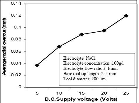
Fig. 5 (a) shows the variation of average radial overcut (ARO, mm) with DC supply voltage (Volts). This result is acquired at 100 g/l concentration, varied machining voltage at constant 50 Hz frequency and 3 l/min electrolyte flow rate with 200 micrometer diameter steel tools and plotted the graph
Fig. 4 (b) Machined hole at 15 volts D.C. supply current, (NaCl + HCl :
100g/l + 20ml/l) electrolyte concentration, 50 Hz frequency and 3 l/min
electrolyte flow rate.
0 0.02 0.04 0.06 0.08 0.1 0.12 0.14
5 10 15 20 25
D.C.Supply voltage (Volts)
A
ve
rag
e
rad
ial
o
ver
cu
t
(m
m
)
Fig. 5(a) Variation of radial overcut with DC supply voltage
to exhibit the influence of machining voltage on radial overcut. From Fig. 5(a), it is clear that the radial overcut increases with increase in supply DC voltage. It is due to increase of current drawn during machining as increase of machining voltage. Hence, current density increases and localization effect of current flux decrease as well as stay current flow rate increases that may be the caused of higher overcut with increase in machining voltage.
Fig. 5(b) shows the effect of D.C. supply voltage on average radial overcut (ARO). This graph is drawn from the acquired results at NaCl + HCl (100 g/l + 20 ml/l), 50Hz and 3.0 l/min electrolyte flow rate with 200 micrometer diameter steel tool. From Fig. 5(b), it is clear that initially there is a moderate increase in MRR with increase in machining voltage range from 5 to 15 Volt thereafter radial overcut increases rapidly with increase in supply voltage range from 15 Volt to 25 Volt. It is due to increase of machining current by increase of machining voltage. Experimental results also proved that material removal rate increases with addition of HCl in NaCl
Electrolyte: NaCl
Electrolyte concentration: 100g/l Electrolyte flow rate: 3 l/min Bare tool tip length: 2.5 mm Tool diameter: 200 μm Electrolyte: NaCl + HCl
[image:4.595.308.545.326.503.2]electrolyte. It may be due to increase the activeness of the electrolyte because of acidic in nature and enhance large number of ions allied in the machining.
0 0.05 0.1 0.15 0.2 0.25 0.3
5 10 15 20 25
D.C. Supply voltage (Volts)
A
ve
rag
e
rad
ial
o
ve
rcu
t
(m
m
)
[image:5.595.49.285.131.309.2]Fig. 5(b) Variation of radial overcut with Dc supply voltage
Fig. 6 SEM micrograph of a machined hole
Fig. 6 shows a Scanning Electron Micrograph (SEM) of
generated micro hole during micro drilling of Al/Al2O3-MMC.
The SEM graph shows the actual condition of the micro machined hole generated at 15 volt D.C supply voltage, 3 l/min electrolyte flow rate, 50 g/l + 10 ml/l (NaCl + HCl) electrolyte concentration with 2.5 mm bare tool tip length. This micro hole was machined utilizing 200 micrometer diameter steel tools for 35 minutes of continuous drilling. From the SEM graph, it is observed that micro drilling proceeds in the conical manner. The generated micro hole appeared very rough surface that may be due to the irregular sparking and sparks spread on the large area as well as irregular removal of molecules from the surface of the drilled hole.
VI. CONCLUSIONS
This investigation highlights the influence of various parameters of electrochemical machining on MRR and overcut.
It also highlights the suitability of the different electrolytes for
machining of Al/Al2O3 MMC. The MRR and radial overcut
both increased with increase in electrolyte concentration or with increase in D.C supply voltage or both. It is due to increase of current drawn during machining because of increasing machining voltage. The current density increased and localization effect of current flux decreased side by side stay current flow rate increased that may be the cause of higher overcut with increase in machining voltage. The radial overcut is high when HCl added with NaCl electrolyte for machining. At the initial stage of drilling the shape of the micro hole was circular with taper shape. Even after 5 min of continuous machining the shape of the micro hole still was circular in style. This observation is recorded during the micro
hole drilling at 5 volt DC supply voltage, 50 g/l electrolytic
concentration, 3 l/min electrolyte flow rate and 2.5 mm bare tool tip length. However, the present experimental investigation and research analysis on the machining of
Al/Al2O3-MMC on developed ECMM set-up will fulfill the
various requirements of machining and provide a new guideline to the researchers and manufacturing engineers.
REFERENCES
[1] A. Manna and B. Bhattacharyya. “A study on different tooling systems during machining of Al/SiC-MMC” Journal of Material Processing Technology, Vol. 123, 476-482, 2002
[2] Dayanand S.Bilgi, V.K Jain, R.Shekhar, Shaifali Mehrotra “Electrochemical deep hole drilling in super alloy for turbine application”, Journal of Material Processing Technology, Vol. 149, 445-452, 2004.
[3] Se Hyun Ahn, Shi Hyoung Ryu, Deok Ki Choi and Chong Nam Chu “Electro-chemical micro drilling using ultra short pulses” Precision Engineering, Vol 28, Issue-2, 129-134, 2004.
[4] Jerzy Kozak , Kamlakar P. Rajurkar , Yogesh Makkar “Selected problems of micro-electrochemical machining” Journal of Materials Processing Technology Vol. 149, 426–431, 2004.
[5] B. Bhattacharyya and J Munda “Experimental investigation into electrochemical micromachining (EMM) process” Journal of Materials Processing Technology, Vol 140, Issue 1-3, 287-291, 2003.
[6] B.R. Sarkar, B. Doloi, B. Bhattacharyya “Experimental investigation into electrochemical discharge microdrilling on advanced ceramics” International Journal of Manufacturing Technology and Management Vol.13, 214-225, 2008
[7] Indrajit Basak and Amitabha Ghosh “Mechanism of material removal in electrochemical discharge machining: a theoretical model and experimental verification” Journal of Materials Processing Technology, Vol 71, Issue 3, 350-359, 1997.
[8] Ming-Chang Jeng, Ji-Liang Doong and Chih-Wen Yang “The effects of carbon content and microstructure on the metal removal rate in electrochemical machining” Journal of Materials Processing Technology, Vol 38, Issue 3, 527-538, 1993.
[9] Y. P. Singh, Vijay K. Jain, Prashant Kumar and D. C. Agrawal “Machining piezoelectric (PZT) ceramics using an electrochemical spark machining (ECSM) process” Journal of Materials Processing Technology, Vol 58, Issue 1, 24-31, 1996.
[10] A. Manna and B. Bhattacharyya, “Taguchi and Gauss elimination method: A dual response approach for parametric optimization of CNC wire cut EDM of PRAlSiCMMC”, Int. J. Adv. Manuf. Technology, Vol. 28: 67-75, 2006.
[11] A. Manna and Kanwaljit Khas , “Micro machining of
electrically non-conductive Al2O3 ceramic”, Journal of
Machining and Forming Technologies, Vol. 1, Issue 1/2, 101-112, 2009.
AUTHORS BIOGRAPHY
First Author: Dr. Alakesh Manna
Professor & Head, Department of Mechanical Engineering, PEC University of Technology (Formerly Punjab Engineering College), Chandigarh-160012, (India). Phone No. +
91-9417565398; E-mail: [email protected]
He has 18 years industrial and 12 years teaching experience. He has published 207 research papers in international and national journals of repute and in the proceedings of the international and national conferences. His research areas include advanced and micro-manufacturing, fabrication of MMCs, hybrid and ceramics materials, traditional, non-traditional, advanced, hybrid and micro machining. He is also reviewer of many international and national journals of repute. He has guided 10 Ph.D. and 22 post graduate theses. He is guiding 6 PhD research scholars and 02 ME scholars at present. He has delivered about 150 expert lectures on different topics. He also chaired many technical sessions in the international and national conferences. He has organized many faculty development programme and national conferences. He wrote two text books ‘A Text Book of Reliability and Maintenance Engineering” and “A Text Book of Manufacturing Science and Technology-Part-I (handed over to publisher)”. He is principal investigator of different project and scheme. He is recipient of gold medals for best and excellent teaching thrice and various medals, memento, certificates for his excellent past service during Indian Railway. He has received best research paper awards two times from Institution of Engineers (India). He is a recipient of Prof. D. N. Trikha excellence in Research Publication Award-2010.
Second Author: Mr. Anup Malik, Ph.D. Research Scholar, Department of Mechanical Engineering, PEC University of Technology (Formerly Punjab Engineering
College), Chandigarh, (India). E-mail: