Volume 2, 2018, Pages 111–117
SUMO 2018- Simulating Autonomous and Intermodal Transport Systems
Road network extraction with OSMNx and SUMOPy
A. E. Dingil
1, J. Schweizer, F. Rupi
2, and Z. Stasiskiene
11 Institute of Environmental Engineering Engineering Faculty, Kaunas University of
Technology/Lithuania
2
Dept. of Civil, Environmental, Chemical and Materials Engineering (DICAM) - University of Bologna, [email protected]
Abstract
The microsimulation of larger cities would be of a considerable gain for urban planning. However, compared with traditional traffic flow assignment models, transport networks suitable for microsimulations require a large amount of data (connectivity, properties, road/rail signaling, etc.). One persistent problem with microsimulation models has been that the creation of large urban networks is very resource consuming. Therefore, it would be of considerable value if the modeling process of microsimulation networks could be largely automated.
SUMO is one of the most versatile, open source mobility simulators with the capability of modeling virtually all urban transport systems, including roads, rail and even water-ways. Openstreetmap (OSM) is an open and feature-rich editable map of the world that is potentially the best data-source for creating micro-simulation networks. But OSM data is incomplete, imprecise and imperfect as it is edited by volunteer laymen, and it has many descriptive, but ambiguous attributes that leave ample room for interpretation.
The present work proposes an alternative method to import OSM data into SUMO with the goal to generate a functioning SUMO microsimulation network that is as close as possible to reality, while overcoming some of the deficiencies buried in OSM data. For this purpose, a recent software package, called OSMNx is used, which generates a directed graph (as networkx graph object) from OSM data, by resolving many topological issues. Both, OSMnx and networkx are Python packages. Within the SUMOPy framework, the following additional software is developed: (i) a converter from networkx graph to a SUMO network; the conversion is performed by processing additional information from the original OSM data; (ii) a realistic traffic light system generator for major intersections.
It is shown that the software converts even complex junctions correctly into a SUMO network. However, the creation of efficient traffic light systems (a prerequisite for simulat-ing a larger urban area) turns out to be problematic as deficient information from OSM is difficult to replace by heuristic methods.
1
Introduction
• The network is incomplete; complete missing ways cannot been tracked, but often it is possible to complete the missing data by inference and consistency checks from other data (for example if a road is marked as one-way, but the power line for the trolley bus are marked as both-ways).
• The network is imprecise, in particular the connectivity of ways: if ways that are joined in reality do not have a common node in OSM; often intersections, with a complex cluster of inter-connected roads, footpaths, tramsways and bike-ways, are not correctly modeled; as a consequence the correct clustering of nodes is a challenging task.
• Ambiguity: the OSM definitions are ambiguous, in particular with the description of lane properties (access, speed, etc); newer OSM tags have been introduced to remove this ambiguity, but they require more efforts and are not in widespread use.
• Errors: there are errors within the way- and node attributes; some can be found by identifying contradictions, others are more difficult to identify (for example if a bikeway is declared as a lane but is is also modeled a separated way).
As a result of these imperfections, most microsimulation networks imported from OSM need to be corrected and completed manually, which has been repeatedly reported as time consuming activity [2].
One of the biggest challenges is the creation of a 3D-planar network from OSM information. The correct representation of OSM network topology may fail in 3D planar networks in a cities such as Tokyo, Los Angeles, Beijing with numerous grade-separated expressways, bridges, and tunnels. Network topology problems related to 3D-planar network analyses have been studied to create an Arcgis tool to overcome overlapping of passes, bridges, tunnels over highways that were previously counted as intersections [3].
Another problem with dense European medieval cities such as Bologna and Porto is that the the network conversion tends to underestimates the lengths of edges, and overestimates the number of nodes [1].
This paper describes a new method to overcome the aforementioned problems, by fully exploiting the features of a specialized OSM conversion software, called OSMnx.
2
OSMnx method to convert OSM data to a SUMO
net-work
The main idea is to exploit the OSMnx which is a python module in order to create a transport graph. OSMnx’s main features are:
• network extraction/cleanup/simplification and node clustering,
• OSM to JSON extraction and conversion,
• node elevation determination via Google API.
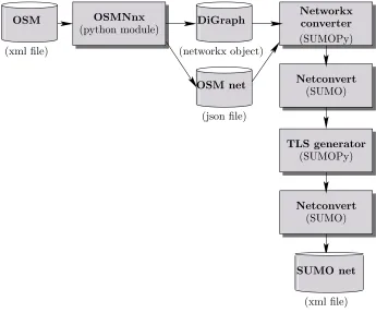
The complete method for importing OSM and for generating a correct SUMO network [4] involves a chain of external software packages and additional processes, which are illustrated in Fig.1. All steps are available as a unique script in the SUMOPy package as a part of the SUMO distribution [5].
OSMNnx (python module)
(SUMOPy) Networkx converter
Netconvert (SUMO)
TLS generator (SUMOPy)
Netconvert (SUMO) DiGraph
OSM net
(json file) (networkx object)
SUMO net
(xml file) OSM
(xml file)
Figure 1: Scheme of OSMNx-SUMO import process.
data into a directed networkx graph object. Networkx is a python module specialized on graph analysis. OSMnx produces also a JSON database where features of all relevant OSM objects are stored. Based on the networkx graph and the JSON database thenetworkx convertertranslates the networkx graph into a raw SUMO network. The raw SUMO network is then completed and connected with the standardSUMO netconvert tool. In a final step, traffic light systems are created for the major junctions.
2.1
Networkx converter
The OSMNx package converts OSM data to a networkx DiGraph object, and the Networkx converter generates a raw sumo net from the networkx DiGraph. This graph represents the transport network with edges, nodes and some attributes. OSMNx produces also a JSON file containingall OSM attributes of ways and nodes of the converted area. The nodes and edges of the DiGraph retained an OSM ID with which it is possible to associate an edge or node with their respective attribute in the JSON database. However, the edges of the DiGraph and their respective orientation still correspond to the ones in OSM. This means an additional interpretation process is needed to match the refined lane-by-lane structure which is required by the SUMO network. In particular the Networkx converter needs to perform the following tasks:
needed. For example if the OSM way attribute saysoneway = yes then only one edge is created, even though another attribute of the same way statescycleway=opposite; in this case the converter needs to create an edge with bicycle access to be created in the opposite direction.
• lane guessing: OSMNx does not create lanes with distinct properties; the converter needs to be guessed the number of lanes in both directions from the OSM edge attributes in the JSON database. OSM has 2 different lane-schemes: Either lanes are given explicitly, or they must be guessed from the attributes concerning bikeways, footpath, lanes in opposite direction etc.
• lane and edge attributes: SUMO needs to know specific attributes for edge and for each lane (for example access rights); again the converter guesses these attributes from the OSM database.
In practice, these tasks have been performed in the following steps:
1. A hierarchy of object classes have been developed, one class for each OSM highway type. The classes have methods to interpret highway-type specific OSM ways, such as the oneway/twoway estimation, the lane number estimation, the lane attribute guessing edge priority guessing, etc.
2. For each OSM way in the JSON data base, a way-object of the corresponding highway class is instantiated and the respective OSM attributes are interpreted.
3. footpaths-type ways are united with road or bikeways running in parallel; this turned out to be a good measure to simplify intersections
4. The edges of the DiGraph are read and combined with the interpretation of the respective way-objects; a raw SUMO graph with the correct edges, lanes, nodes and runarounds is created.
After the Lat/Lon coordinates have been translated into a (guessed) local coordinate system, a netconvert run has completed the connectors and estimated traffic light. However, traffic light systems for major intersection have been created in a separated step, as explained below.
2.2
Traffic light system generator for large/complex road junctions
The principle steps of the TLS generator for an entire network are as follows: In an initial step, all major routes of the network are identified. A “major route” is a sequence of successive edges which all satisfy the “major route criteria” (for example priority greater 7 or more than 2 lanes or speeds greater 90km/h). Then,“seed nodes” are determined, where major routes cross; seed nodes are the nodes around which the major traffic light system are constructed:
1. Node identification: identify the node cluster of this traffic light system, by building a set of all nodes that are reachable from the seed node. There is a forward and a backward tree search to identify all nodes within a predefined distance from the seed node.
2. For all nodes, the connectors with respective conflicting connectors are identified; a con-flicting connector is a connector that geometrically intersects another connector.
3. All routes that potentially cross the traffic-light system are generated; their route length is also determined;
4. For all crossing routes, the set of used connectors and the set of their respective conflicting connectors is identified.
5. For each crossing route, the conflicting connectors are used to create a phase (a phase where all conflicting connectors become red); if a conflicting connector is in a TLS-internal node, then all upstream connectors of the conflicting connector turn red, while the original conflicting connector remains unused (and will be removed later). This process is used for all routes, starting with the major routes; An preliminary phase duration is determined for each crossing route, which is at this stage simply the length of the route. (the final duration will be scaled during the last step); The simplistic assumption behind this idea is that the traffic volumes of a route are proportional to its length.
6. the phases of routes that use the same conflicting connectors (or compatible conflicting connectors) are merged; this set is to reduce the number of phases;
7. connectors which are always green and unused connectors of internal nodes are removed
8. Yellow phases of a predefined length are inserted in between each of the previously gen-erated phases. All red phases can be inserted on demand.
9. All preliminary phase durations are scaled to meet a predefined cycle time; in addition a minimum phase time can be defined in order to prevent too short phases.
This traffic light generation procedure is not optimum, but is needed to define the structure (connectors) of the TLS, and the basic signal phases which can be optimized in a successive step.
3
Network examples
(a) (b) (c)
Figure 2: Imported networks from (a) native SUMO-OSM import, (b) OSMNx import and (c) satellite image.
(a) (b)
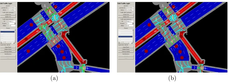
Figure 3: Generation of traffic light systems. TLS in two different phases.
between native OSM import and OSMnx import. It appears that the OSMnx import has a few less edges, node and connectors. Some edge in the native import are overlapping. There seems also a difference in interpreting OSM attributes: for example on some edges the native import shows a lane with general access and with segregated footpath whereas OSMnx import shows a footpath with segregated bike lane. It needs to be studied in more detail whether, such small differences have significant effects when simulating the network.
Comparing both, imported networks with the satellite image there are some dis-alignments of the pedestrian and cyclist network. In particular the footpath is often missing or too much in the imported networks. But the footpath is often not well modeled in the OSM data and in the absents of information, the interpretation remains difficult.
4
Conclusions
The present work has proposed an alternative method to import OSM data into SUMO with the goal to generate a functioning SUMO microsimulation network that is as close as possible to reality, while overcoming some of the deficiencies buried in OSM data. For this purpose, a recent software package, called OSMNx has been used, which generates a directed graph (as networkx graph object) from OSM data. Within the SUMOPy framework, additional software has been developed: (i) to convert the networkx graph into a SUMO network while processing additional information from the original OSM data given in JSON format; (ii) to create realistic traffic light systems at major intersections.
An example has been shown that the import method shows some improvements over the native SUMO-OSM import in terms of net-topology.
A big issue is the TLS generator at major junctions, as without a well calibrated TLS the circulation in bigger cities will brake down. Some heuristic methods have been proposed on how to solve such problem. However, the traffic light phases still need to be optimized in order be able to deal with realistic traffic scenarios. The validation of the network with observed traffic flows at bottleneck junctions is certainly one of the next steps to undertake.
References
[1] J. BOEING. Osmnx: New methods for acquiring, constructing, analyzing, and visualizing complex street networks. Computers, Environment and Urban Systems, 65:126–139, 2017.
[2] L. Codeca, R. Frank, S. Faye, and T. Engel. Luxembourg sumo traffic (lust) scenario: Traffic demand evaluation. IEEE Intelligent Transportation Systems Magazine, 9(2):52–63, Summer 2017. [3] A. KARDUNI and A. KARDUNI S. DERRIBLE. A protocol to convert spatial polyline data to network formats and applications to world urban road networks.Scientific Data, 3(160046), 2016. [4] Daniel Krajzewicz, Jakob Erdmann, Michael Behrisch, and Laura Bieker. Recent development and applications of SUMO - Simulation of Urban MObility. International Journal On Advances in Systems and Measurements, 5(3&4):128–138, December 2012.