Please cite this article as: T. Yuvaraja, K. Ramya, Implementation of Control Variables to Exploit Output Power for Switched Reluctance Generators in Single Pulse Mode Operation, International Journal of Engineering (IJE), TRANSACTIONS A: Basics Vol. 29, No. 4, (April 2016) 505-513
International Journal of Engineering
J o u r n a l H o m e p a g e : w w w . i j e . i rImplementation of Control Variables to Exploit Output Power for Switched
Reluctance Generators in Single Pulse Mode Operation
T. Yuvaraja, K. Ramya
Department of Electrical and Electronics Engineering, Sri Ram College of Engineering, Bangalore, India
P A P E R I N F O
Paper history:
Received 30 November 2015 Received in revised form 06 April 2016 Accepted 14 April 2016
Keywords:
Optimal Phase Current Shape Control Variables
Switched Reluctance Generator
A B S T R A C T
This paper presents an analytical modeling method of optimal control variables to maximize output power for switched reluctance generators (SRGs) in single pulse mode operation. This method extends the basic theory of the Stiebler model and utilizes the flux linkage function to express the inductance model of SRG. In this paper, the optimal phase current shape of SRG for maximum output power is investigated to determine optimal control variables based on phase current model. The expression of phase current in this paper that is in terms of control variables is solved using the basic equation of phase voltage based on inductance model, and then the characteristics of phase current and the energy conversion relations are analyzed to determine optimal shape of phase current. Furthermore, the expressions of phase flux linkage, rms phase current, and phase torque based on the proposed phase current model are presented in this paper to know the trend of main electrical losses. Results from analysis show that the switched reluctance generator with the optimal control variables can produce maximum output power and the shape of phase current in this case is flat top. Simulation and experimental results are presented to verify the proposed method.
doi: 10.5829/idosi.ije.2016.29.04a.09
1. INTRODUCTION1
Switched reluctance generator (SRG) is the potential candidate in various applications, such as automotive starter/generator [1, 2], engine starter/generator [3, 4] and variable speed wind energy [5] because of its simple structure, low cost, fault tolerant with a rugged structure, easy starting/generating realization, high speed adaptability, and high generation efficiency.
Highly nonlinear nature is main problem of the SRG, therefore the behavior of the SRG cannot be described by mathematical equation using conventional methods for a suitable controller design [6]. The SRG model is used to simulate to find the relationship between output power and control variables since there is no analytical equation for finding the output power based on design parameters and control variables [7]. The dynamic model of SRG using cubic spline technique has been proposed to find the flux linkage, inductance, torque, and output power [8]. The model SRG based on FEM
1 *Corresponding Author’s Email: [email protected] (T. Yuvaraja)
and power control methods for the small wind power generation system have been proposed in the literature [9]. The SRG model is used to find the output power curve versus shaft speed. This curve is analyzed to determine the optimal switching on-off angle for maximum efficiency of system.
linkages, one is the position which stator and rotor pole corners begin overlap and the other one is the position at maximum value. A modified angle position control (MAPC) method has been proposed to determine the optimal shape of the phase current [13]. The optimal turn-on angle is fixed and the optimal turn-off angle can be determined by the analytical model of SRG for the maximum energy conversion [14, 15].
In mathematical model for analyzing control variables and describing behavior of SRG, the flux linkage versus current characteristics calculation is the essential knowledge. At least, there are two methods to obtain flux linkage versus current characteristics; simulation approach based on Finite Element Method (FEM) and experimental approach based on direct measurement. The flux linkage model based on FEM is well known for its reliability, however it requires intensive computation and many details of the machine geometry and structure [16]. The analytical nonlinear models of flux linkage have been described in some works [17-20] that are accurate and reliable. The model based on machine geometry introduced in the literature [17] is complicated that depends on flux linkage at aligned and unaligned positions, and a position dependent function. The position dependent term has a physical significance that its coefficient needs to be related to the machine geometry. The model proposed by Roux and Morcos [18] is little complex because the flux linkage curve is divided into 2 parts, linear and nonlinear parts. However, it only requires the flux linkage versus current characteristics at the aligned and unaligned positions. The model described by Chi et al. [19] based on Fourier series with limited number of terms is complex since it is necessary to know the flux linkage versus current characteristics at the aligned, unaligned, and midway positions. The coefficients in terms of Fourier series depend on the flux linkage positions at aligned, unaligned, and midway that the flux linkage at aligned and midway positions can be calculated via curve fitting based on an arc-tangent function. The Stiebler model proposed in the literature [20] is simple that is composed of an angular function, aligned and unaligned flux linkage. However, it is proposed in per-unit system.
In this paper, an analytical modeling method of optimal control variables to maximize output power for SRG in single pulse mode is presented. This method extends the basic theory of the Stiebler model and utilizes the flux linkage function to express the inductance model in real system. The expression of phase current in terms of control variables proposed in this paper is solved from the basic equation of phase voltage based on inductance model. The control variables comprise a DC bus voltage, a shaft speed or angular velocity, and excitation angles. The optimal shape of phase current is analyzed to determine the optimal control variables based on the phase current
model. Furthermore, the equations of the flux linkage, rms phase current, and torque based on the current model are proposed to know the trend of the main electric losses. The 8/6 SRG experimental setup is used to verify the proposed method
2. PRINCIPLE OF SRG IN SINGLE PULSE MODE
OPERATION
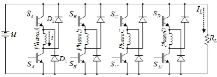
A 4-phase 8/6 SRG is used in this paper which is driven by a 4-phase asymmetrical bridge converter as shown in Figure 1. When SAand SA’ are both on, the phase A voltage is U. When SAand SA’ are both off, the phase A voltage is U.
The mutual inductance between individual phases of the SRG is usually neglected. Therefore, the equation of voltage for each phase of SRG is expressed as the voltage equation at constant speed which is given by:
dt i d Ri
U (,) (1)
The voltage equation at constant speed is given by:
e
dt
di
L
Ri
U
(
)
(2)where u represents the DC bus voltage, i is the phase current, R and L are the phase of resistance and inductance, respectively, ɷ is the angular velocity, and the back emf is defined as:
i
L
(
i
,
)
e
(3)The energy converted is the area enclosed by the loci which is expressed as:
di
id
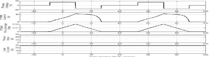
(4)The SRG requires an excitation source in order to generate electrical energy. The SRG (phase A) is excited by the asymmetrical bridge converter as shown in Figure 2. This of the SRG through two switches as shown in Figure 2 (bottom) and demagnetizing the same phase through two diodes as shown in Figure 2 (top). In Figure 2, the current builds in the SRG phase winding when the controllable switches are closed. In this duration, no energy is supplied to the load. When the controllable switches are opened, the store field energy is supplied to the load through the two diodes.
Figure 2. Power generation process for the SRG in single pulse mode
The average load current can be defined as:
e
o ff o ff
o n
id id N I
r L
2 1
(5)
where turn- θon and turn- θoff angles represent the controllable switches which are closed and opened, respectively, θe is angle at which phase current is depleted and it is given as 2 θoff - θon, θ is the rotor position and Nr is the number of rotor poles. The average electric power of the SRG is the summation of output power of each phase in one revolution which is given by:
PL = IL*U (6)
The main electrical losses of a SRG are copper loss and iron loss. The copper loss Pcudepends on the rms phase current Irms in the range θoff ≤ θ ≤ θe [21] which is expressed as:
R I N
Pcu ph rms2
(7)
e
off d i N I
r rms
2
2
2 1
(8)
The iron loss is proportion to the excitation magnetic motive force and the stroke frequency. It is not uniformly distributed in the core since flux shape is non-sinusoidal and a flux harmonic spectrum differs in various parts of the magnetic. The iron loss [22] can be approximately calculated as:
2 2
m e bB a m h
c K fB K f B
P m (9)
where F is the stroke frequency, Kn and Ke are the hysteresis and eddy-current loss coefficients, respectively, a and b are the constant of exponent, and
Bm is the amplitude of flux density for sinusoidal variation. The control variables of the SRG are the DC bus voltage u , the angular velocity
ω
, the phase current i , andturn on/off angle θon/ θoff. The Angle Position Control (APC) method can control the phase current shape by adjusting the θon and θoff while u and
ω
are constant. The output power can be adjusted by the phase current. The advantages of the APC method [13] can be described as follows: the optimal θon and θoff can improve efficiency, the multiple phases can be conducted at the same time, and the torque adjustment range is wide.3. PHASE CURRENT SCHEME
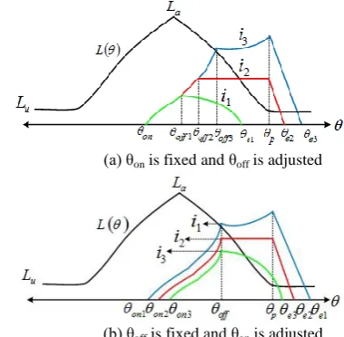
The effect of θon and θoff on the phase current shape using the APC method is illustrated in Figure 3. The θon is fixed and θoff is adjusted as shown in Figure 3(a). The θoff is fixed and θon is adjusted as shown in Figure 3(b). The resistance of the phase windings, the voltage drop of the main switches and diodes are neglected, the voltage in Equation (2) can be expressed as:
( ) i L(i, )
d di L
U (10)
The maximum value of the phase current in Figure 4 is in the range θoff ≤ θ ≤ θp.The θp equals to ( (βr + βs) /2) where βr is rotor pole arc and βs is stator pole arc. Consider that in Equation (10), if the back emf is
smaller than the DC bus voltage, then
d
di < 0. Phase
current shape in this case is shown in Figure 4 (a). If the
back emf is equal to the DC bus voltage, then
d di = 0.
In this case, phase current shape is shown in Figure 4(b). If the back emf is bigger than the DC bus voltage, then
d
di > 0 and phase current shape is shown in Figure
4(c).
(a) θon is fixed and θoff is adjusted
(b) θoff is fixed and θon is adjusted
From Equation (9), the iron loss depends on the maximum of flux linkage. The maximum value of flux linkage in Figure 4 can be known that occurs on the θoff. The copper loss depends on rms phase current that can be known by calculating in Equation (7).
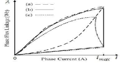
The energy conversion loops for 3 kinds of i and λ by the loci are shown in Figure 5. The maximum output power can be produced when the phase current is controlled in shape of the flat top (Figure 4(b)). This result has been confirmed the validity by Yu et al. [23].
(a) Back emf is smaller than DC bus voltage
(b) Back emf is equal to DC bus voltage
(c) Back emf is bigger than DC bus voltage
Figure 4. 3 kinds of phase current and flux linkage at different turn-on and turn-off angles with the same maximum value of the phase current
Figure 5. Energy conversion loops by the loci with the same maximum value of the phase current
Figure 6. Magnetization curve of a SRG
4. ANALYSIS OF OPTIMAL CONTROL VARIABLES
The optimal shape of the phase current in single pulse mode operation for maximum output power is the key to determine the optimal control variables. From Equation (10), the phase inductance model is a significant factor to find the phase current equation. The flux linkage function in per unit system proposed by Stiebler is developed as the inductance model in real system. The proposed model of the inductance in this paper is the real system which requires the geometrical parameters of a SRG at aligned and unaligned rotor positions. These parameters are easy to know using the experiment or the FEM. The parameters are inductance at positions of aligned La and unaligned Lu , and flux linkage at points s and m as shown in Figure 6.
In Figure 6, the flux linkage function at aligned rotor position is given as Equation (11) that is developed from the Stiebler model. This flux linkage is composed of linear and saturated regions. The saturated region begins at point s and finishes at point m. The flux linkage of the saturated region can be known by a
Froelich function λ =
bi a
i
where a and b are constant as a slop and intercept [24]. The constants of a and b
can be determined by substituting the λus, isof the point
s λam im of the point m into a Froelich function.
)
(
)
(
)
,
(
f
bi
a
i
L
L
i
L
i
u a u
(11)where k is the effective overlap position of stator and rotor poles, and the angular function can be given as:
k k k
f
,
0 cos 5 . 0 5 . 0 )
( (12)
To verify the proposed method, an 8/6 SRG is used to analyze to find its geometrical parameters using FEM that its specifications are shown in Table 1.
0º, 15º,30º obtained from the analytical model (11) compared with the FEM which demonstrates the validity of the proposed model.
TABLE 1. Specifications of the candidate SRG
Parameter Value
Outer diameter of stator 145 mm
Inner diameter of stator 63 mm
Stack length 63 mm
Number of phases 4
Pole Arc 24 degree
Number of stator/Rotor poles 6/4
Voltage 46 V
Power 2.2 kW
Speed 5500 rpm
TABLE 2. The analysis results obtained by FEM
Figure 7. Magnetization curve of the candidate SRG at rotor position 0º, 15º, 30º obtained by the analytical model and FEM
) ( )
,
( f
L bi a L L L L i L u u a u u (13) ) ( ) ( ) ( ) ( f bi a L L L u f bi a L L L u i u a u e u a u on (14)
Based on Equations (13) and (14), the phase flux linkage can be known by:
) , ( ) , (
i Li (15)
The phase inductance is much more, comparing with the mutual inductance, therefore the mutual inductance is neglected [25, 26]. The phase inductance model is proposed in this paper which is divided into three regions based on Equation (11) depending on phase current and rotor position which can be expressed in Figure 8.
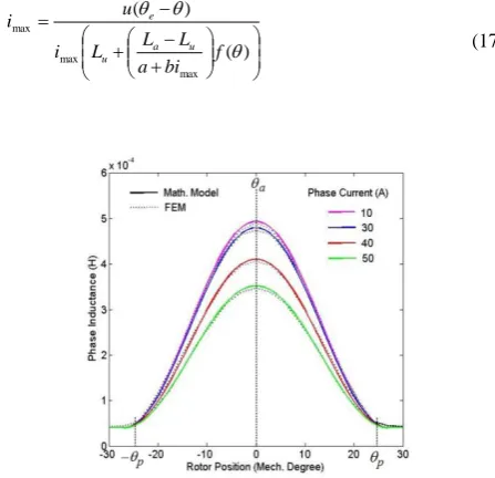
Figure 8 depicts phase inductance of the candidate SRG obtained by the proposed analytical model (Equation (13)) and FEM that the characteristics of the phase inductance versus current and rotor position closely match each other. The phase current model can be known by solving Equation (10) based on Equation (13) which can be expressed as:
2 ' 2 ) )( 2 ( ) ( ) )( ( ) ( ) ( ) ( ) , ( 2 1 ) , ( bi a b bL c b u i f L L bf f bi a L L i L i i T u u a u a (16)
In Figure 4, the maximum value of the phase current occurs on θ which is in range
off
e. So, the maximum value of the phase current can be given as:(17) ) ( ) ( max max max f bi a L L L i u i u a u e
Then, the maximum angular speed is given by: ) ( ) ( max max max f bi a L L L i u u a u e (18)
In order to obtain the optimal control variables, the phase current shape in Figure 4(b) is used to analyze. The phase current shape in this case is a flat top that the maximum value exists in the interval θoff to θp. If θ = θoff, the maximum value of phase current based on Equation (14) is:
k off u a u on off bi a L L L u i cos 2 1 2 1 ) ( 1 max 1 max (19)
If θ = θp, the maximum value of phase current based on Equation (14) is:
k p u a u p on off bi a L L L u i cos 2 1 2 1 ) 2 ( 2 max 2 max (20)
Since imax1 is equal to imax2 , the optimal turn-on angle can be calculated by substituting imax1 into imax.
max bi a
L L
q a u
(21) (22) k off f ) 0.6 0.6cos ( 1 k p f ) 0.61 0.6cos (
2
sin
a bimax
u z L L k k u
a
(23)
max 1 2sin a bi
L L u u a k k off
Figure 9. Schematic layout of the experimental setup
Figure 10. Experimental setup
5. SIMULATION AND EXPERIMENTAL RESULTS
To verify the proposed method, the 8/6 SRG system is used. A 3-phase induction motor is used as the prime mover that its speed is controlled by an inverter. Parameters of the SRG are shown in Table 1. A battery rated 12V 120A amount 4 pieces is used as the constant DC bus voltage u. The results indicate that the actual output power can be good for tracking variations in the command power, and that the dwell angle will be stabilized eventually. The control system is shown to have good dynamic performance. The average torque Tm of the prime mover is measured by a rotational torque transducer which is connected between the prime mover and the SRG. Shaft speed or angular velocity
ω
and aligned position are detected by a resolver mounted on the SRG. The SRG is driven by a 4-phase asymmetrical bridge converter that excitation angles are created by a TMS320F28027.Load resistance, equal to 1.25Ω, is used as the resistive load. Figure 9 shows the schematic layout of the experimental setup that the mechanical input power can be calculated by:
m
in T
P (24)
The efficiency of the system is defined as:
in out P P (25)
where output power is the electrical output power and input power is the mechanical input power.
In this paper, parameters used to analyze comprise Lu = 44 µH, La = 480 µH, βs = 25º, βr = 24º, a = 0.70, b = 0.186.
In the control scheme, the strategy consists of optimizing off q , and adjusting on q when the SRG is operated at a high speed. Figure 11 gives the relationship between the efficiency and off q. In the simulation, the source voltage is 150V, and the speed is 3000 rpm. Taking the selection range of on q in the practical application consideration, off q is selected at 46°. Figure 12 gives the experimental results of the relationship between the efficiency and the current shape. In the experiment, the source voltage is 150V, and off q and end q are fixed at 42° and 53.3°, respectively. From Figure 14, it can be easily seen that, the system efficiency is at its maximum when off end i =
Figure 11. Case 1: the θon and θoff are -9.2 and 9
Figure 12. Case 2: the θon and θoff are -7.8 and 9
Figure 13. Case 3: the θon and θoff are -8.15 and 9
Figure 14. Case 1: the θonand θoff are -9.2 and 9
Figure 15. Case 2: the θon and θoff are -7.8 and 9
6. CONCLUSION
In this paper, an analytical modeling method of optimal control variables to maximize output power for SRG in single pulse mode is proposed. This method extends the basic theory of the Stiebler model and utilizes the flux linkage function to express the inductance model in real system using a Froelich function. The expression of phase current in terms of control variables is proposed in this paper that is solved using the basic equation of phase voltage based on inductance model. The 3 kinds of phase current shape in single pulse mode are investigated that the optimal shape of phase current is flat top. The optimal phase current shape is used to determine the optimal control variables. In this paper, the optimal control variables can be known by calculation from the proposed analytical model in Equations (21)-(23). Furthermore, the equations of the flux linkage, rms phase current, and torque based on the phase current model are proposed to know the trend of the main electric losses. The results indicate that the flat-top current shape corresponds to the maximum efficiency when the output power is the same. The proposed control scheme has a good dynamic response, can be used over a wide speed range and is easy to accomplish. The 8/6 SRG experimental setup is used to verify the proposed method. Based on the experimental results, the SRG can generate the maximum output power and the phase current shape is flat top all cases when the SRG is controlled with the optimal control variables. The output power obtained from the measurement and analytical model is different with an average of 3.49%. This result demonstrates the accuracy and reliability of the proposed method.
7. REFERENCES
1. Fahimi, B., Emadi, A. and Sepe Jr, R. B., "A switched reluctance machine-based starter/alternator for more electric cars", Energy Conversion, IEEE Transactions on, Vol. 19, No. 1, (2004), 116-124.
2. Schofield, N. and Long, S., "Generator operation of a switched reluctance starter/generator at extended speeds", Vehicular
Technology, IEEE Transactions on, Vol. 58, No. 1, (2009),
48-56.
3. MacMinn, S. R. and Jones, W. D., "A very high speed switched-reluctance starter-generator for aircraft engine applications", in Aerospace and Electronics Conference, Proceedings of the IEEE 1989 National, IEEE, (1989), 1758-1764.
4. Ferreira, A., Jones, S. R., Heglund, W. S. and Jones, W. D.,"Detailed design of a 30-kw switched reluctance starter/generators system for a gas turbine engine application",
IEEE Trans. Industry Applications, Vol. 31, No. 3, (1995),
553-561.
5. Cardenas, R., Ray, W. and Asher, G., "Switched reluctance generators for wind energy applications", in Power Electronics Specialists Conference, 26th Annual IEEE, Vol. 1, (1995), 559-564.
6. Ziapour, M., Afjei, E. and Yousefi, M., "Optimum commutation angles for voltage regulation of a high speed switched reluctance generator ,"in Power Electronics, Drive Systems and Technologies Conference (PEDSTC), 2013 4th, IEEE, (2013), 271-276.
7. Asadi, P., Ehsani, M. and Fahimi, B., "Design and control characterization of switched reluctance generator for maximum output power", in Applied Power Electronics Conference and Exposition, Twenty-First Annual IEEE, (2006), 325-332. 8. Kerdtuad, P. and Kittiratsatcha, S., "Modeling of a switched
reluctance generator using cubic spline coefficients on the phase flux linkage, inductance and torque equations",
Advances in Electrical and Computer Engineering, Vol. 15,
No. 1, (2015), 41-48.
9. Choi, D.-W., Byun, S.-I. and Cho, Y.-H., "A study on the maximum power control method of switched reluctance generator for wind turbine", Magnetics, IEEE Transactions on, Vol. 50, No. 1, (2014), 1-4.
10. Chen, H. and Shao, Z., "Turn-on angle control for switched reluctance wind power generator system", in Industrial Electronics Society, 30th Annual Conference of IEEE, Vol. 3, (2004), 2367-2370.
11. Yilmaz, S. and Torrey, D. A., "Closed loop control of excitation parameters for high speed switchedreluctance generators", IEEE Trans. Power Electronics, Vol. 19, No. 2, (2004), 335-362.
12. Kioskeridis, I. and Mademlis, C., "Optimal efficiency control of switched reluctance generators", Power Electronics, IEEE
Transactions on, Vol. 21, No. 4, (2006), 1062-1072.
13. Yu, S., Zhang, F., Lee, D.-H. and Ahn, J.-W., "High efficiency operation of a switched reluctance generator over a wide speed range", Journal of Power Electronics, Vol. 15, No. 1, (2015), 123-130.
14. Wongguokoon, S. and Kittiratsatcha, S., "Analysis of a switched-reluctance generator for maximum energy conversion ,"in Sustainable Energy Technologies, IEEE International Conference on, (2008), 125-129.
15. Thongprasri, P. and Kittiratsatcha, S., "Optimal excitation angles of a switched reluctance generator for maximum output power", Journal of Electrical Engineering & Technology, Vol. 9, No. 5, (2014), 1527-1536.
16. Srinivas, K. and Arumugam, R., "Dynamic characterization of switched reluctance motor by computer-aided design and electromagnetic transient simulation", Magnetics, IEEE
Transactions on, Vol. 39, No. 3, (2003), 1806-1812.
17. Hossain, S. A. and Husain, I., "A geometry based simplified analytical model of switched reluctance machines for real-time controller implementation", Power Electronics, IEEE
Transactionson, Vol. 18, No. 6, (2003), 1384-1389.
18. Roux, C. and Morcos, M. M., "On the use of a simplified model for switched reluctance motors", Energy Conversion,
IEEE Transactions on, Vol. 17, No. 3, (2002), 400-405.
19. Chi, H.-P., Lin, R.-L. and Chen, J.-F" ,.Simplified flux-linkage model for switched-reluctance motors", in Electric Power Applications, IEE Proceedings-, IET. Vol. 152, (2005), 577-583.
20. Stiebler, M. and Liu, K., "An analytical model of switched reluctance machines", Energy Conversion, IEEE
21. Materu, P. N. and Krishnan, R., "Estimation of switched reluctance motor losses", Industry Applications, IEEE
Transactions on, Vol. 28, No. 3, (1992), 668-679.
22. Rafajdus, P., Hrabovcova, V. and Hudak, P., "Investigation of losses and efficiency in switched reluctance motor", in Power Electronics and Motion Control Conference, IEEE, (2006), 296-301.
23. Yu, S., Lee, D.-H. and Ahn, J.-W., "Efficiency analysis of switched reluctance generator according to current shape under rated speed", in Journal of International Conference on Electrical Machines and Systems. Vol. 2, (2013), 491-497.
24. Lin, R.-L., Chen, J. and Chi ,H.-P., "Spice-based flux-linkage model for switched reluctance motors", in Electric Power Applications, IEE Proceedings-, IET. Vol. 152, (2005), 1468-1476.
25. Krishnamurthy, M., Fahimi, B. and Edrington, C. S., "On the measurement of mutual inductance for a switched reluctance machine", in Power Electronics Specialists Conference, IEEE, (2006), 1-7.
26. Bae, H.-K. and Krishnan, R., "A novel approach to control of switched reluctance motors considering mutual inductance", in Industrial Electronics Society, Annual Conference of the IEEE, Vol. 1, (2000), 369-374.
Implementation of Control Variables to Exploit Output Power for Switched
Reluctance Generators in Single Pulse Mode Operation
T. Yuvaraja, K. Ramya
Department of Electrical and Electronics Engineering, Sri Ram College of Engineering, Bangalore, India
P A P E R I N F O
Paper history:
Received 30 November 2015 Received in revised form 06 April 2016 Accepted 14 April 2016
Keywords:
Optimal Phase Current Shape Control Variables
Switched Reluctance Generator
هديكچ
رًتاروش رد یجيرخ تردق ندواظر رثکادح ٍت یارت ٍىیُت لرتىک یاَریغتم زا یلیلحت یزاعلدم غير کی ٍلاقم هیا رد طاىغم تمياقم
یعی
تظا ٌدش ٍئارا طلاپ کت راک تلاح رد .
ا هی رظو غير ٍی ظاظا ی لدم رلثیتظا گ ٌرُت ي یری ارت راش عتات زا ی ت نای طواتکيدوا لدم SRG
ار
یم ٍعظًت .دَد جیار لکش ٍىیُت زاف ،ٍلاقم هیا رد SRG
لدم ضاظا رت ي ٍىیُت لرتىک یاَریغتم هییعت یارت یجيرخ تردق رثکادح یارت
تظا ٌدش یظررت زاف یلعف .
ٍلاقم هیا رد زاف نایرج یاَ ریغتم ةعحرت لدم ضاظا رت ي زاف شاتلي یمًمع ٍلداعم زا ٌدافتظا ات لرتىک
طواتکيدوا ٌدش لح یگصیي طپظ ي بًلطم لکش هییعت یارت یشروا لیدثت طتاير ي تلاح یاَ
درًم زاف یاُوایرج رارق لیلحت ي ٍیسجت
نایرج ،یدوًیپ زاف راش تراثع ،هیا رت ٌيلاع .دىتفرگ rms
لدم ضاظا رت زاف رياتشگ ي ،زاف زاف یاُوایرج
تخاىش ٍت ات تظا ٌدش ٍئارا
یت یکیرتکلا فلاتا یلصا دوير لصاح جیاتو .دماجوا
رًتاروش ٍک دَد یم ناشو لیلحت ي ٍیسجت زا طاىغم تمياقم
لرتىک یاَریغتم ات یعی
یم ٌدش ٍىیُت لکش ي یجيرخ تردق رثکادح دواًت زاف یاُوایرج
.تظا حطعم لاات درًم هیا رد تلاح هیا رد نایرج ي ٌدرک دیلًت ثش
ٍی
زاظ ی اتو ي جی یلمع رًظىم ٍت دیئات پ غير یداُىشی ٌدش ٍئارا .دوا